Investigation of splashing phenomena during the impact of molten sub-micron gold droplets on solid surfaces
Daozhi
Shen
a,
Guisheng
Zou
a,
Lei
Liu
*a,
Walter W.
Duley
b and
Y.
Norman Zhou
ac
aDepartment of Mechanical Engineering, The State Key Laboratory of Tribology, Tsinghua University, Beijing, 100084, China. E-mail: liulei@tsinghua.edu.cn
bDepartment of Physics and Astronomy, University of Waterloo, Waterloo, Ontario N2L 3G1, Canada
cDepartment of Mechanical & Mechatronics Engineering, University of Waterloo, Waterloo, N2L 3G1, Canada
First published on 29th September 2015
Abstract
The dynamics of splashing accompanying the impact of molten 800 nm diameter gold droplets on silicon, gold coated silicon, gold coated glass and polished solid gold surfaces has been studied. A novel method based on laser induced forward transfer has been developed to generate single submicron molten gold droplets. Splashing morphology has been characterized using Scanning Electron Microscopy (SEM) and Focused Ion Beam (FIB) techniques. It is found that the splashing of submicron gold droplets upon impact is enhanced by high droplet impact energy achieved by reducing the droplet flight distance and that an air layer resulting in a bubble becomes trapped under the impacting droplets even when the size of the droplet is less than one micron. Our results show that, under these conditions, heat transfer between the submicron droplet and the solid substrate is more important than surface roughness and surface tension in the evolution of splashing. A theoretical model has been developed to simulate the splashing characteristics of submicron gold droplets during impact. Both the experimental data and the analytical model show that splashing is enhanced by high heat transfer rates to the surface.
Introduction
Splashing of a high-speed droplet on hitting a dry solid surface is ubiquitous in nature and is an important phenomenon in many technological and scientific processes. The impingement of molten droplets on surfaces plays a crucial role in many industrial applications including suspension plasma-sprayed coating,1 micron additive fabrication2 and laser induced transfer (LIT).3–5 For example, deposition of submicron gold droplets on a substrate can be applied for additive fabrication, which requires a gold material as a receiver to improve the adhesion of droplets.6 Besides, using the laser induced forward transfer (LIFT) technique to deposit gold nanodroplets on a silicon substrate in micron period arrays enables optoelectronic applications.7 Until now, most studies about the LIFT technique have focused on extending the range of materials8–11 that have the ability to be deposited using LIFT and fabricating plasmonic devices by LIFT.5,12–14 However, it has been rarely reported about the investigation on the shape of particles deposited on a substrate, which is important for the application of LIFT.The splashing of droplets at room temperature is a result of many interacting physical effects. These include surface roughness,15,16 inertia of the droplet,17 the contact angle18,19 and air pressure.20,21 Splashing of high temperature molten droplets on hitting a cold solid substrate is also influenced by the substrate temperature and heat transfer between the molten droplet and the substrate,22 making the physical process even more complex. The focus in most of these studies has been on characterizing the impact dynamics of droplets with sizes >10 μm. Until now, little work has been carried out on the impact dynamics of molten submicron droplets primarily because of difficulties in generating single high-speed submicron molten droplets in a controllable way followed by direct observation of the impact process.23 As a result, we currently have little knowledge on the processes associated with the impact of molten submicron droplets on dry solid substrates.23
In this paper, we use a femtosecond laser induced forward transfer (fsLIFT) technique to generate individual high-speed submicron gold droplets and study the impact of these droplets on a variety of solid substrates. Observation of the morphology of solidified droplets after they have spread following the impact on a substrate reveals the mechanisms involved in splashing. In this work, we report a study of the splashing of molten submicron gold droplets on substrates with different thermal properties to investigate the role of heat transfer during impact in the evolution of splashing. A theoretical model is also developed to enhance the understanding of this process.
Experimental procedure
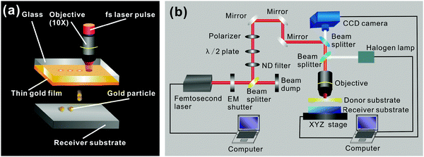
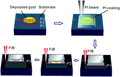
In these experiments, we used a commercial femtosecond laser system (Coherent) delivering laser pulses at a central wavelength of 800 nm, with a maximum pulse energy of 4 mJ, and a pulse duration of 50 fs at the maximum repetition rate of 1 kHz. A 60 nm gold film donor layer, coated on a 320 μm thick glass substrate, was fabricated by magnetron sputtering and was used for the laser transfer of molten submicron gold droplets. To obtain submicron gold droplets having a diameter of ∼800 nm, single fs laser pulses with an energy of ∼0.7 μJ were focused using a microscope objective (Olympus) with ×10 magnification and a numerical aperture (NA) of 0.3 through the glass onto the thin gold donor film (see Fig. 1a). The substrate that received the droplets was placed close to the gold coated glass at distances of <10 μm, 60 μm and 120 μm. The donor substrate and the receiver substrate were placed on an XYZ stage and moved horizontally at a velocity of 0.2 mm s−1. The femtosecond laser pulse repetition rate was set to 20 Hz to ensure that individual pulses irradiated a fresh gold area as shown in Fig. 1a. In Fig. 1b we show a detailed schematic of the experimental set-up. A neutral density (ND) filter and a λ/2 plate, together with a polarizer, were set up to continuously attenuate the incident laser radiation. The laser and light from a halogen lamp entering the objective are coaxial, so a CCD camera can be used to check whether the interface between the gold film and the glass is at the focal plane of the objective. All processes were carried out in air at atmospheric pressure.Imaging with a high speed camera is traditionally used to capture the side or bottom views of the droplet as it spreads or splashes during impact.3,16,24–26 However, it is difficult to obtain clear images of submicron size high velocity droplets using this technique. Instead, we use SEM (TESCAN Inc.) images of solidified submicron gold droplets after deposition to see whether splashing occurs after hitting the dry solid surface. Details of the structure inside the solidified droplets were analysed by cross-sectioning the solidified gold droplets by FIB (TESCAN Inc.). Fabrication procedures involved in obtaining metal cross-sections are shown in Fig. 2. A platinum coating was deposited prior to FIB milling to protect the gold surface upon exposure to the Ga+ beam. FIB milling of the deposited gold proceeded vertically as shown in Fig. 2.
In order to investigate how the heat transfer rate between the droplet and the substrate affects the splashing result, four different types of substrates were used as the receptors for transferred metal: (1) single crystal silicon with a thickness of 500 μm and an average surface roughness of 0.4 nm; (2) a 60 nm gold film coated on a 300 μm thick glass and an average surface roughness of 1.2 nm; (3) a 50 nm gold film coating on a silicon wafer with a 5 nm chromium adhesion layer and an average surface roughness of 4.1 nm (PELCO); and (4) a polished gold foil with a thickness of 30 μm and an average surface roughness of 6.0 nm.
The same laser parameters and the donor substrate were used in each experiment in order to reproduce the droplet size, the initial speed and the temperature of droplets ejected from the gold film. Experimental conditions were maintained for deposition of at least 20 individual droplets, but high magnification images will be shown for only one of these droplets.
Results
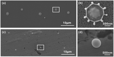
Fig. 3a shows the morphology of a periodic array of solidified metal particles deposited using the fsLIFT technique after impacting and spreading on the surface of a 50 nm thick gold film coating on silicon at a droplet flight distance of 60 μm. A magnified view of a transferred gold particle is shown in Fig. 3b. Splashing morphologies of each of the metal deposits were almost same, forming symmetric crown-like splashes, indicating that uniform splashing behavior can be obtained when the irradiation conditions are standardized. The particles deposited on the surface of polished gold foil are shown in Fig. 3c, with a magnified view shown in Fig. 3d. Under these conditions, the metal deposits were all spherical with a diameter of ∼800 nm, indicating the droplet size under all deposition conditions.As noted elsewhere, the velocity of molten submicron droplets ejected from a gold film after irradiation by a femtosecond laser pulse is tens of meters per second.27 Due to the drag force in air and convective cooling, the velocity and temperature of such droplets will decrease prior to the impact on the receptor substrate. Neglecting quantum effects and the Brownian motion of droplets during flight, the drag force, f, acting on these droplets in air is
| f = −kR3v | (1) |
 | (2) |
 | (3) |
The reduction in droplet temperature prior to impact due to heat transfer to ambient air is30
 | (4) |
 | (5) |
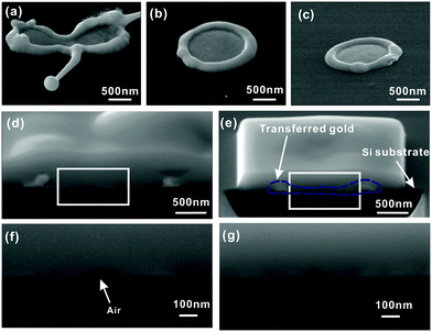
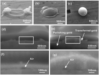
Fig. 4 shows the effect of different flight distances on the impact of 800 nm diameter molten gold droplets on a silicon surface. At high impact energy (z < 10 μm, as shown in Fig. 4a), splashing produces an irregular lamella-like morphology and a small droplet is ejected from the lamella. No splash was visible at smaller impact energies (z = 60 μm and 120 μm, as shown in Fig. 4b and c, respectively). In this case, the lamella did not become unstable but uniformly spreads to form a thin disk-like splat structure with a thicker smooth rim at the periphery. Although the droplet temperature decreases as the flight distance increases, these results indicate that the submicron gold droplet was still liquid after travelling the maximum distance of 120 μm.
Fig. 5 shows the morphology of gold droplets after impacting on a polished gold foil, >35 times thicker than the diameter of the gold droplet. Under these conditions, the gold foil has large mass compared to that of the droplet, and behaves like a bulk material. At high impact energy, the molten gold droplet is observed to splash on the gold substrate as shown in Fig. 5a. However, no splashing occurred at intermediate impact energy (Fig. 5b), although the periphery exhibits the effect of instabilities on the liquid surface. At low impact energy (Fig. 5c), the droplet remains spherical after impact as droplet solidification is rapid, inhibiting spreading.
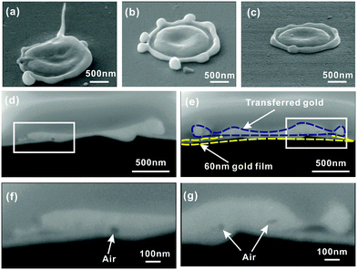
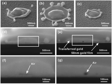
The above results clearly show that heat transfer to the substrate plays an important role in determining the spreading and splashing of a molten submicron droplet. The gold coated glass substrate and gold coated silicon substrates were used to obtain different heat transfer rates without changing the wetting conditions. Fig. 6 and 7 show images of molten submicron droplets impacting on gold coated glass and gold coated silicon, respectively. The splashing behaviors in Fig. 6 and 7 are seen to be very similar and are not influenced by surface roughness. In both Fig. 6 and 7, asymmetric splashes with irregular edges were found at high impact energy and result from the ejection of the lamella. At intermediate impact energy (Fig. 6b and 7b), symmetric splashes with crown-like outward propagating drops are observed (similar to the morphology shown in Fig. 3b), while at low impact energy (Fig. 6c and 7c), no splashing was visible and random bumps formed at the edges of the ring. These bumps can be associated with the initial stages in the development of crown-like structures seen at higher impact energy. An observation of splashing morphology on the four substrates at different droplet flight distances shows that splashing is enhanced for the submicron droplet impact on gold coated silicon and gold coated glass compared to the impact on silicon. A summary of splashing behaviors of the sub-micron gold droplet impacting on different substrates with different flight distances is shown in Table 1.
| Substrate | Average surface roughness (nm) | Droplet flight distance (μm) | Splashing or nota |
|---|---|---|---|
| a Observational results of SEM in describing whether sub-micron gold droplets are splashed or not on that particular condition. Triangles mean splashing observed and circles mean no splashing observed. | |||
| Silicon | 0.4 | <10 | ▼ |
| ∼60 | ● | ||
| ∼120 | ● | ||
| Polished gold foil | 6.0 | <10 | ▼ |
| ∼60 | ● | ||
| ∼120 | ● | ||
| Gold coated glass | 1.2 | <10 | ▼ |
| ∼60 | ▼ | ||
| ∼120 | ● | ||
| Gold coated silicon | 4.1 | <10 | ▼ |
| ∼60 | ▼ | ||
| ∼120 | ● | ||
Cross-sections of submicron droplets after impact and sectioning using FIB are shown in Fig. 4–7. Entrapped air bubbles or air layers, as indicated by arrows, were observed at the center of the droplet–substrate interface. Air layers and bubbles entrapped between micron-sized room temperature droplets and a solid surface have been seen in previous studies and it is evident that these structures play a significant role in determining the overall structures remaining after impact.21,31,32 A direct measurement of the air layer has been obtained using optical interferometry. However, this technique is not available for submicron droplets due to diffraction. Entrapped air layers and air bubbles in our experiments are believed to be firm evidence for the existence of an air layer during impact. This is the first time that such entrapped structures have been detected after impact quenching of molten submicron droplets. Their presence indicates that, as for molten submicron droplets, the onset of deformation in these droplets arises from a rapid pressure increase in the air layer trapped between the liquid and the solid surface during impact.
Discussion
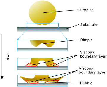
Other studies have demonstrated that splashing is diminished for room temperature droplets when the material readily wets the surface.18,19 In the current study, we find, however, that splashing is enhanced on a gold coated silicon substrate relative to a silicon substrate (Fig. 4b and Fig. 7b), which is an opposite effect. We suggest that a hot droplet/cold substrate combination increases the role of heat transfer allowing heat transfer to become more important than surface wetting. The following section will discuss this heat transfer in some detail.In a model based on splashing induced by the trapped air layer,17,20,32,33 the droplet approaches close to the substrate and initially forms an air dimple due to compression of the ambient gas between the droplet and the surface. Once the droplet touches the substrate, a viscous boundary layer develops near the contact region, as shown in Fig. 8. Viscous drag decreases the horizontal flow coming from the center of the droplet, which diverts the flow away from the surface and lifts the lamella.32 Instability in the lamella during liftoff leads to the ejection of the material and splashing. To describe this process, we consider two contributions to the stress on the expanding liquid layer: ΣG due to the restraining pressure of the air layer, which acts to deflect the material upward, and ΣL due to surface tension, which keeps the liquid layer intact.20,32 Thus droplet splashing results from the competition between these two forces, with ΣG promoting splashing through sheet ejection and ΣL suppressing this effect. As described by Xu et al. in ref. 20, ΣG/ΣL is approximately
 | (6) |
The physical quantities in eqn (6) are evaluated at room temperature and are assumed to be constant. They would vary from these values only when a temperature gradient exists between the droplet and the substrate. To simplify, we only consider heat transfer between the viscous boundary layer and the substrate. From ref. 30 the temperature of the viscous boundary layer is
 | (7) |
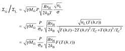 | (8) |
 | (9) |
Comparing the cross-sectional images of metal droplets deposited on different substrates, we see that the residual top on the impacted droplet on a gold foil (Fig. 5e) is much more pronounced than that on gold coated silicon or glass (Fig. 6e and 7e). The droplet on silicon had the smallest residual top (see Fig. 4e). The height of this residual top on the droplet is affected by the heat transfer efficiency between the droplet and the substrate. A higher residual top on the droplet implies a larger heat transfer rate to the substrate, so that less liquid can spread from the center to the edges before the center of the metal can solidify. Based on the above analytical model, it is apparent that submicron gold droplets exhibit increased splashing on gold coated silicon and gold coated glass substrates relative to silicon substrates because of the higher heat transfer rate for gold–gold contact compared to that at the gold–silicon interface. The experimental data also show that, if heat transfer is too efficient, then the entire droplet freezes too quickly to permit significant flow/ejection of metal from the cooling droplet. Under these conditions, splashing does not occur, as shown in Fig. 5b and c.
Conclusions
We have developed a new technique based on femtosecond laser induced forward transfer (fsLIFT) and focused ion beam (FIB) milling to investigate the splashing behavior of molten submicron droplets. This new method has shown that an air layer and/or air bubbles become entrapped underneath submicron sized droplets during impact. From a comparison of splashing characteristics under standardized conditions on different substrates, we find that heat transfer between the molten submicron droplet and the solid substrate is the primary factor controlling the evolution of splashing morphology. Splashing is enhanced at higher impact energy, but ≤6 nm average surface roughness and the wettability of the substrate surface are not as important as heat transfer to the substrate on a submicron scale. These experiments, supported by an analytical model, show that higher droplet–substrate heat transfer rates facilitate splashing.Acknowledgements
This work was supported by National Natural Science Foundation of China (Grant No. 51375261, 51405258, and 51520105007), The Natural Science Foundation of Beijing (Grant No. 3132020), The Specialized Research Fund for Doctoral Program of Higher Education (Grant No. 20130002110009) and Tsinghua University Initiative Scientific Research Program (Grant No. 2010THZ 02-1 and 2013Z02-1).References
- K. VanEvery, M. M. Krane, R. Trice, H. Wang, W. Porter, M. Besser, D. Sordelet, J. Ilavsky and J. Almer, J. Therm. Spray Technol., 2011, 20, 817–828 CrossRef CAS.
- M. Vaezi, H. Seitz and S. Yang, Int. J. Adv. Des. Manuf. Technol., 2013, 67, 1721–1754 CrossRef.
- U. Zywietz, A. B. Evlyukhin, C. Reinhardt and B. N. Chichkov, Nat. Commun., 2014, 5, 3402 Search PubMed.
- L. Yang, C.-y. Wang, X.-c. Ni, Z.-j. Wang, W. Jia and L. Chai, Appl. Phys. Lett., 2006, 89, 161110 CrossRef.
- A. I. Kuznetsov, A. B. Evlyukhin, M. R. Gonçalves, C. Reinhardt, A. Koroleva, M. L. Arnedillo, R. Kiyan, O. Marti and B. N. Chichkov, ACS Nano, 2011, 5, 4843–4849 CrossRef CAS PubMed.
- A. Kuznetsov, R. Kiyan and B. Chichkov, Opt. Express, 2010, 18, 21198–21203 CrossRef CAS PubMed.
- D. P. Banks, C. Grivas, J. D. Mills, R. W. Eason and I. Zergioti, Appl. Phys. Lett., 2006, 89, 193107 CrossRef.
- P. Papakonstantinou, N. Vainos and C. Fotakis, Appl. Surf. Sci., 1999, 151, 159–170 CrossRef CAS.
- S. Bera, A. Sabbah, J. Yarbrough, C. Allen, B. Winters, C. G. Durfee and J. A. Squier, Appl. Opt., 2007, 46, 4650–4659 CrossRef CAS PubMed.
- A. Narazaki, T. Sato, R. Kurosaki, Y. Kawaguchi and H. Niino, Appl. Phys. Express, 2008, 1, 057001 CrossRef.
- L. Koch, A. Deiwick, S. Schlie, S. Michael, M. Gruene, V. Coger, D. Zychlinski, A. Schambach, K. Reimers, P. M. Vogt and B. Chichkov, Biotechnol. Bioeng., 2012, 109, 1855–1863 CrossRef CAS PubMed.
- M. L. Tseng, Y.-W. Huang, M.-K. Hsiao, H. W. Huang, H. M. Chen, Y. L. Chen, C. H. Chu, N.-N. Chu, Y. J. He and C. M. Chang, ACS Nano, 2012, 6, 5190–5197 CrossRef CAS PubMed.
- W. T. Chen, M. L. Tseng, C. Y. Liao, P. C. Wu, S. Sun, Y.-W. Huang, C. M. Chang, C. H. Lu, L. Zhou and D.-W. Huang, Opt. Express, 2013, 21, 618–625 CrossRef PubMed.
- M. L. Tseng, C. M. Chang, B. H. Chen, Y. W. Huang, C. H. Chu, K. S. Chung, Y. J. Liu, H. G. Tsai, N. N. Chu, D. W. Huang, H. P. Chiang and D. P. Tsai, Nanotechnology, 2012, 23, 444013 CrossRef PubMed.
- L. Xu, L. Barcos and S. R. Nagel, Phys. Rev. E: Stat., Nonlinear, Soft Matter Phys., 2007, 76, 066311 CrossRef.
- A. Latka, A. Strandburg-Peshkin, M. M. Driscoll, C. S. Stevens and S. R. Nagel, Phys. Rev. Lett., 2012, 109, 054501 CrossRef PubMed.
- G. Riboux and J. M. Gordillo, Phys. Rev. Lett., 2014, 113, 024507 CrossRef PubMed.
- K. Yokoi, Soft Matter, 2011, 7, 5120–5123 RSC.
- C. Duez, C. Ybert, C. Clanet and L. Bocquet, Nat. Phys., 2007, 3, 180–183 CrossRef CAS.
- L. Xu, W. W. Zhang and S. R. Nagel, Phys. Rev. Lett., 2005, 94, 184505 CrossRef PubMed.
- P. Tsai, M. H. W. Hendrix, R. R. M. Dijkstra, L. Shui and D. Lohse, Soft Matter, 2011, 7, 11325–11333 RSC.
- S. D. Aziz and S. Chandra, Int. J. Heat Mass Transfer, 2000, 43, 2841–2857 CrossRef.
- C. W. Visser, Y. Tagawa, C. Sun and D. Lohse, Soft Matter, 2012, 8, 10732–10737 RSC.
- M. H. W. Hendrix, R. Manica, E. Klaseboer, D. Y. C. Chan and C.-D. Ohl, Phys. Rev. Lett., 2012, 108, 247803 CrossRef PubMed.
- J. C. Bird, R. Dhiman, H.-M. Kwon and K. K. Varanasi, Nature, 2013, 503, 385–388 CrossRef CAS PubMed.
- V. Bergeron, D. Bonn, J. Y. Martin and L. Vovelle, Nature, 2000, 405, 772–775 CrossRef CAS PubMed.
- C. Unger, J. Koch, L. Overmeyer and B. N. Chichkov, Opt. Express, 2012, 20, 24864–24872 CrossRef CAS PubMed.
- S.-C. Tseng, C.-C. Yu, D.-C. Lin, Y.-C. Tseng, H.-L. Chen, Y.-C. Chen, S.-Y. Chou and L. A. Wang, Nanoscale, 2013, 5, 2421–2428 RSC.
- C. M. Rouleau, A. A. Puretzky and D. B. Geohegan, Appl. Phys. Lett., 2014, 105, 213108 CrossRef.
- S. Patankar, Numerical heat transfer and fluid flow, CRC Press, 1980 Search PubMed.
- P. Tsai, R. C. A. van der Veen, M. van de Raa and D. Lohse, Langmuir, 2010, 26, 16090–16095 CrossRef CAS PubMed.
- S. Mandre and M. P. Brenner, J. Fluid Mech., 2012, 690, 148–172 CrossRef.
- C. W. Visser, P. E. Frommhold, S. Wildeman, R. Mettin, D. Lohse and C. Sun, Soft Matter, 2015, 11, 1708–1722 RSC.
- S. Sugden, J. Chem. Soc., Trans., 1924, 125, 32–41 RSC.
| This journal is © The Royal Society of Chemistry 2016 |

