 Open Access Article
Self-powered fluorescence display devices based on a fast self-charging/recharging battery (Mg/Prussian blue)†
Hui
Zhang
ab,
You
Yu
ab,
Lingling
Zhang
ab,
Yiwen
Zhai
ab and
Shaojun
Dong
*ab
aState Key Laboratory of Electroanalytical Chemistry, Changchun Institute of Applied Chemistry, Chinese Academy of Science, Changchun, Jilin 130022, P. R. China. E-mail: dongsj@ciac.ac.cn
bUniversity of Chinese Academy of Sciences, Beijing, 100049, P. R. China
First published on 5th July 2016
Abstract
Stimuli-responsive (such as voltage and/or light) fluorescence display systems have attracted particular attention in their promising fields of application. However, there are few examples of self-powered fluorescence display devices. Here we designed and fabricated a self-powered fluorescence display device based on a fast-charging/recharging battery. The specially designed battery was composed of a Prussian blue (PB) cathode and a magnesium metal anode with a high theoretical redox potential difference (∼2.8 V). Moreover, smartly adding a trace amount of NaClO in the electrolyte could realize oxidizing PW to PB ∼480 times faster than when oxidizing without NaClO, leading to the fast self-charging and high power density (maximum power density of 13.34 mW cm−2, about two to three orders of magnitude larger than previous bio-fuel cells) of the Mg/PB battery. Most importantly, PB was used as not only the cathodic catalyst but also as an electrochromic material, making it possible to construct a self-powered and rechargeable electrochromic fluorescence display with only two electrodes. Besides, fluorescent [Ru(bpy)3]2+-doped silica nanoparticles (Ru@SiO2), were selected as the fluorescence resonance energy transfer (FRET) donor to match PB (FRET acceptor). To the best of our knowledge, we demonstrated a self-powered and rechargeable electrochromic fluorescence display with only two electrodes for the first time.
Introduction
Stimuli-responsive (such as voltage and/or light) fluorescence display systems have attracted particular attention in their promising fields of application.1 Generally, the fluorescence switching devices are based on optical coupling between the emission spectra of the selected fluorescent molecule and the absorption spectra of the electrochromic (or photochromic) material. Either a inner filter effect (IFE)2 or fluorescence resonance energy transfer (FRET)3 would occur between the fluorescent molecule (FRET donor) and the electrochromic (or photochromic) material (FRET acceptor), causing fluorescence quenching of the fluorescent molecule. Under stimulation, the electrochromic (or photochromic) material would display different absorbances, followed by variation of the fluorescence intensity. During the past decades, some fascinating research has been done. Jovin's group1a devised a family of photoswitchable QDs in which the donor–acceptor distance was varied systematically by attaching QD cores and photochromic diheteroarylethene groups via linkers of different lengths. Zhu's group1b synthesized a new molecular structure of a trident perylenemonoimide modified by three photochromic dithienylethenes (1 donor–3 acceptors) with a high fluorescence switching speed. Besides, our group have also done some research into stimuli-responsive fluorescence displays,4 including photo-chem-electrotriggered three-state fluorescence switching.5 Nevertheless, most previous systems need external stimulation to operate, causing additional energy consumption. There were rare self-powered electrochromic devices,6 which had received much attention. However, those few self-powered electrochromic devices usually involved three electrodes (one electrochromic electrode, one anode and one cathode), which greatly enhanced the manufacturing process complexity.To realize a self-powered electrochromic fluorescence device with less than three (only two) electrodes, it is necessary to integrate the electrochromic electrode with the anode (or cathode). In this regard, Prussian blue (PB), an excellent electrochromic material, is a good alternative, which can also be used as the cathodic catalyst, leading to the possibility of designing bifunctional devices.7 Moreover, self-charging batteries are of great interest due to the emerging problems of the energy crisis and environmental pollution.8 A self-charging and rechargeable PB battery makes it possible to realize a self-powered fluorescence display with only two electrodes (PB could function as a cathode as well as an electrochromic electrode). However, the reported PB battery needs days to self-charge,9 and so could hardly be applied in fluorescence displays.
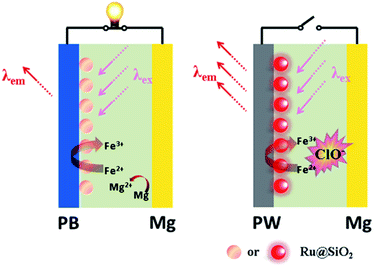
Here we demonstrate a self-powered electrochromic fluorescence display based on a fast self-charging and rechargeable Mg/PB battery (Fig. 1). The device was composed of a PB cathode electrochemically deposited on a fluorine-doped tin oxide (FTO) glass, and a magnesium metal anode. Compared to metallic lithium, which is usually applied in Li-ion batteries, metallic magnesium is free from inherent poor stability and safety.10 Moreover, a strong oxidant solution, containing a trace amount of NaClO, was used as electrolyte, which could oxidize the colorless PW to PB within a few minutes, realizing the fast self-charging of the Mg/PB battery. In addition, a fluorescent system of [Ru(bpy)3]2+-doped silica nanoparticles (Ru@SiO2), immobilized onto the surface of PB, was selected as the FRET donor, since its emission bands overlap well with the absorption spectrum of PB and it could maintain its fluorescence in the strong oxidizing electrolyte. Lastly, Nafion was dropped on the surface of Ru@SiO2 to avoid the leaking of Ru@SiO2. Thus, an electrochromic fluorescence display, PB/Ru@SiO2/Nafion, was constructed successfully, and the fluorescence could be switched “on” and “off” by simply “connecting” and “disconnecting” PB and Mg. For the first time, a self-powered electrochromic fluorescence display with only two electrodes was proposed.
Experimental
Materials and methods
Triton X-100 and NaClO were purchased from Sigma. Tris(2,2′-bipyridyl)dichlororuthenium(II)hexahydrate (Ru(bpy)3Cl2·6H2O) was obtained from Aldrich. Tetraethylorthosilicate (TEOS) was bought from Beijing Yili Chemical Reagent. K2HPO4·3H2O and KH2PO4 were used to prepare the phosphate buffer. All of the other chemicals were of analytical grade and were used without further purification. Ultrapure water (>18 MΩ) from Water Purifier (Sichuan Water Purifier Co., Ltd., China) was utilized throughout the experiments. The single-side conductive FTO chips (transmittance > 83%, sheet resistance < 15 Ω sq−1) were purchased from Zhuhai Kaivo Optoelectronic Technology Co., Ltd., China.The absorption measurements were carried out on a Cary 500 UV-vis-NIR spectrometer (Varian). Photoluminescence measurements were conducted with a Fluoromax-4 spectrofluorometer (Horiba Jobin Yvon Inc., France); the excitation and emission slit widths were 5 nm. Electrochemical experiments were performed on a CHI 660 electrochemical workstation.
Synthesis of PB film
Before modification, the FTO glasses (trapezoid, (0.570 + 0.840)/2 × 5.300 cm2) were cleaned with acetone, ethanol and water in an ultrasonic bath each for 10 min. Then the FTO chips were immersed in an activation solution containing 1![[thin space (1/6-em)]](https://www.rsc.org/images/entities/char_2009.gif) :
:![[thin space (1/6-em)]](https://www.rsc.org/images/entities/char_2009.gif) 1 (v/v) ethanol/NaOH (1 M) for 15 min. After being thoroughly rinsed with water and dried with nitrogen, the FTO sheets were electropolymerized with PB by applying a constant potential of 0.4 V for 500 s. An aqueous solution which consisted of 0.1 M KCl, 0.1 M HCl, 2.5 mM K3[Fe(CN)6] and 2.5 mM FeCl3 was employed as the electrolyte for PB electrochemical deposition.11 Meanwhile the FTO chip, Pt sheet and Ag/AgCl (saturated KCl) were utilized as the working electrode, counter electrode and reference electrode, respectively. Finally, the as-prepared PB electrodes were dried at 100 °C for 5–6 h after being thoroughly rinsed with water, and stored in a centrifuge tube shielded from light.
1 (v/v) ethanol/NaOH (1 M) for 15 min. After being thoroughly rinsed with water and dried with nitrogen, the FTO sheets were electropolymerized with PB by applying a constant potential of 0.4 V for 500 s. An aqueous solution which consisted of 0.1 M KCl, 0.1 M HCl, 2.5 mM K3[Fe(CN)6] and 2.5 mM FeCl3 was employed as the electrolyte for PB electrochemical deposition.11 Meanwhile the FTO chip, Pt sheet and Ag/AgCl (saturated KCl) were utilized as the working electrode, counter electrode and reference electrode, respectively. Finally, the as-prepared PB electrodes were dried at 100 °C for 5–6 h after being thoroughly rinsed with water, and stored in a centrifuge tube shielded from light.
Preparation of the Mg/PB battery and electrochemical measurements
The battery was composed of a PB cathode and a metallic Mg anode. The slim Mg rod was wrapped with insulation tape with a section (0.192 × 0.312 cm2) uncovered. A strong oxidant solution composed of 0.025 M NaClO, 1 M KCl, and 0.1 M phosphate buffer (pH 6) was used as the electrolyte. The charging and discharging process of the Mg/PB battery was achieved by disconnecting and connecting PB and Mg electrodes. When detecting the open circuit potential and power of the Mg/PB battery, Mg served as both the counter and reference electrode. The uncovered section of Mg rod was polished before each test.Synthesis of Ru@SiO2 nanoparticles
The Ru@SiO2 nanoparticles were prepared as previously described.12 Briefly, cyclohexane (7.5 mL), Triton X-100 (1.77 mL), 1-hexanol (1.8 mL) and water (340 μL) were mixed together at the beginning. Then [Ru(bpy)3]2+ (0.1 M, 80 μL) was added under magnetic stirring. After introduction of TEOS (100 μL), the mixture solution was kept stirring for 30 min. Finally, a polymerization reaction was initiated by injecting ammonia (25%, 60 μL). After the reaction was completed within 24 h, the Ru@SiO2 nanoparticles were isolated using acetone, and washed with ethanol and water several times. The orange precipitates were dried under 80 °C temperature to obtain completely dry products.Preparation of PB/Ru@SiO2/Nafion film and optical measurements
A Ru@SiO2 (10 μL, 1 mg mL−1) aqueous solution was dropped on the surface of PB. After being dried at ambient temperature, Nafion (10 μL, 0.2%) was dropped on the surface of Ru@SiO2 to avoid the leaking of Ru@SiO2. In the Mg/PB battery system, the PB/Ru@SiO2/Nafion film functioned as the fluorescence display. The switch on and off of the fluorescence display was realized by connecting and disconnecting the PB cathode and the Mg anode.The online photoluminescence measurements were performed on a home built cuvette.13 The cuvette was capped with a Teflon plate to support the electrodes, with the PB film glasses kept at a 45 angle to the excitation light source and the detector (the detector is vertical to the excitation light source in a spectrofluorometer). At the same time the absorption measurements were conducted with another Teflon plate, and the PB film electrode was kept vertical to the excitation light path (the detector is in the excitation light path in a UV-vis-NIR spectrometer).
Results and discussion
The Mg/PB battery
The redox potential of the electrode reaction was demonstrated firstly.| Mg → Mg2+ + 2e−, −2.37 V (vs. SHE) |
| PB → PW, +0.43 V (vs. SHE) |
The oxidation potential of PB was much higher than Mg, indicating the feasibility of Mg/PB battery. The great redox potential difference (∼2.8 V) might promise wonderful battery behavior of the Mg/PB system.
The proposed battery system was composed of a PB cathode electrochemically deposited on a single-side conductive FTO glass and a Mg metal anode (0.192 × 0.312 cm2). Briefly, the PB film was polymerized in a mixture of K3[Fe(CN)6] and FeCl3 as the electrolyte. The original transparent FTO exhibited a blue color after the electrodeposition procedure, confirming the successfully preparation of the PB film. The morphology and structure of these PB chips were characterized using scanning electron microscopy (SEM). A uniform surface was observed (Fig. S1†). Moreover, while investigating its electrochromic properties, PB displayed outstanding reversibility, and excellent long-time stability (Fig. S2†), which laid a favorable foundation for repeatable chemical recovery from PW to PB (vide infra).
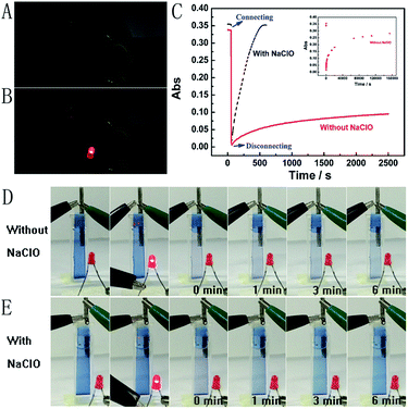
Next, the Mg/PB battery was assembled by connecting the PB cathode and Mg anode with 1 M KCl and 0.1 M phosphate buffer (pH 6) as the electrolyte. PB changed from blue to colourless to form PW on connecting PB and Mg, which was the discharging process of the Mg/PB battery (Fig. 2C, red curve). The absorbance of PB was decreased by 91.7% in the initial 4.2 s and 97.8% in total over 10.0 s. On disconnecting PB and Mg, PW was oxidized to form PB by dissolved oxygen in the solution and the transparent PW turned to blue, which showed the charging process of the battery. However, this charging process was too slow. For 26.1% and 82.7% absorbance increases (within the total 97.8% absorbance decrease obtained in the initial 10 s), the corresponding recovery times were 40.0 min and 42.8 h, respectively.
The spontaneous oxidation of PW to PB depending on the dissolved oxygen was too slow, therefore the Mg/PB battery could not be used as a self-charging power source. To solve this problem, we argued to increase the oxidability of the electrolyte solution. And a trace amount of NaClO could be greatly helpful. By means of an optimization test, the final electrolyte solution was composed of 0.025 M NaClO, 1 M KCl, and 0.1 M phosphate buffer (pH 6). In these conditions (Fig. 2C, black curve), the absorbance of PB was decreased by 95.1% in the initial 10.0 s (connecting PB and Mg, discharging process, PB to PW, bleaching) and increased by 90% in the next 6.24 min (disconnecting PB and Mg, charging process, PW to PB, colouration). The corresponding movies are available in ESI Movies 1 and 2,† which visually show the different recovery times of PW in the electrolyte with and without NaClO. Compared with the Mg/PB battery without NaClO electrolyte (colouration for 82.7%, 42.8 h), the proposed PB system exhibited a notably high colouration speed. It only needed 5.35 min to undergo colouration of 82.7%, ∼480 times faster than the battery without NaClO. And a rapid colouration speed means a quick charging process. Considering our proposed battery is self-charging, the ability for fast self-charging is prominent and favourable for practical applications. This fascinating character was attributed to the strong oxidant NaClO in the electrolyte solution. NaClO could oxidize PW to PB quickly. Meanwhile, the absorbance of PB could almost 100% recover to its original value, that is to say, the Mg/PB battery could fully self-charge within ∼6 minutes. Simultaneously, the bleaching speed (bleaching over 95%, 10 s) in a solution with and without NaClO is comparable, and negligible interference from NaClO was confirmed. By the way, some other oxidants, such as H2O2 and (NH4)2S2O8, were also effective to replace NaClO in the system (Fig. S3†). Although more optimization of experimental conditions (the pH, the temperature or the concentration of the oxidant) should be done to get a satisfactory self-charging speed, the universality of the design by introducing an oxidant into battery electrolyte is a very promising prospect.
The open circuit potential measurements were taken in a two-electrode configuration with the slim Mg rod serving as both the counter and reference electrode. The measured open circuit potential of the Mg/PB battery was 2.50 V, which is higher than for previously reported electrochromic batteries (1.26 V;9 0.87 V).14 And just one battery could light up a red LED (Fig. 2B). To elucidate more about the high open circuit potential, some detailed experiments were carried out. The cathode (PB) and anode (Mg) potentials of the battery were 0.68 V and 1.82 V, respectively. Strangely, according to the previous reports,7a,9 the cathode (PB) potential should be approximately 0.35 V (vs. Ag/AgCl). We suggested that the strong oxidant electrolyte solution might account for this difference. To verify this hypothesis, the cathode and anode potential were detected once again in a electrolyte without NaClO (only containing 1 M KCl and 0.1 M phosphate buffer (pH 6)). Then the cathode and anode potentials were 0.37 V and 1.78 V, respectively. Inspired by the observed experimental facts, it became evident that NaClO played a momentous role in increasing the cathode potential.
Another significant experimental parameter for batteries is power. Taking the small active area of the trapezoidal PB film ((0.610 + 0.840)/2 × 3.130 cm2) into account, the power of this Mg/PB battery was detected using a method normally used in biofuel cells.15 In a quiescent solution, the maximum current density of the battery was 7.85 mA cm−2 and the maximum power density was 13.34 mW cm−2 (about two to three orders of magnitude larger than previous bio-fuel cells)16 at 1.70 V of the cell voltage, according to the geometrical surface of the Mg electrode (Fig. 3). For comparison, the power density was also monitored in an electrolyte without NaClO, since NaClO may be helpful to improve the power output. In that case, the maximum power density was decreased to nearly 3 mW cm−2. Thus, NaClO not only accelerated the oxidation of PW, making the Mg/PB battery a fast self-charging one, but also was involved in augmenting the open circuit potential and power density of this battery. Table S1† summarizes the differences in the battery behavior between the electrolyte with and without NaClO.
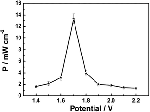 | ||
| Fig. 3 Dependence of the power density on the cell voltage for the assembled Mg/PB battery in 0.025 M NaClO, 1 M KCl and 0.1 M phosphate buffer (pH 6) electrolyte, quiescent solution, under air. | ||
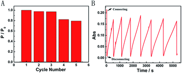
We further characterized the Mg/PB battery in terms of rechargeable acceptance ability. Fortunately, the apparent structure of PB did not present great changes after one discharging and charging cycle in an appropriate concentration of NaClO, which was confirmed via the SEM images of PB before and after one cycle. After three cycles, the recovered Mg/PB battery could still deliver a maximum power density of 12.96 mW cm−2, with a total loss of 3% compared with the first discharge process (Fig. 4A). In addition, the maximum power density decreased 21% after cycling five times. However, from the absorbance spectra, during seven cycles the Mg/PB battery could maintain over 80% of the original absorbance value before the test (Fig. 4B). Although the PW recovery process was slowing because of the consumption of NaClO, the maximum recovery time was still within 1000 s in the last (seventh) cycle.
The functioning mechanisms of the fast self-charging and rechargeable Mg/PB battery could be illustrated as follows (Fig. S4†): Mg is a highly active metal, showing strong reducibility. When connecting PB and Mg, Mg released electrons to form Mg2+ ions, and PB accepted electrons to form PW.
Half-cell reactions:
Anode
| Mg = Mg2+ + 2e− | (1) |
Cathode
| KFeIII[FeII(CN)6] (PB) + K+ + e− = K2FeII[FeII(CN)6] (PW) | (2) |
The overall cell reaction can be expressed as:
| 2KFeIII[FeII(CN)6] (PB) + 2K+ + Mg = 2K2FeII[FeII(CN)6] (PW) + Mg2+ | (3) |
The bleached device recovered its blue colour after being oxidized by NaClO; this charging process could be described by the following reaction:
| 2K2FeII[FeII(CN)6] (PW) + NaClO + 2H+ = 2KFeIII[FeII(CN)6] (PB) + 2K+ + NaCl + H2O | (4) |
It is worth noting that, the reaction (4) still exists even in the discharging process. Despite the coexistence of reactions (3) (PB to PW) and (4) (PW to PB), the reaction rate of (3) is much higher than that of (4). While connecting PB and Mg, reaction (3) is dominant and the colour variation of the FTO glass just could be observed from blue to transparent. The coexistence of reaction (3) with reaction (4) probably explained why NaClO is favourable for increasing the open circuit potential of the battery. Besides, dissolved oxygen in the solution is also active in the process.
Why would the trace amount of NaClO have an important effect on the oxidation of PW? To gain more insight, the redox potential during the recharging process was demonstrated.
| PW → PB, −0.43 V (vs. SHE) |
| HClO + H+ + 2e− → Cl− + H2O, +1.482 V (vs. SHE) |
The standard reduction potential of HClO was high in acidic solution. This probably explained why the trace amount of NaClO would greatly accelerate the oxidation of PW. By contrast, the spontaneous oxidation of PW to PB relying on dissolved oxygen was too slow, owing to the relatively weak oxidizability of oxygen.
The fluorescence displays
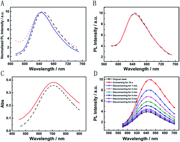
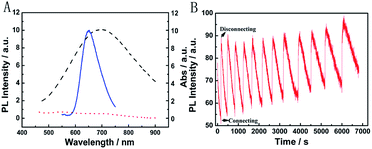
The broad market for electronics devices suffers from manufacturing process complexities. One solution is to develop integrated multifunctional devices. Since the PB device is not only a fast self-charging and rechargeable battery but also a smart electrochromic window, we could design a self-powered electrochromic fluorescence display with only two electrodes for the first time.The Ru@SiO2 functioned as the fluorescent molecule to match electrochromic PB. On the one hand, the emission peak of Ru@SiO2 was located at 649 nm and overlapped well with the absorption spectra of PB (Fig. 6A). So, effective IFE or FRET would occur when Ru@SiO2 was immobilized on the surface of PB. On the other hand, Ru@SiO2 could maintain its fluorescence in the strong oxidizing electrolyte solution, while some other fluorescent probes, such as nanoclusters or quantum dots were quenched. Lastly, Nafion was dropped on the surface of Ru@SiO2 to avoid the leaking of Ru@SiO2, thus an electrochromic fluorescence display, PB/Ru@SiO2/Nafion, was constructed successfully. Detailed experimental manipulation is revealed in the experimental section and the characterization is described in Fig. S5 to S8.† The average Ru@SiO2 crystalline sizes could be roughly calculated to be 79.0 ± 7.2 nm from the TEM image (Fig. S5†). Moreover, several control experiments have been performed. (1) Ru@SiO2 was stable both in an aqueous solution and on the surface of PB (Fig. 5A). (2) The fluorescence of Ru@SiO2/Nafion film (without PB) would not change while connecting with Mg (Fig. 5B). (3) The Ru@SiO2 on the surface of PB could not influence the absorbance of PB (Fig. 5C). (4) The emission peak of the PB/Ru@SiO2/Nafion film electrode decreased when the time of disconnecting with Mg was prolonged, and ∼6 min was required to restore the original value of fluorescence (Fig. 5D).
Fig. 6B presents the emission spectra variation of the PB/Ru@SiO2/Nafion film during charging and discharging cycles. Initially, the fluorescence of Ru@SiO2 was weak because of the strong absorbance of PB. When connecting PB and Mg (the discharging process), the absorbance of PB was drastically reduced and transparent PW was formed. Thus Ru@SiO2 returned to its intrinsic fluorescence intensity. When disconnecting PB and Mg afterwards (the charging process), PW was oxidized to PB, and the absorbance increased slowly, leading to the fluorescence decrease of Ru@SiO2 simultaneously. Detailed information about Fig. 6B is shown in Table S2.† The biggest fluorescence contrast and shortest recovery time were 63% and 290 s at the first cycle. The fluorescence contrast remained over 50% for six cycles with recovery times less than 500 s. Even after ten cycles, the PB/Ru@SiO2/Nafion film presented nearly 40% fluorescence contrast and a 660 s recovery time, indicating that the self-powered electrochromic fluorescence display is highly reversible and time-saving. The excellent performance of the self-powered electrochromic fluorescence display device can be attributed to the wonderful property of the Mg/PB battery as well as the efficient IFE and FRET between PB and Ru@SiO2. So far, the proposed device could be considered as a fast self-charging/recharging electrochromic fluorescence display with only two electrodes.
Conclusions
In summary, we have successfully realized a self-powered electrochromic fluorescence display based on a fast self-charging and rechargeable Mg/PB battery by introducing a trace amount of strong oxidant NaClO into the electrolyte. By simply connecting Mg and PB electrodes, just one battery could light up an LED. Afterwards, on disconnecting the Mg and PB electrodes, the battery could be self-charged within ∼6 min, ∼480 times faster than the battery without NaClO. During this process, PB contributed high power density and excellent cycling performance when evaluated as a cathode. The trace amount of NaClO played a central role in improving the battery behavior. Based on the encouraging performance of this battery, a self-powered electrochromic fluorescence device with only two electrodes was proposed for the first time. Further work might focus on the introduction of a gel or solid electrolyte to improve the device performance. Considering PW is transparent, and the Mg/PB battery could be a “half” transparent battery, our proposed device provides possibilities to develop transparent batteries used also as an electronic display screen. We anticipate that the proposed fast self-charging and rechargeable electrochromic fluorescence display would offer a solution to the emerging power supply problem of the next-generation, transparent portable electronic devices.Acknowledgements
This work is supported by the National Natural Science Foundation of China (No. 21375123) and the Ministry of Science and Technology of China (No. 2013YQ170585).Notes and references
- (a) S. A. Diaz, F. Gillanders, E. A. Jares-Erijman and T. M. Jovin, Nat. Commun., 2015, 6, 6036–6046 CrossRef CAS PubMed; (b) C. Li, H. Yan, L. X. Zhao, G. F. Zhang, Z. Hu, Z. L. Huang and M. Q. Zhu, Nat. Commun., 2014, 5, 5709–5719 CrossRef CAS PubMed; (c) A. Beneduci, S. Cospito, M. L. Deda and G. Chidichimo, Adv. Funct. Mater., 2015, 25, 1240–1247 CrossRef CAS; (d) G. F. Cai, M. Q. Cui, V. Kumar, P. Darmawan, J. X. Wang, X. Wang, A. L. Eh, K. Qian and P. S. Lee, Chem. Sci., 2016, 7, 1373–1382 RSC; (e) Y. M. Zhang, W. Li, X. J. Wang, B. Yang, M. J. Li and S. X. A. Zhang, Chem. Commun., 2014, 50, 1420–1422 RSC; (f) H. X. Gu, L. H. Bi, Y. Fu, N. Wang, S. Q. Liu and Z. Y. Tang, Chem. Sci., 2013, 4, 4371–4376 RSC; (g) I. L. Medintz, S. A. Trammell, H. Mattoussi and J. M. Mauro, J. Am. Chem. Soc., 2004, 126, 30–31 CrossRef CAS PubMed; (h) K. Nakamura, K. Kanazawa and N. Kobayashi, Chem. Commun., 2011, 47, 10064–10066 RSC; (i) L. Zhu, M. Q. Zhu, J. K. Hurst and A. D. Li, J. Am. Chem. Soc., 2005, 127, 8968–8970 CrossRef CAS PubMed; (j) Y. Kim, E. Kim, G. Clavier and P. Audebert, Chem. Commun., 2006, 3612–3614 RSC; (k) J. de Torres, P. Ferrand, G. Colas des Francs and J. Wenger, ACS Nano, 2016, 10, 3968–3976 CrossRef CAS PubMed; (l) P. Zrazhevskiy, L. D. True and X. Gao, Nat. Protoc., 2013, 8, 1852–1869 CrossRef CAS PubMed; (m) R. Yoshii, A. Hirose, K. Tanaka and Y. Chujo, J. Am. Chem. Soc., 2014, 136, 18131–18139 CrossRef CAS PubMed.
- L. Shang and S. J. Dong, Anal. Chem., 2009, 81, 1465–1470 CrossRef CAS PubMed.
- (a) J. J. Davis, H. Burgess, G. Zauner, S. Kuznetsova, J. Salverda, T. Aartsma and G. W. Canters, J. Phys. Chem. B, 2006, 110, 20649–20654 CrossRef CAS PubMed; (b) S. Buckhout-White, C. M. Spillmann, W. R. Algar, A. Khachatrian, J. S. Melinger, E. R. Goldman, M. G. Ancona and I. L. Medintz, Nat. Commun., 2014, 5, 5615–5630 CrossRef CAS PubMed; (c) Y. Y. Yuan, R. Y. Zhang, X. M. Cheng, S. D. Xu and B. Liu, Chem. Sci., 2016, 4245–4250 RSC.
- L. H. Jin, Y. X. Fang, D. Wen, L. Wang, E. K. Wang and S. J. Dong, ACS Nano, 2011, 5, 5249–5253 CrossRef CAS PubMed.
- Y. L. Zhai, Z. J. Zhu, C. Z. Zhu, J. Zhu, J. T. Ren, E. K. Wang and S. J. Dong, Nanoscale, 2013, 5, 4344–4350 RSC.
- (a) L. Bai, L. H. Jin, L. Han and S. J. Dong, Energy Environ. Sci., 2013, 6, 3015–3021 RSC; (b) M. Möller, N. Leyland, G. Copeland and M. Cassidy, Eur. Phys. J.: Appl. Phys., 2010, 51, 33205–33207 CrossRef.
- (a) A. Eftekhari, J. Power Sources, 2004, 126, 221–228 CrossRef CAS; (b) L. Zhang, H. B. Wu, S. Madhavi, H. H. Hng and X. W. Lou, J. Am. Chem. Soc., 2012, 134, 17388–17391 CrossRef CAS PubMed; (c) C. D. Wessells, R. A. Huggins and Y. Cui, Nat. Commun., 2011, 2, 550 CrossRef PubMed; (d) V. D. Neff, J. Electrochem. Soc., 1985, 132, 1382–1384 CrossRef CAS; (e) K. Itaya, I. Uchida and V. D. Neff, Acc. Chem. Res., 1986, 19, 162–168 CrossRef CAS; (f) S. Ferlay, T. Mallah, R. Ouahès, P. Veillet and M. Verdaguer, Nature, 1995, 378, 701–703 CrossRef CAS; (g) K. Itaya, N. Shoji and I. Uchida, J. Am. Chem. Soc., 1984, 106, 3423–3429 CrossRef CAS; (h) F. R. Wells, Nature, 1962, 195, 188–189 CrossRef CAS PubMed; (i) C. O'Dwyer, M. Szachowicz, G. Visimberga, V. Lavayen, S. B. Newcomb and C. M. Sotomayor Torres, Nat. Nanotechnol., 2009, 4, 239–244 CrossRef PubMed; (j) M. Hu, S. Furukawa, R. Ohtani, H. Sukegawa, Y. Nemoto, J. Reboul, S. Kitagawa and Y. Yamauchi, Angew. Chem., Int. Ed., 2012, 51, 984–988 CrossRef CAS PubMed; (k) M. Zhou, H. L. Wang and S. Guo, Chem. Soc. Rev., 2016, 45, 1273–1307 RSC; (l) A. Prabhu, J. Bobacka, A. Ivaska and K. Levon, Electroanalysis, 2013, 25, 1887–1894 CrossRef CAS; (m) M. Hu, A. A. Belik, M. Imura and Y. Yamauchi, J. Am. Chem. Soc., 2013, 135, 384–391 CrossRef CAS PubMed; (n) M. Hu, A. A. Belik, M. Imura, K. Mibu, Y. Tsujimoto and Y. Yamauchi, Chem. Mater., 2012, 24, 2698–2707 CrossRef CAS; (o) N. L. Torad, M. Hu, M. Imura, M. Naito and Y. Yamauchi, J. Mater. Chem., 2012, 22, 18261–18267 RSC.
- (a) M. C. Lin, M. Gong, B. Lu, Y. Wu, D. Y. Wang, M. Guan, M. Angell, C. Chen, J. Yang, B. J. Hwang and H. Dai, Nature, 2015, 520, 325–328 CrossRef PubMed; (b) B. Zhang and C. Cao, Nature, 2015, 517, 433–434 CrossRef CAS PubMed; (c) Y. S. Liu, Y. H. Li and C. Chen, Nature, 2015, 517, 145 CrossRef CAS PubMed; (d) Z. H. Gong, Nature, 2015, 517, 145 CrossRef CAS PubMed.
- J. M. Wang, L. Zhang, L. Yu, Z. H. Jiao, H. Q. Xie, X. W. Lou and X. W. Sun, Nat. Commun., 2014, 5, 4921–4927 CrossRef CAS PubMed.
- (a) P. S. E. Yeo and M. F. Ng, Chem. Mater., 2015, 27, 5878–5885 CrossRef CAS; (b) J. C. Knight, S. Therese and A. Manthiram, ACS Appl. Mater. Interfaces, 2015, 7, 22953–22961 CrossRef CAS PubMed; (c) C. B. Bucur, T. Gregory, A. G. Oliver and J. Muldoon, J. Phys. Chem. Lett., 2015, 6, 3578–3591 CrossRef CAS PubMed.
- L. H. Jin, Y. Fang, L. Shang, Y. Liu, J. Li, L. Wang, P. Hu and S. J. Dong, Chem. Commun., 2013, 49, 243–245 RSC.
- (a) L. H. Zhang and S. J. Dong, Anal. Chem., 2006, 78, 5119–5123 CrossRef CAS PubMed; (b) L. Wang, C. Y. Yang and W. H. Tan, Nano Lett., 2005, 5, 37–43 CrossRef CAS PubMed.
- (a) H. Zhang, Y. L. Zhai and S. J. Dong, Talanta, 2014, 129, 139–142 CrossRef CAS PubMed; (b) F. Montilla, I. Pastor, C. R. Mateo, E. Morallon and R. Mallavia, J. Phys. Chem. B, 2006, 110, 5914–5919 CrossRef CAS PubMed.
- M. Jayalakshmi and F. Scholz, J. Power Sources, 2000, 91, 217–223 CrossRef CAS.
- L. Deng, F. Wang, H. J. Chen, L. Shang, L. Wang, T. Wang and S. J. Dong, Biosens. Bioelectron., 2008, 24, 329–333 CrossRef CAS PubMed.
- (a) A. Le Goff, M. Holzinger and S. Cosnier, Cell. Mol. Life Sci., 2015, 72, 941–952 CrossRef CAS PubMed; (b) J. Gooding and W. R. Yang, Actual. Chim., 2008, 320, 85–89 Search PubMed; (c) P. Pinyou, A. Ruff, S. Poller, S. Ma, R. Ludwig and W. Schuhmann, Chem.–Eur. J., 2016, 22, 5319–5326 CrossRef CAS PubMed; (d) D. Faggion Junior, R. Haddad, F. Giroud, M. Holzinger, C. E. Maduro de Campos, J. J. Acuna, J. B. Domingos and S. Cosnier, Nanoscale, 2016, 8, 10433–10440 RSC; (e) D. P. Hickey, R. C. Reid, R. D. Milton and S. D. Minteer, Biosens. Bioelectron., 2016, 77, 26–31 CrossRef CAS PubMed.
Footnote |
| † Electronic supplementary information (ESI) available. See DOI: 10.1039/c6sc02347a |
| This journal is © The Royal Society of Chemistry 2016 |

