
 Open Access Article
 This Open Access Article is licensed under a Creative Commons Attribution-Non Commercial 3.0 Unported Licence
Gel permeation chromatography as a multifunctional processor for nanocrystal purification and on-column ligand exchange chemistry†
Yi
Shen
a,
Adam
Roberge
a,
Rui
Tan
a,
Megan Y.
Gee
a,
Dylan C.
Gary
b,
Yucheng
Huang
a,
Douglas A.
Blom
c,
Brian C.
Benicewicz
ac,
Brandi M.
Cossairt
b and
Andrew B.
Greytak
*ac
aDepartment of Chemistry and Biochemistry, University of South Carolina, Columbia, SC 29208, USA. E-mail: greytak@sc.edu
bDepartment of Chemistry, University of Washington, Seattle, WA 98195, USA
cUSC Nanocenter, University of South Carolina, Columbia, SC 29208, USA
First published on 25th May 2016
Abstract
This article illustrates the use of gel permeation chromatography (GPC, organic-phase size exclusion chromatography) to separate nanocrystals from weakly-bound small molecules, including solvent, on the basis of size. A variety of colloidal inorganic nanocrystals of different size, shape, composition, and surface termination are shown to yield purified samples with greatly reduced impurity concentrations. Additionally, the method is shown to be useful in achieving a change of solvent without requiring precipitation of the nanocrystals. By taking advantage of the different rates at which small molecules and nanoparticles travel through the column, we show that it is furthermore possible to use the GPC column as a multi-functional flow reactor that can accomplish in sequence the steps of initial purification, ligand exchange with controlled reactant concentration and interaction time, and subsequent cleanup without requiring a change of phase. This example of process intensification via GPC is shown to yield nearly complete displacement of the initial surface ligand population upon reaction with small molecule and macromolecular reactants to form ligand-exchanged nanocrystal products.
Introduction
In the past decade there has been extensive research conducted on nanocrystals (NCs) with many forms and compositions including metals, semiconducting compounds, and heterostructures with a view towards more precise control of structure and properties.1–12 These next generation materials have shown promise in a wide range of applications from sensing and imaging to catalysis and solar energy production. Nanocrystal synthetic procedures typically yield as-synthesized NC surfaces that require post-synthetic modification, for example ligand exchange, to enable the NCs to function properly in a desired application.6 These surface modification reactions require physical pre-treatment steps (e.g. purification of the as-synthesized NCs, change of solvent), chemical treatment steps (e.g. exchange reaction) and physical post-treatment steps (e.g. purification of the functionalized NCs) to transform as-synthesized NCs to functionalized NC products.13 Traditionally, all these steps are performed separately in a non-continuous or “batch” system, and often in heterogeneous mixtures, making it difficult to achieve good control and reproducibility. Accordingly, flow-based processes have been sought for process intensification in NC growth and functionalization.14–17Gel permeation chromatography (GPC), a type of size exclusion chromatography (SEC) that is compatible with organic solvents, has recently been established as a preparative approach to nanocrystal purification.18,19 We have shown it to be a more effective and reproducible method to purify oleate-capped CdSe-based quantum dots (QDs) than the traditional precipitation and redissolution (PR) process.18 A number of subsequent studies have generalized this technique to other materials, including alkyl thiol-capped CdSe/CdS QDs20 and oleic acid-coated Fe3O4 NCs,21,22 all while maintaining a single solvent as the mobile phase. However, until now, the tolerance of the GPC technique towards different types of nanomaterials has not been systematically explored, nor has the potential for on-column ligand exchange been assessed.
Here, we show that GPC provides a general approach to purification of a variety of NC types, and additionally provides a unique opportunity to concatenate purification, solvent change and ligand exchange steps in a continuous flow system.
We examined two sets of NC samples to expand the demonstrated material scope for the GPC method. The first set of samples is composed of tetradecylphosphonic acid (TDPA)-capped CdSe NCs, thiol-capped Au NCs and carboxylate-capped InP NCs. These three different NC samples are capped by three different types of ligands, and together are representative of many of the most widely studied inorganic NCs. The second set of samples is composed of CdSe/CdS NCs with different shapes. Though aqueous SEC has been used with one-dimensional carbon nanotubes,23,24 previous studies of anhydrous GPC purification of inorganic NCs have all focused on quasi-spherical particles. As such this is the first demonstration of GPC on anisotropic NCs focusing on purification. We show that each of these materials can be purified on a polystyrene GPC column to yield samples with greatly diminished free ligand concentrations.
We also show that a solvent change can be accomplished concomitant with purification. In order to optimize surface modification or device fabrication (e.g. spin coating) conditions of the nanocrystals, switching the original solvent to a new solvent is often required.25–27 Frequently the solvent change is done subsequent to the purification, where the QD sample is flocculated from the stock solution and redispersed in the new solvent.25,26 This process is not ideal since the ligands that precipitated with the QDs from the original solvent could be more/less labile in the new solvent, which may require additional purification or may cause irreversible aggregation.28,29 Since the solvent molecules are much smaller than the NCs, it is possible to separate the NCs from the original solvent and introduce them to a new solvent while simultaneously performing the purification on the GPC column.
The fact that both NCs and unbound small molecules transit the GPC column, but at different rates, allows us to design conditions such that a desired chemical reaction takes place between NCs and small molecules within the column volume. Traditionally, ligand exchange reactions have been performed by mixing the nanocrystals with an (often large) excess of new ligands,30 and then removing the initial ligands and excess new ligands by one or more PR cycles. The active removal of small molecule products by the column should help to drive such reactions toward completion via Le Chatelier's principle, and the stoichiometry and reaction time can be effectively controlled by the preloading of the ligands onto the column and adjusting the flow rate. We demonstrate these concepts through on-column ligand exchange reactions with small molecules and with polymeric ligands with multiple binding groups. Furthermore, the ligand exchange reaction can be combined with the purification of the NCs before and after the exchange in a continuous flow system. In these roles, the GPC column serves as a multifunctional processor for nanocrystals that can accomplish several steps in sequence and with precision for a variety of NCs.
Results and discussion
Purification of NCs with a variety of compositions, capping ligands and morphologies
We used analytical methods including nuclear magnetic resonance (NMR) spectroscopy, thermogravimetric analysis (TGA), and scanning electron microscopy with energy dispersive X-ray spectroscopy (SEM/EDX) and (scanning) transmission electron microscopy ((S)TEM) to examine the tolerance of a variety of nanomaterials toward GPC purification, and the effectiveness of the technique in removing unbound or weakly associating molecular species from the colloidal NC solution. Size-exclusion chromatography has the effect of continuously diluting solutes that are below the molecular weight cutoff (MWCO). The decreased chemical potential of ligands in the solution phase will favor a decreased fractional occupation of ligand sites on the NC surface, which could potentially de-stabilize the NC samples on the experimental timescale. On the other hand, ligand species with very low dissociation constants and/or slow dissociation kinetics may be retained, as we observed previously with oleate-capped CdSe QDs.18Fig. 1 summarizes our results demonstrating the successful purification of phosphonate-capped CdSe QDs, thiol-capped Au NCs, and carboxylate-capped InP QDs by GPC.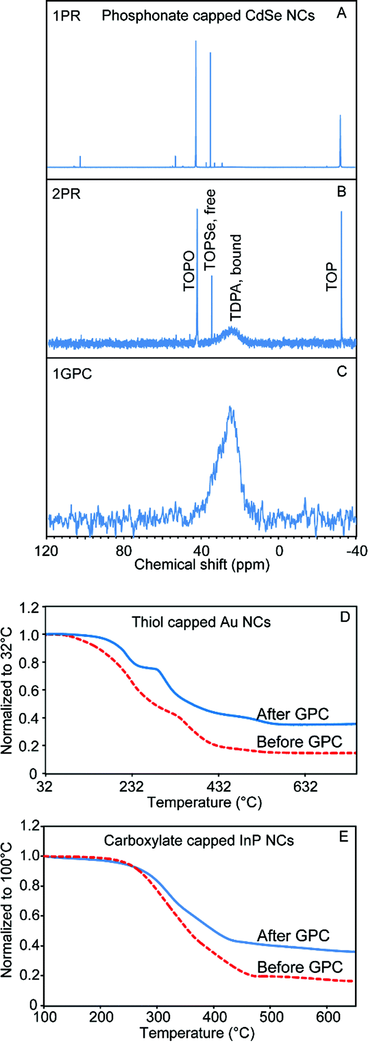 | ||
| Fig. 1 Purification of NCs with variety of composition and capping ligands. (A)–(C) 31P NMR of the TDPA-capped CdSe NCs purified by (A) one PR step, (B) two PR steps, and (C) one GPC purification. (D and E) TGA curves for the thiol-capped Au NCs (D) and carboxylate-capped InP NCs (E) before (dashed lines) and after (solid lines) the GPC purification. | ||
Besides carboxylates, alkylphosphonic acids (and their deprotonated forms) are among the most common ligands for oxide and compound semiconductor nanomaterials due to strong coordination of the surfaces of these materials.28,31 For example, the most common method to synthesize TDPA-capped CdSe QDs entails preparing a Cd phosphonate salt and mixing it with trioctylphosphine selenide (TOPSe) in a solvent consisting of trioctylphosphine (TOP) and trioctylphosphine oxide (TOPO).32 After NC growth, significant amounts of free phosphorus-containing molecules remain in the system; 31P NMR is ideal to profile the components remaining in the sample solution after purification by different methods. As shown in Fig. 1A–C, after one or two PR cycles, there was still a large amount of free TOPSe, TOP, and TOPO, while the only remaining phosphorus signal in the GPC purified sample is a broadened resonance that we associate with surface-bound phosphonate ligands.33 The absorption features of the CdSe QD sample were maintained after GPC purification, which confirms that QDs do not aggregate or etch inside the column (Fig. S1†).
Thiol-capped Au is representative of various metallic nanostructures.3 Here, Au NCs were prepared by a modified two phase liquid–liquid synthesis method designed by Mathias Brust and co-workers.34 TEM images revealed roughly spherical nanoparticles with a relatively broad size distribution ranging from 1 nm to 4 nm (Fig. S2†). Owing to the limitations of NMR for resolving the ligand atoms in this case, thermogravimetric analysis (TGA) was used to characterize the sample before and after the GPC purification. As shown in Fig. 1D, the purified sample displays a smaller mass loss compared to the sample before the purification, which indicates that a significant portion of the excess ligand content has been removed by GPC. The TGA curve for the GPC purified Au NCs clearly shows two separate stages of mass loss, which may indicate multiple binding modes among the residual strongly-bound ligands. This is different from the behavior of previously studied QD samples,18 in which mass loss associated with departure of neutral ligands was absent after GPC purification, and only a higher-temperature signal associated with breakdown of ionically-bound ligands remained.
InP QDs are a low-toxicity alternative to cadmium- and lead-based QD materials, which has stimulated intense interest in developing InP QDs for applications in bio-imaging, solid state lighting, and consumer display technologies.35–38 However, the nanocrystal growth and surface chemistry of InP QDs has proven more challenging to develop.37–40 Due to the air sensitivity of InP, QD samples are normally handled in an air- and moisture-free environment.35,41 PR purification is cumbersome to perform under air free conditions, considering the size of typical centrifuge instruments. For GPC purification of InP QDs, we found that we could pack a compact column inside of a N2-filled glovebox (Fig. S3†) and thus perform all of the purification processes within an N2 atmosphere. Fig. S3† also shows the absorption spectra of the InP QDs before and after GPC purification. There was not much change in the absorption features at the first exciton peak and the absorption in the UV range. However, we observed an increase in absorption at the second excitonic transition, which may be associated with a change of the ligand structure at the InP QD surface. As shown in Fig. 1E, after the GPC purification, a much smaller mass loss was observed by TGA. In order to quantify the removal of the ligand by GPC, quantitative NMR with ferrocene as the internal standard was used to measure the sample before and after the GPC purification (Fig. S4†). By integrating all the peaks that belong to InP QD surface ligands from the 1H NMR spectra, and comparing this value to the absorption spectra, we calculated that the H-to-QD ratio decreased 79% after the purification. Scanning TEM was also used to confirm the stability of the GPC-purified InP QD samples. As shown in Fig. S5,† individual InP QDs can be clearly observed by TEM, which confirms that GPC is not a destructive purification method for the InP QDs. Compared to CdSe QDs, InP QDs have weaker Z-contrast with the supporting carbon film. A pre-exposure of the sample with a defocused electron beam is normally required to prevent excess hydrocarbons from diffusing into the focused probe beam.42 However, we noticed that with the GPC-purified InP QD samples, in which a majority of ligands have been successfully removed, high quality images can be obtained with shorter pre-exposure time or even without this pre-treatment.
In order to test the feasibility of the GPC purification method on NCs with different shapes and sizes, we synthesized CdSe/CdS NCs with different aspect ratios. Spherical core/shell particles were made by the selective ionic adhesion and reaction (SILAR) method,32 and dot-in-rod structures with different aspect ratios were made by using a seeded growth method described by Carbone et al.43 In this method, the size and shape of the NCs can be tuned by changing the ligand population and the CdSe seed concentration during CdS deposition (representative spectra in Fig. S6†). TEM images are shown in Fig. 2A–D (from (A) to (D), samples were labelled as CdSe/CdS_NC_1 to CdSe/CdS_NC_4). The spherical particles were oleate-capped, while the nanorods were alkylphosphonate-capped.
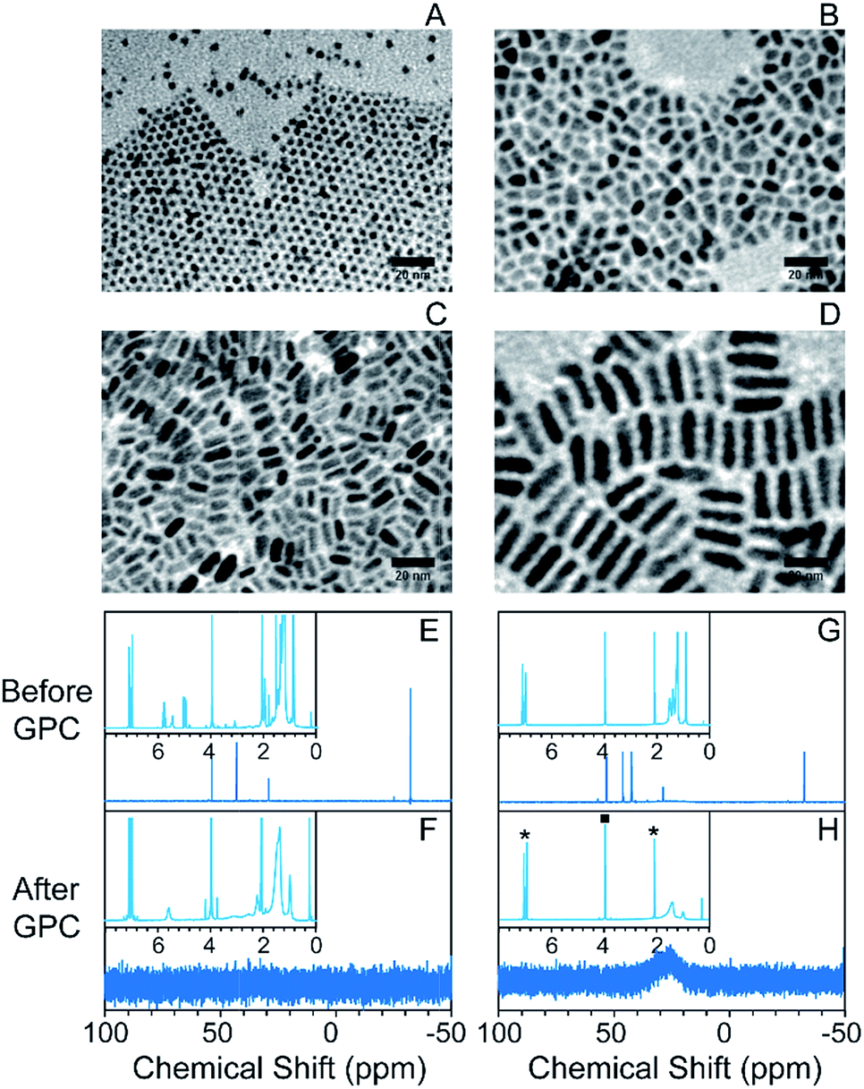 | ||
| Fig. 2 Purification of CdSe/CdS NCs with variety of morphologies. (A)–(D) TEM images of the NCs in different shapes ranging from spherical NCs to nanorods; from (A) to (D), samples were labelled as CdSe/CdS_NC_1 to CdSe/CdS_NC_4; (E–H) 31P NMR of the CdSe/CdS_NC_1 (E and F) and CdSe/CdS_NC_2 (G and H) before (E and G) and after (F and H) the GPC purification with 1H NMR spectra shown as the insets. Asterisks in (H) inset indicate peaks associated with the toluene solvent that are present in each sample. The square indicates the signal from the ferrocene internal standard. | ||
Following GPC purification in a toluene solvent, there is no change in the absorption spectra (Fig. S7† shows representative absorption spectra). Changes in the 1H and 31P NMR spectra after GPC purification, as shown in Fig. 2E–H and S8,† revealed highly effective separation of the NCs from small-molecule impurities and weakly bound ligands. In particular, for both the oleate-capped spherical NCs and the phosphonate-capped nanorods, the only remaining ligand signals are those associated with strongly bound ionic ligands. The impurities exited the column at an elution volume close to the total volume of the column (Fig. S9†). The GPC purification efficiency on the nanorods was also confirmed by TGA, where the mass loss only appeared at the ionic breakdown region and the total mass loss was sharply reduced after the GPC purification process (Fig. S10†).
Due to the greater surface to volume ratio and greater possible interaction area with neighboring particles, anisotropic particles can more readily aggregate than quasi-spherical ones and this could pose a risk of undesired aggregation when such particles are purified by PR, in which particles are necessarily brought into close proximity. The results here demonstrate that GPC is a viable alternative; the precision of the GPC purification method could be valuable in designing substoichiometric surface reactions to prepare anisotropically functionalized NCs.
In situ solvent change of nanocrystals on the GPC column
Colloidal NCs can in principle be brought from one solvent to another without removing them from solution via GPC, simply by eluting the NCs though a column that has been equilibrated with a solvent different from the one in which the NCs are loaded. This process is used in aqueous “desalting” columns to move biomolecules from one buffer to another. Because of the sensitivity of polymer gel volumes to solvent composition, it is prudent to confirm that a given solvent transition can be made without collapsing the gel or introducing flow irregularities. Fig. S11† illustrates the introduction of tetrahydrofuran (THF) to a polystyrene GPC column equilibrated with toluene. A visible contrast appears between polystyrene beads in toluene and the beads in THF, but the dividing line moves at a similar rate as the total flow velocity of the column, which suggests that diffusion between the two solvents should not influence the separation of macromolecules initially dissolved in the THF. Indeed, 1H NMR of the eluting solvents were measured and within 1 mL elution volume, the THF percentage in the solvent mixture rises from 3% to above 99%, which confirms that the diffusion rate is much slower than the flow rate.TDPA-capped CdSe NCs were used to test the ability to achieve a change of solvent for a NC solution using preparative GPC. As shown in Fig. 3, after eluting the unpurified CdSe NCs (initially dispersed in toluene) through a column equilibrated with THF, the NCs were well-purified and the solvent was completely switched to THF. We also eluted unpurified CdSe NCs in THF through a toluene GPC column and a similar result was obtained (Fig. S12†). This data confirms that solvent change of colloidal NCs can be achieved along with purification by GPC.
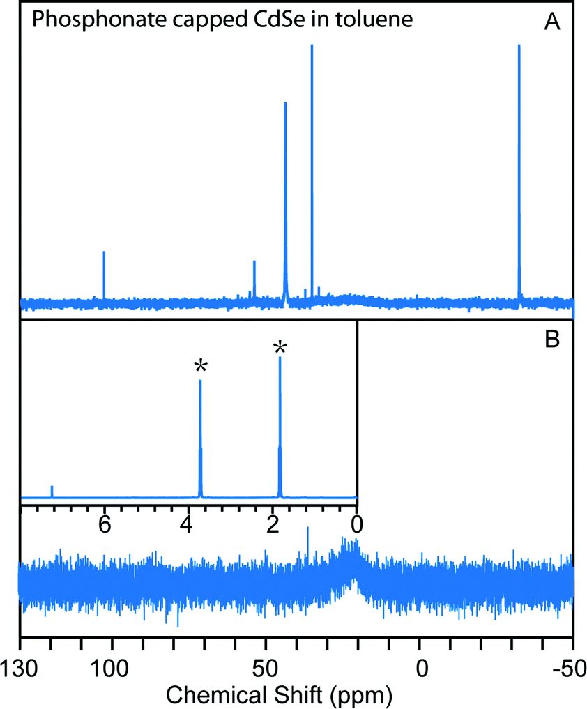 | ||
| Fig. 3 GPC in situ change of solvent with TDPA-capped CdSe NCs. (A) 31P NMR of the as-synthesized TDPA-capped CdSe NCs in toluene; (B) 31P NMR of the sample after traveling though the THF column revealing the purification of the NCs; the inset shows the 1H NMR of the solvent eluted out with the purified NCs in CDCl3, which confirms that the solvent has been changed from toluene to THF (asterisks). | ||
In situ ligand exchange of nanocrystals on the GPC column
In a ligand exchange reaction, a new ligand is introduced while the pre-existing ligand(s) are removed from the nanocrystal surface and appear as a product. We have previously observed that the highly effective purification achieved by GPC, which has the effect of removing excess pre-existing ligands, facilitates ligand exchange reactions carried out subsequently. In particular we have installed both small molecule (e.g. cysteine) and polymeric ligands to form water-soluble QDs.18,44Scheme 1 illustrates two approaches by which ligand exchange can be effected in situ on the GPC column by using the different flow rates of dissolved species to impose a controlled concentration of the new ligand while continuously removing pre-existing ligands as they dissociate from the nanocrystal surface. A flow chart illustrating the sequential steps during the GPC in situ ligand exchange is available in ESI (Fig. S13†). One or the other of the approaches will be appropriate depending on whether the new ligand exceeds the molecular weight cutoff for the size exclusion medium. In what follows, ligands that exceed the MWCO (and thus transit the column at a rate similar to the NCs) will be referred to as macromolecular ligands, while those that are significantly retained, passing at a rate similar to the solvent, will be referred to as small molecule ligands. Since GPC resins with different molecular weight exclusion ranges are available, this classification will depend on the choice of medium.
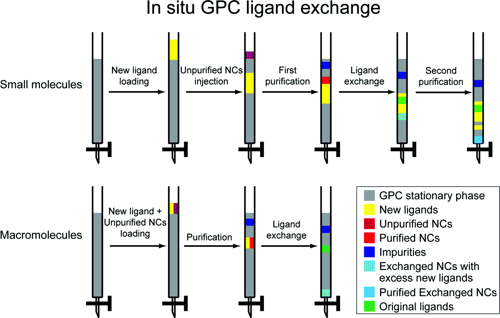 | ||
| Scheme 1 In situ GPC ligand exchange of colloidal nanocrystals. | ||
For the small molecule ligand exchange, the new ligands are placed onto the column prior to introducing the NCs, such that the NCs will overtake them. This is achieved by running a solution of the new ligand (totaling less than one column volume) onto the column, followed by a small portion of clean solvent. Then the unpurified NCs are introduced, and clean solvent is added to run them through the column. Three distinct processes occur in sequence as the NCs transit the column due to the differing elution rates. First, the NCs are purified as they transit the top region and are exposed to clean solvent; impurities and excess old ligands are retained. Secondly, the NCs encounter the new ligands and exchange takes place; as old ligands are released, they are continuously diluted and separated from the NCs. Thirdly, the exchanged sample moves beyond into clean solvent and is purified again; excess new ligands are left behind. In this way, we can achieve process intensification by combining two purification steps and the ligand exchange reaction into one sequence.
Since macromolecular ligands and NCs elute at a similar rate, a different approach is necessary. Both are loaded simultaneously onto a column that has been equilibrated with pure solvent. As they transit the column, impurities and old ligands are being continuously removed, while the macromolecule concentration remains roughly constant, allowing ligand exchange to proceed. The sample that is eluted from the column will contain excess macromolecules, but is otherwise purified. The excess macromolecular ligand can then be removed and recycled by a PR method or dialysis at a higher MWCO.
We first studied in situ ligand exchange with small molecules, starting with the exchange of oleate-capped CdSe QDs with octanethiol in toluene. Before we performed the exchange reaction, we first verified the flow characteristics of small molecules in the column. We used ferrocene as an easily-detected small molecule tracer and confirmed that its elution volume is close to one column volume and that its concentration is maintained (Fig. S14†) which suggests that it travels at the same rate as the solvent as was expected. We then used 1H NMR to confirm that octanethiol flows at the same rate as ferrocene. To accomplish this, a mixture of these two molecules was dissolved in 0.6 mL d8-toluene and injected into the GPC column packed with normal toluene (0.3 mL d8-toluene was used each time to rinse the column before and after the injection to minimize the influence of diffusion). The eluted sample was collected and 1H NMR was run directly to measure the ligand ratio. This method avoids the influence of evaporation on the volatile octanethiol when switching to deuterated solvent for the NMR measurement, and is possible due to the slow diffusion rate on the column. After GPC, the ratio between ferrocene and octanethiol changed less than 3%, which confirmed that octanethiol behaves similarly to the ferrocene tracer on the column. This knowledge allowed us to design the in situ ligand exchange experiment with confidence.
As described in the reaction scheme, ligand exchange was accomplished by pre-loading octanethiol onto the column, followed by running with a small amount of toluene and then injection of the oleate-capped CdSe. In order to better understand the in situ ligand exchange process, two control samples were prepared from the same stock solution for comparison; one consisted of GPC-purified CdSe NCs (no ligand exchange) and the other of octanethiol-exchanged CdSe NCs prepared by a more conventional sequential process (GPC purification, bench-top ligand exchange, and subsequent PR purification after ligand exchange). The same total mole ratio of the ligands to the NCs was used for both ligand exchange reactions. The 1H NMR spectrum of the first control sample shows that impurities present in the stock solution (Fig. 4A) are effectively separated from the QDs by GPC purification; the only remaining ligands on the surface after purification are the ionically bound oleates (Fig. 4B). A portion of this was used to prepare the second control sample by bench-top ligand exchange and subsequent purification by one PR cycle. As shown in Fig. 4C, the ligand exchange is close to completion, but there is still a broadened peak in the olefin region, which indicates that there are still some remaining oleate ligands interacting with the surface. When we performed the GPC in situ ligand exchange, starting with the stock solution (Fig. 4A), nearly complete exchange was observed as well (Fig. 4D). Both ligand exchanged samples exhibited a similar, small redshift in the absorption spectrum compared to the natively-capped QDs (Fig. S15†). These results confirmed that both the initial purification and the ligand exchange reaction indeed took place inside the column and that both experiments yielded similar products. However, the GPC exchanged sample only contained around one third of the remaining oleate species compared to the benchtop-exchanged samples (since both exchanges were close to complete, it is difficult to get an exact ligand-to-QD-ratio from quantitative NMR measurements). The total mole ratio of octanethiol![[thin space (1/6-em)]](https://www.rsc.org/images/entities/char_2009.gif) :QD was the same in each case, but the ligand was dissolved in 10× greater solvent volume for the GPC in situ exchange in order to achieve effective separation of the original ligands from the QDs during the period of overlap with the octanethiol band. As the octanethiol ligand concentration prepared within the GPC column was only 10% of that used in the bench-top reaction, this result suggests that the continuous separation of dissociated pre-existing ligands from the NCs as they transit the GPC column is responsible for the improved ligand exchange efficiency.
:QD was the same in each case, but the ligand was dissolved in 10× greater solvent volume for the GPC in situ exchange in order to achieve effective separation of the original ligands from the QDs during the period of overlap with the octanethiol band. As the octanethiol ligand concentration prepared within the GPC column was only 10% of that used in the bench-top reaction, this result suggests that the continuous separation of dissociated pre-existing ligands from the NCs as they transit the GPC column is responsible for the improved ligand exchange efficiency.
 | ||
| Fig. 4 GPC in situ ligand exchange of oleate-capped CdSe QDs with octanethiol. (A–D) 1H NMR analysis in toluene, focusing on olefin proton resonances. (A) Prior to ligand exchange. (B) After purification alone. (C) After benchtop ligand exchange performed subsequent to GPC. (D) After in situ ligand exchange as indicated. (E) TGA curves of the exchanged NCs prepared by different methods. | ||
An additional advantage of the GPC in situ exchange with small molecules is that, in a single run, it can remove excess new ligands once the exchange reaction is complete. Here, TGA was used to confirm the removal of excess octanethiol. Since the thiol exchange reactions were close to complete in both in situ and bench-top control experiments, the smaller mass loss from the in situ sample can be attributed to a smaller amount of excess new thiol ligand (Fig. 4E). While this demonstrates the multi-functional capabilities of the GPC process, excess ligands can sometimes be advantageous. Thiol-capped QDs are known to have poor stability towards oxidation, and frequently excess ligands are added to the exchange in part to slow down this process.30 As shown in Fig. S16,† after storing the GPC in situ exchanged sample and bench-top exchanged sample for 12 hours at 4 °C, the in situ sample started to precipitate while the benchtop exchanged sample remained stable in solution. This is further evidence that in the in situ GPC exchanged solution there is significantly less free thiol remaining. Purification and metrics such as these will allow the conditions necessary for storage of well-defined samples to be specified and created in a repeatable manner.
Another model small molecule ligand exchange reaction we studied is the pyridine ligand exchange of initially TDPA-capped CdSe NCs. Pyridine has been used to form a ligand shell of reduced thickness in a variety of NC applications.27 However, due to the weak binding strength between pyridine and the NC surface, the ligand exchange is normally far from complete and multiple treatments are frequently required.45 Thus, whereas the oleate-to-thiol exchange is a useful proof of principle showing that surface reactions can be accomplished on the GPC column, the exchange of phosphonates for pyridine is a better test of the ability of in situ GPC ligand exchange to increase the efficiency of a difficult transformation. Here, the in situ exchange was achieved by loading the stock TDPA-QD solution in pyridine onto a GPC column equilibrated with pyridine as the mobile phase. We could in principle start with toluene as the solvent and combine purification, solvent change and ligand exchange all together; however, in some cases, some impurities precipitated when the toluene and pyridine came in contact. As shown in Fig. S17,† after the ligand exchange process, similar to the bench-top experiment, the sample spectrum blue shifted indicating that the surface Cd(TDPA)2 was replaced by the pyridine.45 The 31P NMR spectra confirmed the displacement, where a much weaker signal, compared to purification only in the toluene column, was observed after the in situ pyridine GPC ligand exchange (Fig. S18†). In order to quantify the displacement of phosphonate ligands by pyridine, SEM/EDX was used to characterize the phosphorus-to-cadmium ratios in films of in situ GPC exchanged CdSe QDs, as well as toluene GPC-purified QDs and benchtop-exchanged controls. Among these three samples, the toluene GPC-purified sample showed the highest P:Cd ratio (1.67); for the benchtop exchange followed by one PR cycle, the ratio dropped to 0.66; for the in situ exchange on the GPC column, the ratio decreased to 0.14. This result confirms that the separation of the pre-existing ligand product that is achieved during ligand exchange on the GPC column can effectively improve the efficiency of the ligand exchange reaction.
To explore on-column ligand exchange with macromolecular ligands, we selected the exchange of the oleate-capped CdSe/CdZnS core/shell QDs with methacrylate-based polymeric imidazole ligands (MA-PILs).44 This ligand system is representative of a growing family of hydrophilic, multiply-binding polymers that has emerged as an effective route to biocompatible QDs with high colloidal stability.26,46–49 The ligand selected contains approximately equal numbers of poly(ethylene glycol) and imidazole side-chains and has a total molecular weight ∼27 kD. When this ligand exchange is conducted on the benchtop in chloroform solvent, we have shown it to provide water-soluble QDs with long term stability and high brightness.44,48 In the case of performing NC ligand exchange with macromolecules, the elution rates of the NCs and macromolecular ligand are essentially the same. Therefore, excess unbound polymers will not be separated from the NCs by elution on the GPC medium used here; but effective removal of the old ligands can be achieved throughout the chromatography without diluting the total macromolecule concentration, which should promote the ligand exchange reaction at the nanocrystal surface. We conducted the reaction by loading a mixture of the unpurified stock solution QDs and MA-PIL ligands simultaneously onto a column that had been equilibrated with chloroform as the mobile phase. Due to the high density and low viscosity of chloroform, a high flow rate was achieved under gravity and the QDs eluted after ∼10 minutes. As shown in Fig. 5, 1H NMR revealed both the impurities and the original ligands can be removed completely from the sample. As shown in Fig. S19,† the absorption features were maintained before and after the in situ exchange. The quantum yield of the MA-PIL capped QDs in chloroform is around 39% after the exchange (relative QY measurement with Rhodamine 590 in ethanol as the reference). The sample could then be precipitated with hexane and redispersed in water, after which it maintains its colloidal stability and its optical features, though a decrease in brightness is observed (Fig. S20†).
 | ||
| Fig. 5 GPC in situ ligand exchange with MA-PIL macromolecular ligand monitored by 1H NMR. (A) Spectrum of the pure MA-PIL polymer. (B) Spectrum of the oleate-capped CdSe/CdZnS NCs stock solution. (C) In situ exchanged MA-PIL-capped CdSe/CdZnS NCs. Insets expand the olefin resonance region to confirm the completeness of the exchange reaction. | ||
Conclusions
The results shown above attest that GPC can serve as a general technique for separation of colloidal nanoparticles from small molecules in anhydrous solvents without requiring precipitation, and also as a means for conducting ligand exchange chemistry with controlled concentrations and interaction time. We have previously employed GPC purification to demonstrate reversible changes in QY upon the removal and re-introduction of neutral ligands from the surface of natively-capped CdSe/CdS and CdSe/CdxZn1−xS QDs.19 We have now demonstrated that these steps can be accomplished in an air-free environment so as to handle highly sensitive samples. Purification and ligand exchange steps can be strung together to accomplish multiple functions in a single run and in a highly repeatable fashion. These characteristics could allow GPC techniques for manipulating nanocrystals to be adapted to compact industrial flow reactors for rapid discovery, prototyping and optimization of nanocrystal surface reactions. In this study, we have taken advantage of the continuous removal of native ligands as the QDs transit the column to help drive ligand exchange with small molecules and macromolecular ligands. In colloidal nanocrystal systems in which ligands are subject to dynamic exchange with the solution, GPC can serve as a means to explore the behavior of weakly bound ligands during separations and their influence on properties, as well as the behavior of strongly bound ligands in exchange reactions. There remains a vast range of possibilities that should be explored in future studies. For example, intermediate states during the GPC in situ ligand exchange could be “trapped” by effective separation of NCs from the new small molecule ligands. It may be then be possible to consider limits on associative and dissociative ligand exchange mechanisms through kinetics experiments enabled by control of the nanocrystal and ligand concentrations and the GPC flow rate.Acknowledgements
This research was supported by the University of South Carolina, including a SPARC Graduate Research Fellowship and Dean's Dissertation Fellowship to Y. S., and a SPARC Graduate Research Fellowship to M. Y. G. An NSF IGERT fellowship supports A. R. under award #1250052. Additional support was provided through South Carolina EPSCOR grant #EPS-0903795 to A. B. G. (a sub-award from NSF grant #1317771). B. M. C. thanks the University of Washington and the Alfred P. Sloan Foundation for support of this work.Notes and references
- M. V. Kovalenko, L. Manna, A. Cabot, Z. Hens, D. V. Talapin, C. R. Kagan, V. I. Klimov, A. L. Rogach, P. Reiss, D. J. Milliron, P. Guyot-Sionnnest, G. Konstantatos, W. J. Parak, T. Hyeon, B. A. Korgel, C. B. Murray and W. Heiss, ACS Nano, 2015, 9, 1012–1057 CrossRef CAS PubMed.
- M. Liu and P. Guyot-Sionnest, J. Phys. Chem. B, 2005, 109, 22192–22200 CrossRef CAS PubMed.
- P. D. Jadzinsky, G. Calero, C. J. Ackerson, D. A. Bushnell and R. D. Kornberg, Science, 2007, 318, 430–433 CrossRef CAS PubMed.
- X. Ye, L. Jin, H. Caglayan, J. Chen, G. Xing, C. Zheng, V. Doan-Nguyen, Y. Kang, N. Engheta, C. R. Kagan and C. B. Murray, ACS Nano, 2012, 6, 2804–2817 CrossRef CAS PubMed.
- Q. Zhang, L. Han, H. Jing, D. A. Blom, Y. Lin, H. L. Xin and H. Wang, ACS Nano, 2016, 10, 2960–2974 CrossRef CAS PubMed.
- A. J. Morris-Cohen, M. Malicki, M. D. Peterson, J. W. J. Slavin and E. A. Weiss, Chem. Mater., 2013, 25, 1155–1165 CrossRef CAS.
- J. Vela, J. Phys. Chem. Lett., 2013, 4, 653–668 CrossRef CAS PubMed.
- S. J. Oh, N. E. Berry, J.-H. Choi, E. A. Gaulding, H. Lin, T. Paik, B. T. Diroll, S. Muramoto, C. B. Murray and C. R. Kagan, Nano Lett., 2014, 14, 1559–1566 CrossRef CAS PubMed.
- J. Owen, Science, 2015, 347, 615–616 CrossRef CAS PubMed.
- N. Zhan, G. Palui, J.-P. Merkl and H. Mattoussi, J. Am. Chem. Soc., 2016, 138, 3190–3201 CrossRef CAS PubMed.
- R. Tan, D. A. Blom, S. Ma and A. B. Greytak, Chem. Mater., 2013, 25, 3724–3736 CrossRef CAS.
- R. Tan, Y. Shen, S. K. Roberts, M. Y. Gee, D. A. Blom and A. B. Greytak, Chem. Mater., 2015, 27, 7468–7480 CrossRef CAS.
- O. Levenspiel, Chemical Reaction Engineering, Wiley, 3rd edn, 1998 Search PubMed.
- T. Van Gerven and A. Stankiewicz, Ind. Eng. Chem. Res., 2009, 48, 2465–2474 CrossRef CAS.
- B. K. H. Yen, N. E. Stott, K. F. Jensen and M. G. Bawendi, Adv. Mater., 2003, 15, 1858–1862 CrossRef CAS.
- M. Abolhasani, C. W. Coley, L. Xie, O. Chen, M. G. Bawendi and K. F. Jensen, Chem. Mater., 2015, 27, 6131–6138 CrossRef CAS.
- I. Lignos, S. Stavrakis, G. Nedelcu, L. Protesescu, A. J. deMello and M. V. Kovalenko, Nano Lett., 2016, 16, 1869–1877 CrossRef CAS PubMed.
- Y. Shen, M. Y. Gee, R. Tan, P. J. Pellechia and A. B. Greytak, Chem. Mater., 2013, 25, 2838–2848 CrossRef CAS.
- Y. Shen, R. Tan, M. Y. Gee and A. B. Greytak, ACS Nano, 2015, 9, 3345–3359 CrossRef CAS PubMed.
- T. X. Ding, J. H. Olshansky, S. R. Leone and A. P. Alivisatos, J. Am. Chem. Soc., 2015, 137, 2021–2029 CrossRef CAS PubMed.
- K. Davis, B. Qi, M. Witmer, C. L. Kitchens, B. A. Powell and O. T. Mefford, Langmuir, 2014, 30, 10918–10925 CrossRef CAS PubMed.
- L. Ye, T. Pearson, C. Dolbashian, P. Pstrak, A. R. Mohtasebzadeh, B. Fellows, O. T. Mefford and T. M. Crawford, Adv. Funct. Mater., 2016 DOI:10.1002/adfm.201504749.
- B. S. Flavel, K. E. Moore, M. Pfohl, M. M. Kappes and F. Hennrich, ACS Nano, 2014, 8, 1817–1826 CrossRef CAS PubMed.
- R. M. Jain, M. Ben-Naim, M. P. Landry and M. S. Strano, J. Phys. Chem. C, 2015, 119, 22737–22745 CAS.
- W. Wang, A. Kapur, X. Ji, M. Safi, G. Palui, V. Palomo, P. E. Dawson and H. Mattoussi, J. Am. Chem. Soc., 2015, 137, 5438–5451 CrossRef CAS PubMed.
- W. Wang, X. Ji, A. Kapur, C. Zhang and H. Mattoussi, J. Am. Chem. Soc., 2015, 137, 14158–14172 CrossRef CAS PubMed.
- G. H. Carey, A. L. Abdelhady, Z. Ning, S. M. Thon, O. M. Bakr and E. H. Sargent, Chem. Rev., 2015, 115, 12732–12763 CrossRef CAS PubMed.
- R. Gomes, A. Hassinen, A. Szczygiel, Q. Zhao, A. Vantomme, J. C. Martins and Z. Hens, J. Phys. Chem. Lett., 2011, 2, 145–152 CrossRef CAS.
- G. Palui, T. Avellini, N. Zhan, F. Pan, D. Gray, I. Alabugin and H. Mattoussi, J. Am. Chem. Soc., 2012, 134, 16370–16378 CrossRef CAS PubMed.
- W. Liu, H. S. Choi, J. P. Zimmer, E. Tanaka, J. V. Frangioni and M. Bawendi, J. Am. Chem. Soc., 2007, 129, 14530–14531 CrossRef CAS PubMed.
- L. Li, J. Lv, Y. Shen, X. Guo, L. Peng, Z. Xie and W. Ding, ACS Catal., 2014, 4, 2746–2752 CrossRef CAS.
- A. B. Greytak, P. M. Allen, W. Liu, J. Zhao, E. R. Young, Z. Popović, B. J. Walker, D. G. Nocera and M. G. Bawendi, Chem. Sci., 2012, 3, 2028–2034 RSC.
- Z. Hens and J. C. Martins, Chem. Mater., 2013, 25, 1211–1221 CrossRef CAS.
- M. Brust, M. Walker, D. Bethell, D. J. Schiffrin and R. Whyman, J. Chem. Soc. Chem. Commun., 1994, 801–802 RSC.
- L. Xie, D. K. Harris, M. G. Bawendi and K. F. Jensen, Chem. Mater., 2015, 27, 5058–5063 CrossRef CAS.
- K. Kim, D. Yoo, H. Choi, S. Tamang, J.-H. Ko, S. Kim, Y.-H. Kim and S. Jeong, Angew. Chem., Int. Ed., 2016, 55, 3714–3718 CrossRef CAS PubMed.
- D. C. Gary, M. W. Terban, S. J. L. Billinge and B. M. Cossairt, Chem. Mater., 2015, 27, 1432–1441 CrossRef CAS.
- D. Franke, D. K. Harris, L. Xie, K. F. Jensen and M. G. Bawendi, Angew. Chem., Int. Ed., 2015, 54, 14299–14303 CrossRef CAS PubMed.
- A. Cros-Gagneux, F. Delpech, C. Nayral, A. Cornejo, Y. Coppel and B. Chaudret, J. Am. Chem. Soc., 2010, 132, 18147–18157 CrossRef CAS PubMed.
- D. C. Gary and B. M. Cossairt, Chem. Mater., 2013, 25, 2463–2469 CrossRef CAS.
- K. Kim, D. Yoo, H. Choi, S. Tamang, J.-H. Ko, S. Kim, Y.-H. Kim and S. Jeong, Angew. Chem., Int. Ed., 2016, 55, 3714–3718 CrossRef CAS PubMed.
- R. F. Egerton, P. Li and M. Malac, Micron, 2004, 35, 399–409 CrossRef CAS PubMed.
- L. Carbone, C. Nobile, M. De Giorgi, F. D. Sala, G. Morello, P. Pompa, M. Hytch, E. Snoeck, A. Fiore, I. R. Franchini, M. Nadasan, A. F. Silvestre, L. Chiodo, S. Kudera, R. Cingolani, R. Krahne and L. Manna, Nano Lett., 2007, 7, 2942–2950 CrossRef CAS PubMed.
- A. Viswanath, Y. Shen, A. N. Green, R. Tan, A. B. Greytak and B. C. Benicewicz, Macromolecules, 2014, 47, 8137–8144 CrossRef CAS.
- I. Lokteva, N. Radychev, F. Witt, H. Borchert, J. Parisi and J. Kolny-Olesiak, J. Phys. Chem. C, 2010, 114, 12784–12791 CAS.
- W. Liu, A. B. Greytak, J. Lee, C. R. Wong, J. Park, L. F. Marshall, W. Jiang, P. N. Curtin, A. Y. Ting, D. G. Nocera, D. Fukumura, R. K. Jain and M. G. Bawendi, J. Am. Chem. Soc., 2010, 132, 472–483 CrossRef CAS PubMed.
- P. Zhang, S. Liu, D. Gao, D. Hu, P. Gong, Z. Sheng, J. Deng, Y. Ma and L. Cai, J. Am. Chem. Soc., 2012, 134, 8388–8391 CrossRef CAS PubMed.
- C. M. Johnson, K. M. Pate, Y. Shen, A. Viswanath, R. Tan, B. C. Benicewicz, M. A. Moss and A. B. Greytak, J. Colloid Interface Sci., 2015, 458, 310–314 CrossRef CAS PubMed.
- X. Zhao, Y. Shen, E. A. Adogla, A. Viswanath, R. Tan, B. C. Benicewicz, A. B. Greytak, Y. Lin and Q. Wang, J. Mater. Chem. B, 2016, 4, 2421–2427 RSC.
Footnote |
| † Electronic supplementary information (ESI) available: Experimental materials and methods, Fig. S1–S20. See DOI: 10.1039/c6sc01301e |
| This journal is © The Royal Society of Chemistry 2016 |