
 Open Access Article
 This Open Access Article is licensed under a
 Creative Commons Attribution 3.0 Unported Licence
Structural changes correlated with magnetic spin state isomorphism in the S2 state of the Mn4CaO5 cluster in the oxygen-evolving complex of photosystem II†
Ruchira
Chatterjee‡
a,
Guangye
Han‡§
a,
Jan
Kern
ab,
Sheraz
Gul
a,
Franklin D.
Fuller
a,
Anna
Garachtchenko
a,
Iris D.
Young
a,
Tsu-Chien
Weng
c,
Dennis
Nordlund
d,
Roberto
Alonso-Mori
b,
Uwe
Bergmann
e,
Dimosthenis
Sokaras
d,
Makoto
Hatakeyama
f,
Vittal K.
Yachandra
*a and
Junko
Yano
*a
aMolecular Biophysics and Integrated Bioimaging Division, Lawrence Berkeley National Laboratory, MS 66-0200, 1 Cyclotron Rd., Berkeley, CA 94720-8099, USA. E-mail: JYano@lbl.gov; vkyachandra@lbl.gov; Tel: +1 510 486 4366 Tel: +1 510 486 4963
bLCLS, SLAC National Accelerator Laboratory, Menlo Park, CA, USA
cCenter for High Pressure Science &Technology Advanced Research, Shanghai, China
dSSRL, SLAC National Accelerator Laboratory, Menlo Park, CA, USA
ePULSE, SLAC National Accelerator Laboratory, Menlo Park, CA, USA
fRIKEN, Research Cluster for Innovation, Wako, Saitama, Japan
First published on 9th May 2016
Abstract
The Mn4CaO5 cluster in photosystem II catalyzes the four-electron redox reaction of water oxidation in natural photosynthesis. This catalytic reaction cycles through four intermediate states (Si, i = 0 to 4), involving changes in the redox state of the four Mn atoms in the cluster. Recent studies suggest the presence and importance of isomorphous structures within the same redox/intermediate S-state. It is highly likely that geometric and electronic structural flexibility play a role in the catalytic mechanism. Among the catalytic intermediates that have been identified experimentally thus far, there is clear evidence of such isomorphism in the S2 state, with a high-spin (5/2) (HS) and a low spin (1/2) (LS) form, identified and characterized by their distinct electron paramagnetic resonance (EPR spectroscopy) signals. We studied these two S2 isomers with Mn extended X-ray absorption fine structure (EXAFS) and absorption and emission spectroscopy (XANES/XES) to characterize the structural and electronic structural properties. The geometric and electronic structure of the HS and LS S2 states are different as determined using Mn EXAFS and XANES/XES, respectively. The Mn K-edge XANES and XES for the HS form are different from the LS and indicate a slightly lower positive charge on the Mn atoms compared to the LS form. Based on the EXAFS results which are clearly different, we propose possible structural differences between the two spin states. Such structural and magnetic redox-isomers if present at room temperature, will likely play a role in the mechanism for water-exchange/oxidation in photosynthesis.
Introduction
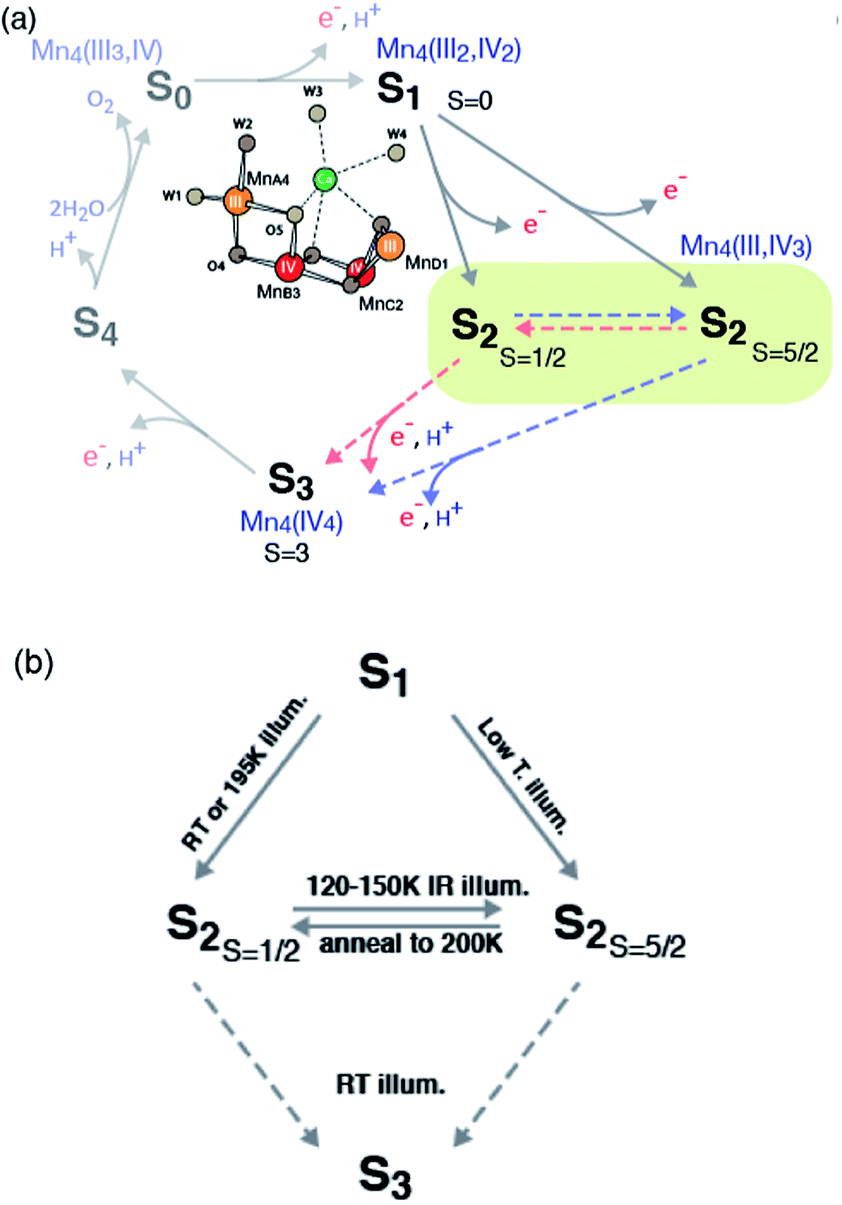
In oxygenic photosynthesis, light-driven water oxidation to molecular oxygen is carried out by the oxygen-evolving complex (OEC) in photosystem II (PSII). PSII is a multisubunit protein complex in the thylakoid membrane of plants, algae, and cyanobacteria.1,2 The OEC consists of four oxo-bridged Mn atoms and one Ca atom (Mn4CaO5) ligated to the D1 and CP43 subunits by carboxylate and histidine ligands.3,4 During water oxidation, the Mn4CaO5 complex cycles through five intermediate states, collectively called the S states, labeled S0–S4 in the Kok cycle.5 S0 is the most reduced state while S1, S2 and S3 represent sequentially higher oxidation states in the OEC. O2 is released during the S3 → [S4] → S0 transition, where S4 is a transient state. Thus, the Mn4CaO5 cluster accumulates four charges before the release of O2.The oxidation state of each S-state has been formally assigned as MnIII3MnIV for S0, MnIII2MnIV2 for S1, MnIIIMnIV3 for S2, and MnIV4 for S3.6–10 We note that there has been debate regarding the oxidation state assignment of the S3 state (i.e. whether it is formally MnIV4 or MnIIIMnIV3 with charge delocalized on the ligands),8,11,12 and the current view from several experiments point more towards the formal oxidation state of MnIV4. However, formal oxidation states does not necessarily coincide with effective number of electrons in the metal valence shells because of important factors like metal–ligand covalency.13,14 A recent resonant inelastic X-ray scattering spectroscopy (RIXS) study indicate increasing delocalization of positive charge on to the ligands during the S-state transitions.15 Among the S-states, the S2 state is the most studied state due to the presence of rich EPR signals and nearly 100% conversion by illumination starting from the dark stable S1 state. The subsequent S2 to S3 state transition is accompanied by noticeable Mn–Mn distance changes,16 and several factors such as Ca-depletion,17 site-specific mutations,18 and chemical treatments (for example, with fluoride)19 are known to block this advance. The requirement for a structural change, and its susceptibility to many chemical and biochemical treatments, makes S2 to S3 transition one of the critical steps for water oxidation reaction during the S-state cycle.
In recent studies,20–24 the isomorphism observed in the S2 state has been suggested to be of importance in relation to the formation of the S3 state, where the chemical environment is prepared for the O–O bond formation to occur in the following steps. The presence of such chemical flexibility within the same OEC redox state (i.e. S-state) may play an important role in the catalytic process, for example, by providing a low energy barrier for the water exchange process. In the current study, we investigate isomorphism in the S2 state using Mn K-edge X-ray absorption, both XANES and EXAFS, and emission spectroscopy, and further discuss the mechanistic implication of such isomorphous states to the catalytic function of the OEC.
In the S2 state, two types of EPR signals have been assigned to the Mn cluster. The multiline signal (MLS) centered at g = 2 (S2-g2), exhibiting at least 18 partially resolved hyperfine lines at X-band (∼9 GHz), is a low spin (Stotal = 1/2, i.e. MnIII/MnIV and MnIV/MnIV are antiferromagnetically-coupled, respectively) ground state.9,25–33 Another broad featureless EPR signal at g ≥ 4.1 (S2-g4), attributed to a higher spin multiplicity (Stotal = 5/2, i.e. ferromagnetically-coupled three MnIV with antiferromagnetically-coupled one MnIII) ground state, is also observed under different experimental conditions.34–40
The high spin (Stotal = 5/2, called HS S2 or S2-g4 in the text) and low spin (Stotal = 1/2, called LS S2 or S2-g2 in the text) forms in the S2 state are interrelated, on the basis of the observation of amplitude conversion of the S2-g4 EPR signal to the S2-g2 EPR signal.34,41–43 The distribution of high spin and low spin species, g values and hyperfine coupling values of these spin state changes are sensitive to several parameters, such as (a) species (higher-plant, thermophile or non-thermophile cyanobacterial PSII), (b) the presence of chemical additives like alcohol (methanol or ethanol), sucrose and glycerol (often used as a cryo-protectant) in the sample, (c) substitution of the native Ca2+ in the OEC (Ca2+-PSII) by Sr (Sr2+-PSII), and (d) halide substitution in PSII with Br− or I− replacing the Cl− of the native state. A detailed discussion of these studies can be found in several reviews.32,44,45 Briefly, in samples illuminated at 195 K, both S2-g2 and S2-g4 signals are observed in the presence of sucrose, while with glycerol, ethylene glycol, or ethanol, the MLS is enhanced and the S2-g4 EPR signal is suppressed.41 Some treatments such as (c) and (d) stabilize the HS S2 form in the presence of the LS S2 form. Illumination by near-infrared (NIR) light at low temperature (∼150 K) has been shown to convert the S2-g2 form to the S2-g4 form without further advancement of S-state of the OEC.39,41 Subsequent annealing in the dark at 200 K converts the S2-g4 form back to the S2-g2 form,34 showing that these two forms are interconvertible. Both S2-g2 and S2-g4 forms show similar oscillation patterns around the S state cycle.41 PSII samples treated with NH3, F−, NO3−, or I− or when Ca2+ is replaced by Sr2+ have been reported to show an enhanced S2-g4 signal with the line widths and g values being slightly different.46 The S-state transitions focused on the S1–S2–S3 steps are summarized in Scheme 1.
 | ||
| Scheme 1 Formation of the S2-g2 and S2-g4 states in PSII from plants and the conversion between these two states. | ||
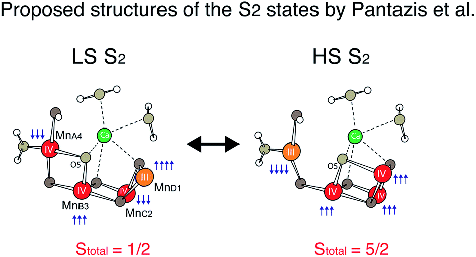
Recently, density functional theory (DFT) calculations by two groups suggest theoretical structural models corresponding to the two spin states21,47 and conclude that the two spin states are almost isoenergetic. Ab initio molecular dynamics simulations by Bovi et al. showed that these two states could interconvert over a low barrier (ΔG# of 10.6 kcal mol−1).48 In proposed models by Pantazis et al.,21 the two spin states arise from a different location of MnIII; for LS S2, MnIII is located in the corner of the cubane motif (MnD1), while for HS S2, it is located at the tail MnA4 (see Scheme 1). They along with a few other studies suggest that such isomorphism makes O5 unique, and that O5 may be a likely candidate for the slow-exchanging water in the S2 state.3,4,22,49–54
Previously, Liang et al. performed an XAS study on the HS S2 state.55 In their study, the authors concluded that HS S2 state is different from S1 and LS S2. They observe that the low spin S2 state showed a positive K edge shift compared to high spin state and an elongation of one of the Mn–Mn bond distances from 2.73 to 2.85 Å.55 In our current study, with improved data quality and the structural information available for the OEC S1 state from X-ray diffraction,4 we gain a detailed structural insight that will help us in understanding the mechanistic detail of the S2 to S3 transition.
In this study, we used X-ray absorption (XAS) and X-ray emission spectroscopy (XES) to study the nature of the two spin states in the S2 state. The possible structural changes are analysed based on the geometry obtained from the 1.95 Å resolution crystal structure of the S1 state.4 We discuss the structural and electronic structural differences of the two spin states, and its relation to the functional role in S2 to S3 transition and subsequently during the water oxidation reaction.
Materials and method
Preparation of PSII membranes
PSII-enriched membrane fragments were prepared under dim green light from spinach leaves according to Berthold et al.56 PSII membranes were resuspended to a chlorophyll (Chl) concentration of 8 mg Chl per mL in a buffer containing 30% (v/v) glycerol, 50 mM MES–NaOH (pH 6.0), 5 mM MgCl2, 5 mM CaCl2, 15 mM NaCl and stored at −80 °C until used. All samples were measured in this buffer. Oxygen-evolution activity of 400–500 μmol of O2 per mg of Chl per h was observed. The oxygen-evolution activity was measured in a buffer with 50 mM MES–NaOH (pH 6.0), 10 mM MgCl2, 5 mM CaCl2 and 15 mM NaCl at 25 °C under saturating light and in the presence of 0.5 mM phenyl-p-benzoquinone (pPBQ) as electron acceptor.The samples for X-ray studies were prepared by mounting PSII membranes pellets (chlorophyll concentrations in these samples ranged from 20 to 25 mg mL−1) directly onto the Lucite sample holders, with a hollowed compartment (dimensions of 2.1 × 0.3 × 0.15 cm) backed by a piece of mylar tape. All illuminations, EPR, and X-ray measurements were performed directly on samples mounted in these holders.
Generation of the S-states by illumination
All the sample preparations as described above were performed in the dark or with dim green light at 4 °C to poise the PSII centers in the S1 state and then the samples were frozen in liquid nitrogen. The HS S2 and LS S2 states were generated by light illumination at 140 ± 1 K or 195 K. Prior to illumination, dark-adapted samples were equilibrated for 3 min at 140 ± 1 K or 195 K. For 195 K illumination, the temperature was maintained in a dry ice/ethanol bath in an unsilvered dewar, and samples were continuously illuminated for 10 min using a 400 W tungsten lamp, with a 7 cm path of 5% CuSO4 as a heat and IR light filter. For 140 K illumination, the temperature was maintained with a continuous stream of liquid nitrogen-cooled nitrogen gas. Samples were continuously illuminated for 10 min using a 400 W tungsten lamp, with a 7 cm path of water as a heat filter. The temperature was monitored throughout the illumination period with a copper–constantan thermocouple. After illumination, samples were frozen in liquid nitrogen within 1–2 seconds. The 2 flash data used in this study was collected previously. The S3 spectra were deconvoluted using the protocol established previously.57EPR spectroscopy
Low-temperature X-band EPR spectra were recorded using a Varian E109 EPR spectrometer equipped with a Model 102 Microwave bridge. Sample temperature was maintained at 8 K using an Air Products LTR liquid helium cryostat. The following spectrometer conditions were used: microwave frequency, 9.22 GHz; field modulation amplitude, 32 G at 100 kHz; microwave power, 20 mW. The EPR signals were quantitated by adding the peak-to-trough amplitudes of S2-g4 or four of the downfield hyperfine lines of the S2-g2 MLS, respectively.XAS measurements
X-ray absorption spectra were collected at the Stanford Synchrotron Radiation Lightsource (SSRL) on beamline 7-3 at an electron energy of 3.0 GeV and an average current of 500 mA. The intensity of the incident X-rays was monitored by a N2-filled ion chamber (I0) in front of the sample. The slit in front of the I0 detector was closed to a vertical size of 2.5 mm and a horizontal size of 14 mm. The radiation was monochromatized by a Si (220) double-crystal monochromator. The total photon flux on the sample was limited to ∼3 × 10⁶ photons per μm2, which was determined to be non-damaging on the basis of detailed radiation-damage studies.16,58–60 We compared consecutive XAS scans from each sample and detected no shift in the K-edge energy over first five scans at each spot (Fig. S1†). The samples were protected from the beam during the monochromator movements between different energy positions by a shutter that was synchronized with the scan program. The samples were kept at 8 K in a He atmosphere at ambient pressure by using an Oxford CF-1208 continuous-flow liquid He cryostat. Data were recorded as fluorescence excitation spectra by using a germanium 30-element energy-resolving detector (Canberra Electronics). For Mn XAS, energy was calibrated by the pre-edge peak of KMnO4 (6543.3 eV), which was placed between two N2-filled ionization chambers (I1 and I2) after the sample.Data reduction of the EXAFS spectra was performed using SIXPAK.61 Pre-edge and post-edge backgrounds were subtracted from the XAS spectra, and the results were normalized with respect to edge height. Background removal in k-space was achieved through a five-domain cubic spline. Curve fitting was performed with Artemis and IFEFFIT software using ab initio-calculated phases and amplitudes from the program FEFF 8.2.62,63 EXAFS curve-fitting procedure is described in detail in the ESI.† Mn XANES pre-edge spectra were fit using EDG_FIT in EXAFSPAK.64 The XANES inflection point energy (IPE) was extracted from zero crossing of the second derivative in the energy region between 6550 eV and 6554 eV.
XES measurements
X-ray emission spectra were collected at SSRL on beamline 6-2. The beamline monochromator, using two cryogenically cooled Si crystals in (111) reflection, was used to set the incident photon energy to 10.4 keV. The X-ray beam was focused to 0.45 (V) × 0.45 (H) mm (fwhm) by means of vertical and horizontal focusing mirrors. The X-ray flux at 10.4 keV was ∼1 × 10¹³ photons per s per mm2. During the measurement, samples were kept at 10 K in a continuous flow liquid helium cryostat (Oxford Instruments CF1208) under helium exchange gas atmosphere. Emission spectra were recorded by means of a high-resolution crystal-array spectrometer, using the 440 reflection of 7 spherically bent Si(110) crystals (100 mm diameter, 1 m radius of curvature), aligned on intersecting Rowland circles.65 An energy-resolving Si drift detector (Vortex) was positioned at the focus of the 7 diffracting elements. A helium-filled polyethylene bag was placed between the cryostat and the spectrometer to minimize signal attenuation due to air absorption. Each energy point in the spectra was collected at a fresh sample spot. The maximum exposure time at each spot was 2.5 seconds and the signal was read out in bins of 50 ms duration. At first, a time-scan at a single emission energy was carried out for each S-state to check the onset time of radiation-induced changes of the signal intensity. No changes were observed at least for the first 1.5 s, and therefore the first 20 bins (equivalent to 1 s) were averaged for the final spectra. The signal intensity from each sample spot was normalized by the emission signal intensity recorded at 6491.5 eV within 7 s from the same sample spot, after going through all the fresh spots. Fig. S2† shows the XES spectra after first 20 bins (equivalent to 1 s) and from bin 11–30 (0.5–1.5 s) of the 140 K NIR illuminated sample. We see no damage till 1.5 s of data collection.Computational details
The optimizations were carried out using Gaussian 09 (ref. 66) and ONIOM calculation.67 The initial structure was based on a previous study on the OEC in the S2 state.68S = 13/2 spin state was used so that the oxidation states of Mn ions in the S2 state is MnIIIMnIV3. The Mn oxidation states were determined by the Mulliken's spin population analysis. The high layer of ONIOM calculation was assigned to the Mn4CaO5 cluster and the ligands (Asp170, Glu189, His332, Glu333, His337, Asp342, Ala344, Glu354, Arg357, W1–W4 and other water ligands). Notations for each residue are similar to those in the PDB-data (3ARC).3 The low layer of the ONIOM was assigned to the residues within 40 Å radius of Ca in the Mn4CaO5 cluster. The high layer was calculated with wB97XD DFT functional,69 LanL2DZ basis sets for metals (Mn, Ca) and 6-31G(d) for other atoms (H, C, N, O). The low layer was calculated with Amber force field.70Results
EPR characterization
EPR spectra from the spinach PSII S2 states in 30% glycerol buffer are shown in Fig. 1. Illumination of PSII membranes at 195 K results in the formation of the S2 MLS. Under these illumination conditions, the dominant feature is the S2 MLS that corresponds to the total spin (Stotal) of 1/2 that arises from exchange interaction of one high-spin MnIII and three high-spin MnIV, as has been intensively studied in the past.9,25–33 While a weak, broad peak is also present in the region around g = 4 (Fig. 1 ((a) minus dark)), the small intensity of the signal shows that this species is nearly absent under our experimental conditions. When PSII membrane samples are illuminated at low temperature (140 K) in the absence of an IR filter, the photogeneration of the broad S2-g4 signal is observed, with a small S2-g2 signal (Fig. 1 ((b) minus dark)). The amount of the S2-g2 in the sample illuminated at 140 K is approximately 20% of the intensity of S2-g2 signal from 195 K illuminated sample. The transition from the HS S2 to LS S2 occurs by increasing the temperature, which is supported by the reduction of the S2-g4 EPR signal and the increase of the S2-g2 signal when the 140 K NIR illuminated sample (S2-g4 dominant) is annealed to 200 K. To shows that there is interconversion between the S2-g4 and S2-g2 species by temperature, EPR data of the annealed sample were collected at 8 K. The S2-g2 signal of the annealed sample increased up to 70% level of the 195 K illuminated sample while the S2-g4 signal decreases down to ∼30% (Fig. 2).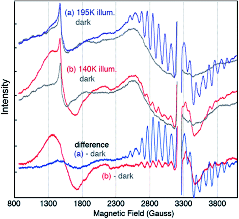 | ||
| Fig. 1 EPR spectra of PSII samples in glycerol illuminated for 10 minutes at (a) 195 K (blue) (b) 140 K with NIR (red) along with corresponding dark (grey) EPR spectra. The difference spectra are between the spectra after illumination and the spectra of the same dark-adapted sample. The large intensity from YD˙ in each spectrum has been removed for clarity (∼3200 G). Spectrometer condition: microwave frequency, 9.22 GHz; field modulation amplitude, 32 G at 100 KHz; microwave power, 20 mW. The spectra are collected at 8 K. | ||
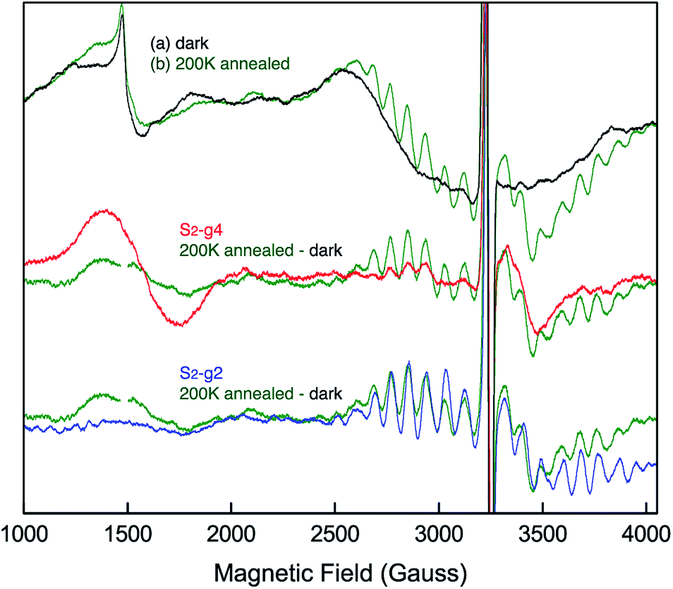 | ||
| Fig. 2 EPR spectral changes of the sample annealed at 200 K (green) after 140 K NIR illumination. The difference spectrum between annealed sample (green) and dark is compared to the 140 K NIR illuminated minus dark or S2-g4 (red) and 195 K illuminated minus dark or S2-g2 (blue) samples. The spectra are collected at 8 K. Spectrometer condition: microwave frequency, 9.22 GHz; field modulation amplitude, 32 G at 100 KHz; microwave power, 20 mW. | ||
O2 activity of the g2 rich and g4 rich spinach PSII
It is known that PSII samples from spinach in the S2 state in glycerol buffer have a dominant S2-g2 signal with only a trace of the S2-g4 signal for 195 K illumination, while the PSII in sucrose buffer have both S2-g2 signal and S2-g4 signal in almost 50![[thin space (1/6-em)]](https://www.rsc.org/images/entities/char_2009.gif) :50 ratio.41 We observe a similar trend in the EPR spectra of these samples are shown in Fig. 1 (glycerol) and Fig. S3 (sucrose) in the ESI.† To check the activity of the S2-g4-rich and S2-g2-rich PSII samples, the O2 evolution activity of both samples are compared by dividing the same batch of PSII thylakoid samples into two parts and transferring one part into glycerol buffer, and the other into sucrose buffer [50 mM MES–NaOH (pH 6.0), 5 mM MgCl2, 5 mM CaCl2 and 15 mM NaCl, 0.4 M sucrose]. The O2 activity was very similar between the two samples, giving rates of 420 ± 10 μmol of O2 per mg of Chl per h in glycerol buffer and 408 ± 10 μmol of O2 per mg of Chl per h in sucrose buffer. These measurements were performed with three different sample preparations. The results shows that the number of the active centers is more or less the same in the two samples, while the fraction of centers that can be cryo-trapped in the S2-g4 or the S2-g2 spin states is significantly different, depending on the buffer conditions.
:50 ratio.41 We observe a similar trend in the EPR spectra of these samples are shown in Fig. 1 (glycerol) and Fig. S3 (sucrose) in the ESI.† To check the activity of the S2-g4-rich and S2-g2-rich PSII samples, the O2 evolution activity of both samples are compared by dividing the same batch of PSII thylakoid samples into two parts and transferring one part into glycerol buffer, and the other into sucrose buffer [50 mM MES–NaOH (pH 6.0), 5 mM MgCl2, 5 mM CaCl2 and 15 mM NaCl, 0.4 M sucrose]. The O2 activity was very similar between the two samples, giving rates of 420 ± 10 μmol of O2 per mg of Chl per h in glycerol buffer and 408 ± 10 μmol of O2 per mg of Chl per h in sucrose buffer. These measurements were performed with three different sample preparations. The results shows that the number of the active centers is more or less the same in the two samples, while the fraction of centers that can be cryo-trapped in the S2-g4 or the S2-g2 spin states is significantly different, depending on the buffer conditions.
Mn K-edge spectra
Fig. 3a shows the Mn XANES spectra of the two S2 spin states (HS S2 and LS S2), together with S1 and S3 states. In the presence of glycerol as a cryo-protectant, the majority of the PSII centers are in the LS S2 state when illuminated at 195 K, as observed in the EPR spectra (see Fig. 1 ((a) minus dark)). On the other hand, illumination at 140 K generates a large fraction of the PSII centers in the HS S2 state. Using the estimated ratio of S2-g2 MLS intensity between the samples under the two illumination conditions (195 K illuminated vs. the 140 K illuminated samples), it is inferred that a minor fraction (∼20%) of LS S2 state is present in the samples illuminated at 140 K. The corresponding amount of LS S2 state spectrum was subtracted from the XAS spectrum of 140 K NIR illuminated sample to obtain the pure HS S2 XAS spectrum. This is based on the assumption that 195 K illuminated and 140 K NIR illuminated samples consist of a linear combination of the HS and LS S2 states. The pure LS S2 XAS spectra were also obtained by the same method. The untreated XAS spectra from the 195 K illuminated and the 140 K NIR illuminated samples are shown in Fig. S4 in the ESI.†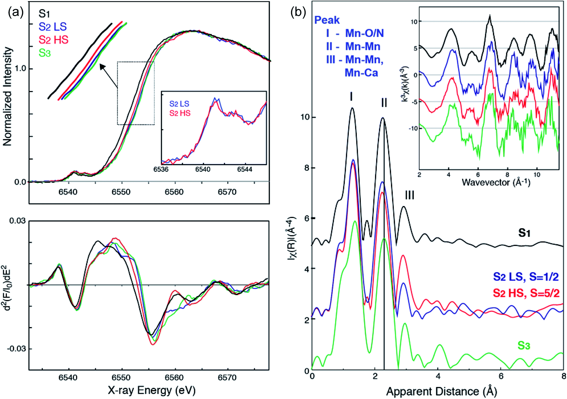 | ||
| Fig. 3 (a) Mn XANES spectra (top) and their second derivative spectra (bottom) of HS (red) and LS (blue) S2 states, in comparison with S1 (black) and S3 (green) states. Mn preedge of HS (red) and LS (blue) S2 states (inset). (b) Mn EXAFS spectra of HS (red) and LS (blue) S2 states, in comparison with S1 (black) and S3 (green) states. k3-Weighted EXAFS spectra (inset) and their Fourier-transformed spectra of HS (red) and LS (blue) S2 states, in comparison with S1 (black) and S3 (green) states are shown. Prominent changes in peak II of the FT spectra between the different states are indicated by a line (black). All spectra are shown in the same scale but with a vertical offset. Pure (deconvoluted) S-states are shown in the figure. | ||
Interestingly, the XANES rising edge position of the HS S2 state is slightly but noticeably lower in energy than that of the LS S2 state as shown in Fig. 3a. While the edge positions of LS S2 and S3 states are very close, their spectral shapes are not exactly the same. This difference is more clearly seen in the 2nd derivative spectra (Fig. 3a bottom). The inflection point energy obtained from the 2nd derivative XANES spectra are, 6552.11 eV (S1), 6552.89 (S2 HS), 6553.44 (S2 LS), and 6553.71 (S3). It is often difficult to compare these numbers with literature values due to different procedures for generation of the 2nd derivative spectra. Therefore, we compared XANES spectra of all S-states treated in the same way, to eliminate any ambiguity that may arise from such data treatment. We further note that the inflection point energy could be a possible indicator of Mn charge density, although multiple-scattering effects in the XANES region could mask such changes when the structural changes are accompanied by oxidation state changes. For this reason, we cautiously state that the edge shift observed in the HS and LS S2 state suggests a change in charge density of Mn in these two states. The HS S2 state might be slightly lower in the effective positive charge density on Mn compared to the LS S2 state. We confirmed that there is no indication of MnII being released during the 140 K NIR illumination by monitoring the presence of the MnII EPR signal since such an effect will also lower the Mn XANES edge position. Another potential cause for lowering the Mn edge position is the presence of a fraction of the S1 state in the HS S2 sample due to the low temp. illumination. We excluded this possibility based on the results of the annealing experiments (Fig. 2). After annealing the S2-g4 sample to 200 K, the multiline (g = 2) spectra increased to 70% compared to the S2-g2 state spectra. On the other hand, the g = 4 part of the annealed spectra was reduced to 30% of the S2-g4 spectra.
In addition, we investigated the Mn XANES pre-edge peaks of the two states, as it serves as another indicator of the effective charge density. The pre-edge spectra are slightly, but noticeably different in the LS S2 and HS S2 states (Fig. 3a inset). The pre-edge spectra were fit with a pseudo-Voigt line with a 1:1 ratio of Lorentzian and Gaussian functions and the peak area was compared between these two states. The number of the pre-edge components and their positions were estimated by the 2nd derivative spectra. The area of the pre-edge peak was 0.22 for LS S2 and 0.24 for HS S2 (Fig. S5 and Table S1 in the ESI†).71 While the slightly larger pre-edge area observed in HS S2 may indicate a more distorted ligand environment in this state as compared to LS S2, the difference is rather small for drawing any concrete conclusions.
Fig. 3b shows the EXAFS spectra of the two S2 spin states, together with the S1 and S3 state spectra. A comparison of the HS and LS S2 state spectra shows noticeable differences in the 2nd Fourier transform (FT) peak width and intensity as well as the 3rd FT peak intensity, which is significantly higher in the HS S2 state spectrum. The 2nd FT peak corresponds to the di-μ-oxo bridged Mn–Mn interactions around 2.7 Å and the 3rd FT peak arises from the contribution of mono-μ-oxo bridged Mn–Mn and Mn–Ca interactions around 3.3 Å. Such differences are also visible in the EXAFS oscillation in the k-space spectra (Fig. 3b inset). Furthermore, both HS and LS S2 spectra differ from the S3 state spectrum, suggesting that the structural geometries in these three states are not the same. Detailed EXAFS analysis is discussed in the next section.
Mn EXAFS curve fitting
Mn EXAFS curve fitting of the HS and LS S2 states were carried out to extract structural parameters of the Mn cluster in these states. Descriptions of the parameters used are provided in the ESI.†Fig. 4 shows fit results, and the fit parameters are summarized in Table 1. Structures for LS and HS S2 state have been proposed previously based on EPR and quantum chemical calculations,21 and we therefore used those as starting structural models for fitting the EXAFS data.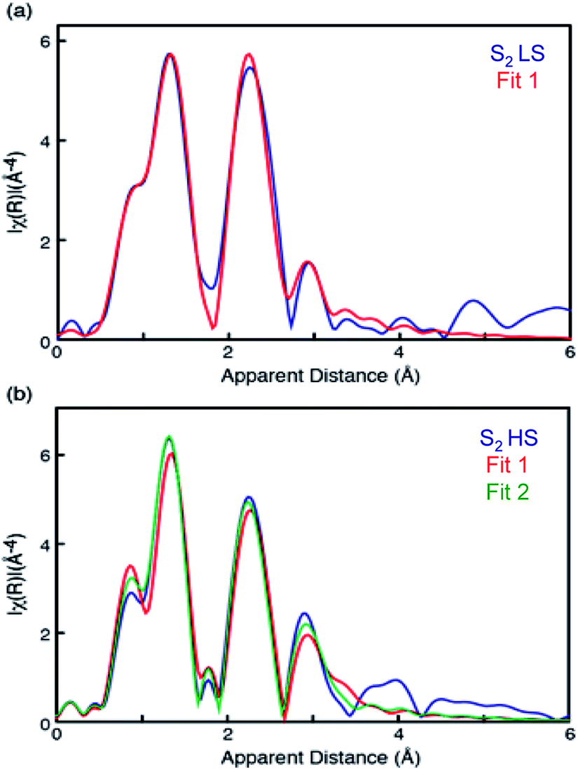 | ||
| Fig. 4 EXAFS curve fitting results of HS (bottom) and LS (top) S2 states. The parameters are listed in Table 1. | ||
| Sample | Fit # | Shell | N | R/Å | σ 2/Å | R/% |
|---|---|---|---|---|---|---|
| a S02 was set to 0.85. σ2 is the Debye–Waller factor, R (%) shows the goodness of fit. The fit range of all the spectra are k = 2.4–11.3 Å−1 (R = 1–4.2 Å). Note that for Mn–Mn interactions, N = 1.5 implies that there are three similar interactions within the cluster, as the number of interactions is divided by the number of Mn in the cluster (i.e. 3/4 = 1.5) to be normalized it to per Mn. Similarly, Mn–Ca 0.5 means there are two similar Mn–Ca interactions within the cluster (i.e. 2/4 = 0.5). | ||||||
| LS S2 | 1 | Mn–O | 4 | 1.83 (0.01) | 0.005 (0.001) | 4.2 |
| Mn–O(N) | 2 | 2.00 (0.03) | 0.004 (0.001) | |||
| Mn–Mn | 1.5 | 2.72 (0.02) | 0.002 (0.002) | |||
| Mn–Mn | 0.5 | 3.24 (0.11) | 0.005 (0.001) | |||
| Mn–Ca | 0.75 | 3.36 (0.01) | 0.007 (0.001) | |||
| Mn–Ca | 0.25 | 3.89 (0.01) | 0.005 (0.001) | |||
| E 0 (eV) = −9.3 | ||||||
| HS S2 | 1 | Mn–O | 4 | 1.85 (0.03) | 0.005 (0.001) | 2.6 |
| Mn–O(N) | 2 | 2.05 (0.07) | 0.006 (0.006) | |||
| Mn–Mn | 1.5 | 2.74 (0.03) | 0.004 (0.003) | |||
| Mn–Mn | 0.5 | 3.30 (0.07) | 0.001 (0.001) | |||
| Mn–Ca | 0.75 | 3.36 (0.01) | 0.007 (0.001) | |||
| Mn–Ca | 0.25 | 4.09 (0.01) | 0.015 (0.001) | |||
| Mn–C | 3 | 4.39 (0.17) | 0.002 (0.001) | |||
| E 0 (eV) = −8.1 | ||||||
| 2 | Mn–O | 4 | 1.84 (0.03) | 0.005 (0.003) | 1.2 | |
| Mn–O(N) | 2 | 2.02 (0.06) | 0.007 (0.008) | |||
| Mn–Mn | 1 | 2.72 (0.02) | 0.001 (0.001) | |||
| Mn–Mn | 1 | 3.30 (0.05) | 0.005 (0.001) | |||
| Mn–Ca | 0.75 | 3.26 (0.14) | 0.007 (0.001) | |||
| Mn–Ca | 0.25 | 4.09 (0.01) | 0.006 (0.001) | |||
| Mn–C | 3 | 4.35 (0.14) | 0.004 (0.001) | |||
| E 0 (eV) = −11.2 | ||||||
The LS S2 state fits well with the proposed open cubane-like structure.16,21 In this structure, there are three short Mn–Mn interactions around 2.7–2.8 Å and one long Mn–Mn interaction around 3.3 Å (LS S2 – fit #1 in Fig. 4 and Table 1). For the HS S2 state, the left-open structural model was suggested by Pantazis et al. and Isobe et al. from QM/MM calculations (Scheme 2).21,47 In this model, the numbers of short and long Mn–Mn interactions and Mn–Ca interactions in the HS S2 state remain the same as in the LS S2 model. Therefore, the same parameters obtained from the LS S2 fit (LS S2 – fit #1) were used as starting parameters (HS S2 – fit #1). In the experimental spectrum of HS S2, the 3rd FT peak intensity increases noticeably, while the 2nd FT peak becomes narrower than that of the S2 LS spectrum. In HS S2 (fit #1), the atomic distances remained similar to the initial parameters. The weaker FT peak II intensity and the stronger FT peak III intensity were compensated by Debye Waller factors. While FT peak II could be fit with three Mn–Mn interactions with an average distance of 2.73 Å, the presence of a longer ∼2.8 Å Mn–Mn interaction was not preferable. This observation suggests that a complete cubane with MnD1, MnC2, MnB3, and Ca cannot be formed in this state; as such a structure typically will have high distance heterogeneity in the range of 2.7 to 2.8 Å. We also tested a hypothetical model where one of the three Mn–Mn short distances elongates, as it would in the presence of a mono-μ-oxo-like bridge, i.e. giving a short (2.7–2.8 Å) and long (∼3.3 Å) Mn–Mn distances ratio of 1:1 (HS S2 – fit #2). The fit quality was improved by 50% for this model. In a later section, we further discuss (a) whether such a structure is possible, (b) the interconversion between HS and LS form in the S2 state, and (c) the relation of the two S2 isomers to the formation of the S3 state.
Mn Kβ1,3/Kβ′ XES
XES Kβ1,3/Kβ′ transitions provide complementary information to XANES, by probing the Mn 3p to 1s emission process that is sensitive to the number of unpaired 3d electrons through 3d/3p spin exchange interactions. We measured the Kβ1,3 XES spectra of the LS and HS S2 states. We observe a slight shift in the Kβ1,3 emission spectra between the LS and HS S2 states (Fig. 5). Fig. S6† shows raw and smoothed data for the Kβ1,3/Kβ′ XES transitions for LS and HS S2 states along with the residual plot. The spectra were smoothed using a sum of nonlinear lineshapes. We observe that the spectrum of the LS S2 state is at a slightly lower energy than the HS S2 state, as becomes evident in the difference spectra of the LS and HS S2 states (Fig. 5). With an increase in the oxidation state of Mn, fewer unpaired 3d valence electrons can interact with the 3p hole, leading to a decrease in the magnitude of 3p–3d exchange interaction, which results in the Kβ1,3 emission spectra shifting to a lower energy. Hence, the LS S2 state might have slightly higher effective positive charge density on Mn compared to the HS S2. This is in agreement with the changes observed in the XANES spectra reported in the earlier section.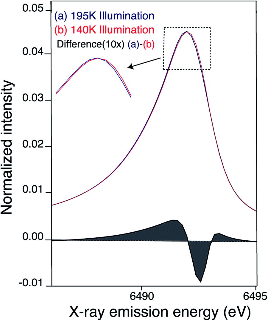 | ||
| Fig. 5 Kβ1,3 emission (smoothed) spectra of S2 sample obtained by (a) 195 K (blue) (b) 140 K NIR illumination (red). Difference between the Mn Kβ1,3 XES of PS II (at 10× enlargement) 195 illuminated – 140 K NIR illuminated S2 state is shown in black. The 195 K emission spectra from Fig. S6† was smoothed by fitting a sum of two asymmetric orthogonal lineshape functions. The 140 K spectrum is fit by a superposition of the 195 K fit and additional orthogonal lineshape functions. In order to obtain an unstructured residual a single additional orthogonal lineshape function is adequate, but significant structure is present in the residual if no additional lines are added. The minor fraction of the other state (HS S2 in case of LS S2 and vice versa) present is not subtracted in the spectra presented here. | ||
Discussion
The nature of the two isomers in the S2 state of higher plant PSII was investigated using X-ray spectroscopy with the support of EPR spectroscopy. We have observed the XAS (XANES and EXAFS) and XES spectral changes between the HS and LS S2 species, and here we discuss possible structural models and the transition phenomena, with a comparison to the proposed models in the literature.First, the fact that the population of the LS and HS S2 species seems to shift depending on the buffer conditions implies that some variation of the XANES edge positions for the S2 state shown in the literature may contain this effect since this kind of isomorphism was known but not differentiated until recently. Nevertheless, the LS S2 state should be the dominant spin state in the literature studies, when glycerol buffer is used.7,11,16,72
Structural models of the high-spin and low-spin S2 states
The differences observed in the XAS spectra provide evidence for the different electronic structure and the metal–metal atomic distances in the HS and LS S2 states. The HS and LS structural models that involve interconversion of the MnIII position in these two species have been proposed by Pantazis et al.21 and Isobe et al.47 based on EPR results and from quantum chemical calculations. In the LS S2, MnIII is located at the MnD1 position that is ligated to His332 of D1 chain, while in the HS S2 state MnIII is at the MnA4 position of the cluster, which has two water ligands (Fig. S7†). The EXAFS curve fitting results match with the result that the LS S2 state is an open cubane-like structure in which MnIII is at the MnD1 site, as previously suggested. While in general EXAFS is not a technique that can be used to conclusively point to a single, unique, structural model,73 the observed peak intensity change in the FT EXAFS spectra is clear evidence of the structural differences between the two spin states. The EXAFS curve fitting results suggests that the ratio of short and long Mn–Mn interactions may be different in the HS and LS S2 forms. The HS S2 form could exhibit two short and two long Mn–Mn interactions, in which the central oxygen (O5) is required to be nearly at the center between MnA4 and MnD1. Fig. 6 shows the possible structural changes of the HS and LS S2 states, based on the EXAFS observation. In these models, we kept the formal oxidation state assignment of each Mn as suggested by Pantazis et al.21 and Isobe et al.,47 in which MnIII is located at the MnD1 in LS S2 form, while it is at the MnA4 in HS form. Within our current knowledge, it is reasonable to think that the Stotal = 1/2 being formed with anti-ferromagnetically-coupled MnIII and MnIV along with two anti-ferromagnetically-coupled MnIV, and Stotal = 5/2 being formed with three ferro-magnetically coupled MnIV in the cubane moiety with anti-ferromagnetically-coupled MnIII at MnA4. | ||
| Fig. 6 Proposed distance changes during the S1–S2–S3 transitions, based on the current EXAFS data and proposed models by Cox et al. and Siegbahn et al.12,20,52,60 | ||
The XANES edge position of the HS S2 appears slightly lower than that of the LS form, suggesting that the effective charge density of the HS form may be lower than that of LS. This observation is also supported by the Mn Kβ1,3 XES results. As formal oxidation state and number of unpaired spins should be the same between HS and LS S2 state (although the total number of spin differs due to exchange coupling of the four Mn), one speculation is that the different protonation states of the ligand oxygen or geometry of the cluster in these two states shifts the effective charge density on Mn. If the protonation state of a ligand oxygen is different, O5 located between MnD1 and MnA4 is one possible candidate that could weaken two Mn–Mn interactions and therefore result in two long (>3.0 Å) Mn–Mn interactions. The deprotonated O5 in the LS S2 form is confirmed by EXAFS that shows all three distances, MnA4–MnB3, MnB3–MnC2, MnC2–MnD1, to be around ∼2.74 Å.16 On the contrary, if O5 is protonated in the HS form, both Mn1D–Mn3B and Mn4D–Mn3B will be elongated. The difference in oxo-bridge protonation state may affect the effective charge density on Mn. However, the S2 structure with protonated O5 in the MnIII,IV,IV,IV4 oxidation state is expected to be energetically much higher (∼25 to 30 kcal) compared to the deprotonated O5 (Fig. 7). This is also observed in a recent theoretical study by Krewald et al.10 Thus, this S2 state cannot exist as a stable form, unless there are other factors that stabilize such a structure. Hence, the difference in the geometry between the two states may be the reason for the shift in effective charge density in the HS S2 state.
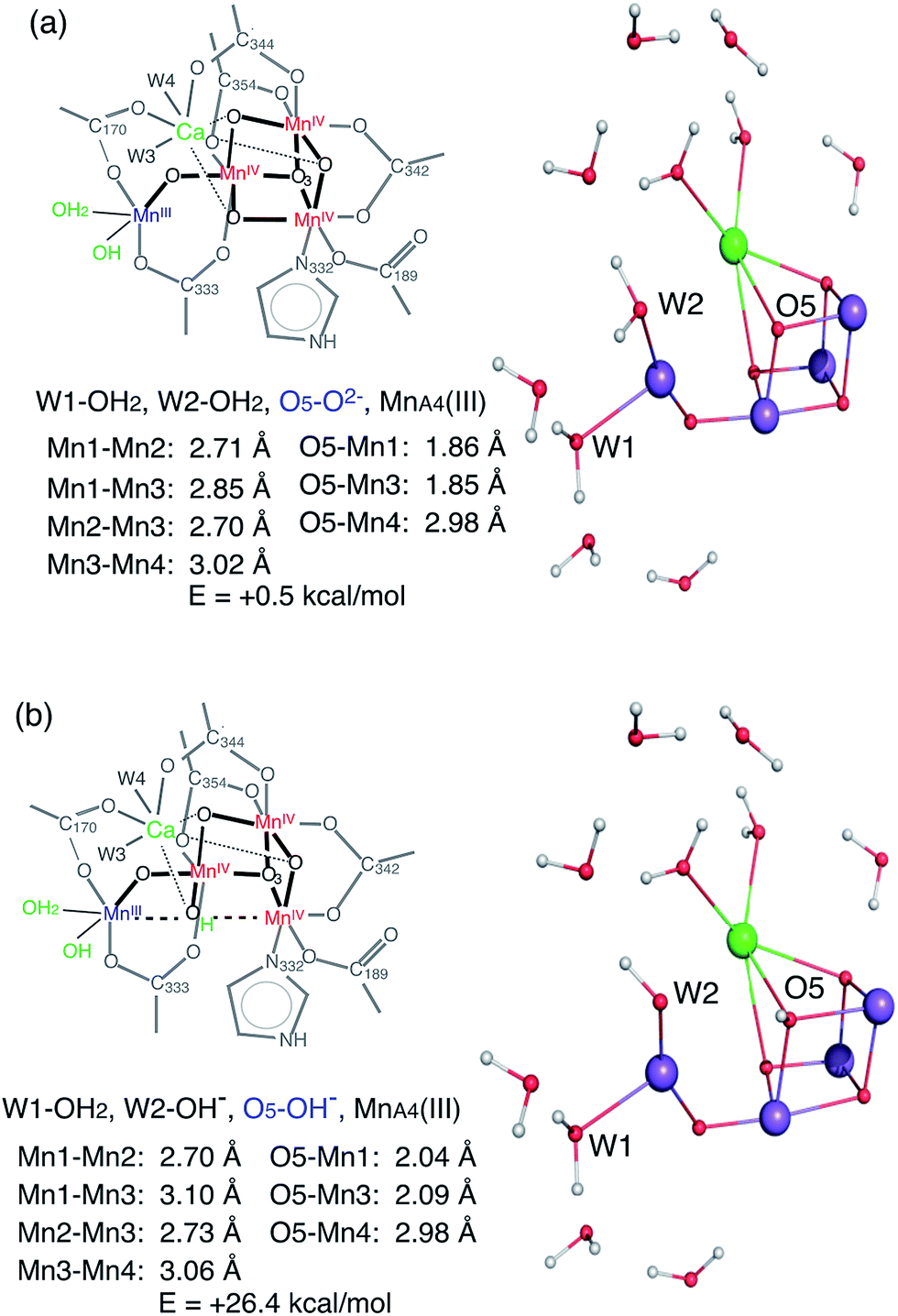 | ||
| Fig. 7 Two possible HS S2 models, with deprotonated (top) and protonated (bottom) O5, determined by QM calculations. | ||
As shown in Fig. 3a, the EXAFS spectra of HS and LS S2 states and the S3 state are all different. This implies that the atomic distances of these three forms are different. The structural model of HS S2 state proposed from the QM calculations is very similar to one of the two structural models proposed by us for the S3 state in a previous study.16 Studies by Cox et al. with EPR and QM calculations20 and Siegbahn et al. with earlier QM calculations,52 suggest that the S2 LS and S3 structure share the same Mn3Ca geometry with an open-cubane structure, except for an additional water molecule ligated in the open coordination site of MnD1 in the S3 state. Our group has proposed a S3 state structure to comprise a closed-cubane structural motif, based on the EXAFS studies (Fig. 6) that showed an elongation of Mn–Mn distances within the cubane-motif. The rationale of our proposal is from inorganic model compound studies where the elongation of metal–metal distances is observed when the cubane is formed.74,75 A similar elongation of the metal–metal distances is visible in the S3 EXAFS spectrum (i.e. while all three di-μ-oxo Mn–Mn distances are ∼2.74 Å in the S2 state, it is more distributed over the range of 2.72–2.82 Å in the S3 state).16
In the current study, we observed that the HS S2 EXAFS is different from that of S3 state, suggesting that the geometries of HS S2 and S3 state structures are likely different. One possibility is that, as depicted in Fig. 6, in LS S2 O5 is bound to MnA4, while in HS S2 it is more or less equidistant from MnA4 and MnD1. In S3 state, the O5 position is shifted to MnD1. However, an uncertainty remains if the S3 state has a large heterogeneity (EPR active and EPR silent species), as suggested by Boussac et al.45 and Cox et al.20 based on EPR studies. Then the EXAFS spectrum under our experimental condition could be a mixture of the EPR active and the EPR silent species. Further studies of this potential heterogeneity are necessary. Also, we cannot eliminate the possibility of the inserted water model suggested by Cox et al.20 and Siegbahn et al.,52 if the elongation of the metal–metal distances in the S3 state occurs by the expansion of the open-cubane moiety due to the effect of newly inserted water into the open Mn1 site (Fig. 6).
Transition process between the S1, S2, to S3 states
Currently, the radiation-damage-free dark state structure published by Suga et al. with 1.95 Å resolution4 serves as the most reliable foundation for considering possible distance changes in the higher S-states. Mn–Mn distances and number of interactions in the crystal structure matches reasonably well with the structural parameters obtained from earlier EXAFS studies of the S1 state (i.e. there are three short 2.7–2.8 Å Mn–Mn interactions and one long ∼3.3 Å Mn–Mn interaction in addition to three Mn–Ca interactions).16,59,60 One of the remaining uncertainties in the S1 structure, however, is the protonation state of O5. Suga et al. suggest O5 to be protonated, based on the long MnA4–O5 and MnD1–O5 distances4 in which the O5 position was obtained from the omit map. However, there is another explanation that proposes a deprotonated O5 in the S1 state. In the following section, we discuss these two possibilities, case (1) for protonated O5 and case (2) for deprotonated O5 in the S1 state, in relation to the S2 state formation (Fig. 8).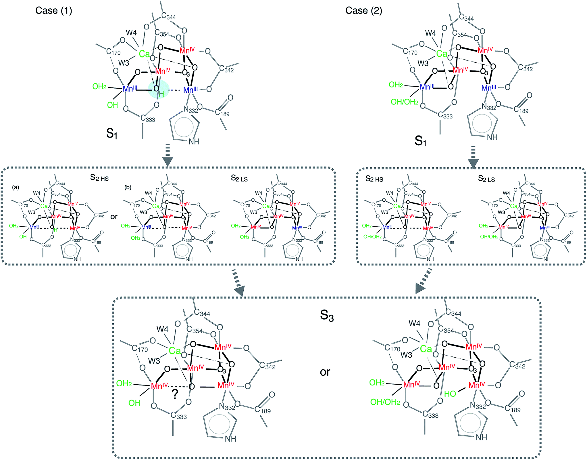 | ||
| Fig. 8 Structural model showing two possible reaction pathways during S1–S2–S3 transitions with protonated O5 (case 1) and deprotonated O5 (case 2). | ||
In case (1), the O5 proton needs to move away from the OEC upon S1 to S2 (via 200 K illumination or RT laser flash) transition, as it is most likely that O5 is deprotonated in the LS S2 form. If the protonation state is different between HS and LS S2 states, one possible reason for this to occur is that O5 is protonated in the S1 state, and remains as it is in the HS S2 (case (1), S2 HS (a) in Fig. 8). Small structural or chemical changes that are required for the proton motion could be prohibited under the illumination condition at 140 K with NIR illumination while going to the ‘native’ S2 state may require an illumination at higher temperature. As previously discussed, the S2 structure with protonated O5 is energetically much higher than the deprotonated one (Fig. 7), which makes this model highly unlikely. Moreover, it is difficult to rationalize an observed reversibility between LS S2 and HS S2 form with the O5-protonated model. Therefore, the O5 proton in the S1 state needs to move to a nearby ligand in the S1 to HS S2 transition (case (1), S2 HS (b) in Fig. 8). The EXAFS curve fitting results in this study suggest that there could be two elongated Mn–Mn interactions longer than 3 Å, and two di-μ-oxo bridged Mn–Mn interactions at ∼2.7 Å. Such a structure is different from the one proposed from the theoretical studies.21,47 Although we cannot completely rule out a model that contains three 2.7 Å Mn–Mn and one 3.3 Å Mn–Mn, a complete cubane formation at HS S2 state seems to be less likely from the current EXAFS data due to decreased heterogeneity around 2.7 Å interactions. The structural differences in HS and LS S2 states could be reasoned by O5 position moving closer to Mn1D upon oxidation of Mn1D from MnIII to MnIV during the S1 to HS S2 state transition, but Mn1D–O5 is weakly bound with a distance longer than 2 Å. In case (2) in which O5 is deprotonated in the S1 state, a similar argument to case (1) is applicable (Fig. 8).
The question arises whether the HS S2 state populated by 140 K NIR illumination, that we observed in this study, is the same as the S2 state with enhanced g = 4 signals that is observed at higher temperature illumination (200 K illumination or laser flash at room temperature) under certain buffer conditions (e.g. with sucrose buffer) or additional chemical treatments (e.g. with a substitution of Ca2+ by Sr2+). Moreover, whether the HS and LS S2 species is populated under physiological conditions and such heterogeneity plays a role in the S-state advancement and the catalytic reaction still remains unanswered. While this question requires the room temperature study, here we speculate if the g = 4 species made under different conditions are always the same. It has been suggested that any changes that disturb the hydrogen bond network around the OEC influence the electronic properties of MnA4 through the W1 and/or W2 ligands that are ligated to this Mn.44 There is a trend that any changes in the electron donating effect in ligands of MnA4 favor this site to have a lower Mn oxidation state (i.e. MnIII).44 The high-resolution crystal structure of the T. vulcanus PSII3 has shown that the hydrogen bond network around OEC is extended from W1 and W2 of MnA4 to D1–D61 (Fig. S7†). Pokhrel et al. suggested that this hydrogen bonding network of W1 and W2 determines the equilibrium between the g = 2 and g = 4 forms of the OEC in the S2 state.44 As a consequence, we can speculate that the HS S2 EPR signal around the g = 4 region changes and its exact g-value (i.e. the zero-field splitting) is highly affected by such effects. The fact that we observe changes in HS S2 state from LS S2 state implies that the OEC structure that causes the g ∼ 4 EPR signal, whether by buffer contents or chemical treatments, is different from that of the g = 2 species. A question still remains if all the g = 4 species observed in the EPR spectra represents the same structure. This may not be the case if some of the g = 4 signals under certain conditions are not from the Stotal = 5/2 ground state, but from the excited state of a different ground state spin configuration, thus these signals may represent other ground state spin configurations. For example, the temperature-dependent EPR signal from a weakly-coupled Mn(III/IV) dimer core has been reported in a model system.76 In this case, the 16-line spectrum of the ground state (Stotal = 1/2) and the g ∼ 5 spectrum from the excited state (Stotal = 3/2) are observed. No observation of temperature dependence when going from S2-g2 to S2-g4 EPR signals in PSII suggest that both the signals studied here arise from the ground state. Also, since the proposed models available are based on EPR measurements that are all measured at low temperature, the S2 species that exist in room temperature still remains unknown.
In the current study, we use spinach PSII to investigate the S2-g2 and S2-g4 states. Unlike spinach PSII in which the S2-g4 signal is observed under certain buffer conditions, there are additional EPR signals along with the S2-g4 signal in Synechococcus PSII wild type. In these samples, g = 6 to 10 signals are also observed when samples are IR illuminated, and the pure g = 4 signal is only observed when the native Ca2+ or Cl− is substituted. Nevertheless, the intensity of these low EPR field signals are weak, and it suggests that S2-g2 state is the dominant species in the wild type. The reason for such species dependence is not known, as the crystal structure is only available for the Synechococcus PSII. However, it is likely due to small differences in the hydrogen-bonding network that extends from W1 and W2 of the OEC to the water channel leads to subtle differences in the electronic structure.
Conclusions
We have investigated the structure and the electronic structure of the two spin-isomers in the PSII S2 intermediate states. The XAS data suggests different structural configurations for the HS and LS S2 states. It also suggests that their structures are different from the subsequent S3 state. Whether the HS S2 state serves as an intermediate state between the LS S2 and the S3 state as proposed from theoretical modeling is still an open question, and the high-resolution crystal structure of these intermediate states, possibly at the room temperature is necessary to resolve it. Despite such noticeable structural differences during the catalytic pathway due to the likely modification of the hydrogen-bonding network, the O2 evolution activity remains similar for both spin forms. This implies a certain flexibility of the OEC in its geometric and electronic structure under physiological conditions, although one state may be more preferable than the other.Acknowledgements
This work was supported by NIH Grant GM 55302, and by the Director of the Office of Science, Office of Basic Energy Sciences (OBES), Division of Chemical Sciences, Geosciences, and Biosciences, DOE, under Contract DE-AC02-05CH11231. Synchrotron facilities were provided by the Stanford Synchrotron Radiation Lightsource (SSRL) operated by DOE, OBES. The SSRL Biomedical Technology program is supported by the NIH, the National Center for Research Resources, and the DOE Office of Biological and Environmental Research. J. Y. thanks the Human Frontier Science Project Award No. RGP0063/2013.References
- Photosystem II: The Light-Driven Water:Plastoquinone Oxidoreductase, ed. T. Wydrzynski and S. Satoh, Springer, Dordrecht, 2005 Search PubMed.
- G. Renger, in Primary processes of photosynthesis, RSC Publishing, 2008, vol. 2, p. 237 Search PubMed.
- Y. Umena, K. Kawakami, J.-R. Shen and N. Kamiya, Nature, 2011, 473, 55 CrossRef CAS PubMed.
- M. Suga, F. Akita, K. Hirata, G. Ueno, H. Murakami, Y. Nakajima, T. Shimizu, K. Yamashita, M. Yamamoto, H. Ago and J.-R. Shen, Nature, 2015, 517, 99 CrossRef CAS PubMed.
- B. Kok, B. Forbush and M. McGloin, Photochem. Photobiol., 1970, 11, 457 CrossRef CAS PubMed.
- H. Dau and M. Haumann, Coord. Chem. Rev., 2008, 252, 273 CrossRef CAS.
- M. Haumann, C. Muller, P. Liebisch, L. Iuzzolino, J. Dittmer, M. Grabolle, T. Neisius, W. Meyer-Klaucke and H. Dau, Biochemistry, 2005, 44, 1894 CrossRef CAS PubMed.
- J. Yano and V. K. Yachandra, Chem. Rev., 2014, 114, 4175 CrossRef CAS PubMed.
- L. V. Kulik, B. Epel, W. Lubitz and J. Messinger, J. Am. Chem. Soc., 2007, 129, 13421 CrossRef CAS PubMed.
- V. Krewald, M. Retegan, N. Cox, J. Messinger, W. Lubitz, S. DeBeer, F. Neese and D. A. Pantazis, Chem. Sci., 2015, 6, 1676 RSC.
- J. Messinger, J. H. Robblee, U. Bergmann, C. Fernandez, P. Glatzel, H. Visser, R. M. Cinco, K. L. McFarlane, E. Bellacchio, S. A. Pizarro, S. P. Cramer, K. Sauer, M. P. Klein and V. K. Yachandra, J. Am. Chem. Soc., 2001, 123, 7804 CrossRef CAS PubMed.
- J. Yano and V. K. Yachandra, Photosynth. Res., 2007, 92, 289 CrossRef CAS PubMed.
- T. Glaser, B. Hedman, K. O. Hodgson and E. I. Solomon, Acc. Chem. Res., 2000, 33, 859 CrossRef CAS PubMed.
- E. I. Solomon, B. Hedman, K. O. Hodgson, A. Dey and R. K. Szilagyi, Coord. Chem. Rev., 2005, 249, 97 CrossRef CAS.
- P. Glatzel, H. Schroeder, Y. Pushkar, T. Boron III, S. Mukherjee, G. Christou, V. L. Pecoraro, J. Messinger, V. K. Yachandra, U. Bergmann and J. Yano, Inorg. Chem., 2013, 52, 5642 CrossRef CAS PubMed.
- C. Glöckner, J. Kern, M. Broser, A. Zouni, V. Yachandra and J. Yano, J. Biol. Chem., 2013, 288, 22607 CrossRef PubMed.
- C. F. Yocum, Coord. Chem. Rev., 2008, 252, 296 CrossRef CAS.
- R. J. Debus, Coord. Chem. Rev., 2008, 252, 244 CrossRef CAS PubMed.
- T. S. Kuntzleman and A. Haddy, Photosynth. Res., 2009, 102, 7 CrossRef CAS PubMed.
- N. Cox, M. Retegan, F. Neese, D. A. Pantazis, A. Boussac and W. Lubitz, Science, 2014, 345, 804 CrossRef CAS PubMed.
- D. A. Pantazis, W. Ames, N. Cox, W. Lubitz and F. Neese, Angew. Chem., Int. Ed., 2012, 51, 9935 CrossRef CAS PubMed.
- N. Cox and J. Messinger, Biochim. Biophys. Acta, Bioenerg., 2013, 1827, 1020 CrossRef CAS PubMed.
- H. Nilsson, T. Krupnik, J. Kargul and J. Messinger, Biochim. Biophys. Acta, Bioenerg., 2014, 1837, 1257 CrossRef CAS PubMed.
- H. Isobe, M. Shoji, S. Yamanaka, Y. Umena, K. Kawakami, N. Kamiya, J. R. Shen and K. Yamaguchi, Dalton Trans., 2012, 41, 13727 RSC.
- G. C. Dismukes and Y. Siderer, Proc. Natl. Acad. Sci. U. S. A., 1981, 78, 274 CrossRef CAS.
- Ö. Hansson and L.-E. Andréasson, Biochim. Biophys. Acta, 1982, 679, 261 CrossRef.
- G. W. Brudvig, J. L. Casey and K. Sauer, Biochim. Biophys. Acta, 1983, 723, 366 CrossRef CAS.
- J. C. de Paula and G. W. Brudvig, J. Am. Chem. Soc., 1985, 107, 2643 CrossRef CAS.
- D. W. Randall, B. E. Sturgeon, J. A. Ball, G. A. Lorigan, M. K. Chan, M. P. Klein, W. H. Armstrong and R. D. Britt, J. Am. Chem. Soc., 1995, 117, 11780 CrossRef CAS.
- J. M. Peloquin, K. A. Campbell, D. W. Randall, M. A. Evanchik, V. L. Pecoraro, W. H. Armstrong and R. D. Britt, J. Am. Chem. Soc., 2000, 122, 10926 CrossRef CAS.
- M.-F. Charlot, A. Boussac and G. Blondin, Biochim. Biophys. Acta, Bioenerg., 2005, 1708, 120 CrossRef CAS PubMed.
- A. Haddy, Photosynth. Res., 2007, 92, 357 CrossRef CAS PubMed.
- N. Cox, L. Rapatskiy, J. H. Su, D. A. Pantazis, M. Sugiura, L. Kulik, P. Dorlet, A. W. Rutherford, F. Neese, A. Boussac, W. Lubitz and J. Messinger, J. Am. Chem. Soc., 2011, 133, 3635 CrossRef CAS PubMed.
- J. L. Casey and K. Sauer, Biochim. Biophys. Acta, 1984, 767, 21 CrossRef CAS.
- J. L. Zimmermann and A. W. Rutherford, Biochim. Biophys. Acta, 1984, 767, 160 CrossRef CAS.
- A. Haddy, K. V. Lakshmi, G. W. Brudvig and H. A. Frank, Biophys. J., 2004, 86, 12A Search PubMed.
- A. Boussac, J.-J. Girerd and A. W. Rutherford, Biochemistry, 1996, 35, 6984 CrossRef CAS PubMed.
- A. Boussac, S. Un, O. Horner and A. W. Rutherford, Biochemistry, 1998, 37, 4001 CrossRef CAS PubMed.
- A. Boussac, H. Kuhl, S. Un, M. Rögner and A. W. Rutherford, Biochemistry, 1998, 37, 8995 CrossRef CAS PubMed.
- J. M. Peloquin and R. D. Britt, Biochim. Biophys. Acta, 2001, 1503, 96 CrossRef CAS.
- J. L. Zimmermann and A. W. Rutherford, Biochemistry, 1986, 25, 4609 CrossRef CAS.
- O. Hansson, R. Aasa and T. Vanngard, Biophys. J., 1987, 51, 825 CrossRef CAS PubMed.
- W. F. Beck and G. W. Brudvig, Biochemistry, 1986, 25, 6479 CrossRef CAS PubMed.
- R. Pokhrel and G. W. Brudvig, Phys. Chem. Chem. Phys., 2014, 16, 11812 RSC.
- A. Boussac, A. W. Rutherford and M. Sugiura, Biochim. Biophys. Acta, 2015, 1847, 576 CrossRef CAS PubMed.
- A. Boussac and A. W. Rutherford, Biochemistry, 1988, 27, 3476 CrossRef CAS.
- H. Isobe, M. Shoji, S. Yamanaka, H. Mino, Y. Umena, K. Kawakami, N. Kamiya, J. R. Shen and K. Yamaguchi, Phys. Chem. Chem. Phys., 2014, 16, 11911 RSC.
- D. Bovi, D. Narzi and L. Guidoni, Angew. Chem., Int. Ed., 2013, 52, 11744 CrossRef CAS PubMed.
- N. Cox, D. A. Pantazis, F. Neese and W. Lubitz, Acc. Chem. Res., 2013, 46, 1588 CrossRef CAS PubMed.
- J. Messinger, Phys. Chem. Chem. Phys., 2004, 6, 4764 RSC.
- L. Rapatskiy, N. Cox, A. Savitsky, W. M. Ames, J. Sander, M. M. Nowaczyk, M. Roegner, A. Boussac, F. Neese, J. Messinger and W. Lubitz, J. Am. Chem. Soc., 2012, 134, 16619 CrossRef CAS PubMed.
- P. E. M. Siegbahn, Acc. Chem. Res., 2009, 42, 1871 CrossRef CAS PubMed.
- P. E. M. Siegbahn, Chem.–Eur. J., 2006, 12, 9217 CrossRef CAS PubMed.
- J.-R. Shen, Annu. Rev. Plant Biol., 2015, 66, 23 CrossRef CAS PubMed.
- W. C. Liang, M. J. Latimer, H. Dau, T. A. Roelofs, V. K. Yachandra, K. Sauer and M. P. Klein, Biochemistry, 1994, 33, 4923 CrossRef CAS PubMed.
- D. A. Berthold, G. T. Babcock and C. F. Yocum, FEBS Lett., 1981, 134, 231 CrossRef CAS.
- W. C. Liang, T. A. Roelofs, R. M. Cinco, A. Rompel, M. J. Latimer, W. O. Yu, K. Sauer, M. P. Klein and V. K. Yachandra, J. Am. Chem. Soc., 2000, 122, 3399 CrossRef CAS PubMed.
- J. Yano, J. Kern, K. D. Irrgang, M. J. Latimer, U. Bergmann, P. Glatzel, Y. Pushkar, J. Biesiadka, B. Loll, K. Sauer, J. Messinger, A. Zouni and V. K. Yachandra, Proc. Natl. Acad. Sci. U. S. A., 2005, 102, 12047 CrossRef CAS PubMed.
- J. Yano, J. Kern, K. Sauer, M. J. Latimer, Y. Pushkar, J. Biesiadka, B. Loll, W. Saenger, J. Messinger, A. Zouni and V. K. Yachandra, Science, 2006, 314, 821 CrossRef CAS PubMed.
- J. Yano, Y. Pushkar, P. Glatzel, A. Lewis, K. Sauer, J. Messinger, U. Bergmann and V. Yachandra, J. Am. Chem. Soc., 2005, 127, 14974 CrossRef CAS PubMed.
- S. M. Webb, Phys. Scr., 2005, 115, 1011 CrossRef.
- J. J. Rehr and R. C. Albers, Rev. Mod. Phys., 2000, 72, 621 CrossRef CAS.
- M. Newville, J. Synchrotron Radiat., 2001, 8, 322 CrossRef CAS PubMed.
- G. N. George, Stanford Synchrotron Radiation Lightsource, Menlo Park, 1990 Search PubMed.
- P. Glatzel and U. Bergmann, Coord. Chem. Rev., 2005, 249, 65 CrossRef CAS.
- M. J. Frisch, G. W. Trucks, H. B. Schlegel, G. E. Scuseria, M. A. Robb, J. R. Cheeseman, G. Scalmani, V. Barone, B. Mennucci, G. A. Petersson, H. Nakatsuji, M. Caricato, X. Li, H. P. Hratchian, A. F. Izmaylov, J. Bloino, G. Zheng, J. L. Sonnenberg, M. Hada, M. Ehara, K. Toyota, R. Fukuda, J. Hasegawa, M. Ishida, T. Nakajima, Y. Honda, O. Kitao, H. Nakai, T. Vreven, J. J. A. Montgomery, J. E. Peralta, F. Ogliaro, M. Bearpark, J. J. Heyd, E. Brothers, K. N. Kudin, V. N. Staroverov, R. Kobayashi, J. Normand, K. Raghavachari, A. Rendell, J. C. Burant, S. S. Iyengar, J. Tomasi, M. Cossi, N. Rega, J. M. Millam, M. Klene, J. E. Knox, J. B. Cross, V. Bakken, C. Adamo, J. Jaramillo, R. Gomperts, R. E. Stratmann, O. Yazyev, A. J. Austin, R. Cammi, C. Pomelli, J. W. Ochterski, R. L. Martin, K. Morokuma, V. G. Zakrzewski, G. A. Voth, P. Salvador, J. J. Dannenberg, S. Dapprich, A. D. Daniels, Ö. Farkas, J. B. Foresman, J. V. Ortiz, J. Cioslowski and D. J. Fox, Gaussian, Inc., Wallingford CT, 2009.
- S. Dapprich, I. Komaromi, K. S. Byun, K. Morokuma and M. J. Frisch, J. Mol. Struct.: THEOCHEM, 1999, 461, 1 CrossRef.
- J. X. Yang, M. Hatakeyama, K. Ogata, S. Nakamura and C. Li, J. Phys. Chem. B, 2014, 118, 14215 CrossRef CAS PubMed.
- J. D. Chai and M. Head-Gordon, Phys. Chem. Chem. Phys., 2008, 10, 6615 RSC.
- W. D. Cornell, P. Cieplak, C. I. Bayly, I. R. Gould, K. M. Merz, D. M. Ferguson, D. C. Spellmeyer, T. Fox, J. W. Caldwell and P. A. Kollman, J. Am. Chem. Soc., 1995, 117, 5179 CrossRef CAS.
- D. F. Leto and T. A. Jackson, Inorg. Chem., 2014, 53, 6179 CrossRef CAS PubMed.
- L. Iuzzolino, J. Dittmer, W. Dorner, W. Meyer-Klaucke and H. Dau, Biochemistry, 1998, 37, 17112 CrossRef CAS PubMed.
- M. A. Beckwith, W. Ames, F. D. Vila, V. Krewald, D. A. Pantazis, C. Mantel, J. Pecaut, M. Gennari, C. Duboc, M.-N. Collomb, J. Yano, J. J. Rehr, F. Neese and S. DeBeer, J. Am. Chem. Soc., 2015, 137, 12815 CrossRef CAS PubMed.
- J. S. Kanady, E. Y. Tsui, M. W. Day and T. Agapie, Science, 2011, 333, 733 CrossRef CAS PubMed.
- S. Mukherjee, J. A. Stull, J. Yano, T. C. Stamatatos, K. Pringouri, T. A. Stich, K. A. Abboud, R. D. Britt, V. K. Yachandra and G. Christou, Proc. Natl. Acad. Sci. U. S. A., 2012, 109, 2257 CrossRef CAS PubMed.
- E. Larson, A. Haddy, M. L. Kirk, R. H. Sands, W. E. Hatfield and V. L. Pecoraro, J. Am. Chem. Soc., 1992, 114, 6263 CrossRef CAS.
Footnotes |
| † Electronic supplementary information (ESI) available. See DOI: 10.1039/c6sc00512h |
| ‡ These two authors contributed equally to this manuscript. |
| § Present address: Institute of Botany, Chinese Academy of Sciences, Beijing, China. |
| This journal is © The Royal Society of Chemistry 2016 |