
 Open Access Article
 This Open Access Article is licensed under a Creative Commons Attribution-Non Commercial 3.0 Unported Licence
Solvent-dependent conductance decay constants in single cluster junctions†
Bonnie
Choi‡
a,
Brian
Capozzi‡
b,
Seokhoon
Ahn
c,
Ari
Turkiewicz
a,
Giacomo
Lovat
b,
Colin
Nuckolls
a,
Michael L.
Steigerwald
a,
Latha
Venkataraman
*ab and
Xavier
Roy
*a
aDepartment of Chemistry, Columbia University, New York, New York 10027, USA. E-mail: xr2114@columbia.edu
bDepartment of Applied Physics and Applied Mathematics, Columbia University, New York, New York 10027, USA. E-mail: lv2117@columbia.edu
cInstitute of Advanced Composite Materials, Korea Institute of Science and Technology, Wanju 565-905, Korea
First published on 11th January 2016
Abstract
Single-molecule conductance measurements have focused primarily on organic molecular systems. Here, we carry out scanning tunneling microscope-based break-junction measurements on a series of metal chalcogenide Co6Se8 clusters capped with conducting ligands of varying lengths. We compare these measurements with those of individual free ligands and find that the conductance of these clusters and the free ligands have different decay constants with increasing ligand length. We also show, through measurements in two different solvents, 1-bromonaphthalene and 1,2,4-trichlorobenzene, that the conductance decay of the clusters depends on the solvent environment. We discuss several mechanisms to explain our observations.
Introduction
Controlling charge transport through molecular junctions is critical to the realization of nanoscale electronic devices.1,2 While numerous organic molecules have been studied as connecting wires for single-molecule junction studies,3–10 very little is known about the effect of metal complexes in these types of junctions.11–14 We recently reported that we could incorporate metal chalcogenide molecular clusters in single-molecule electrical circuits.15 In this study, in order to determine how transport through such systems depends on molecular length, we connect these same clusters to conducting ligands of varying lengths. We have found that the inclusion of the cluster in the molecular circuit reduces the effect of ligand length on conductance decay with apparent molecular size. Moreover, we have found that the decay constant is impacted greatly by changing the solvent from 1,2,4-trichlorobenzene (TCB) to 1-bromonaphthalene (BrN). Specifically, the decay constant of the cluster is 0.04 Å−1 in BrN, while it is 0.12 Å−1 in TCB. We consider two possible mechanisms to explain these remarkable observations. Our work demonstrates, for the first time, a molecular system where the tunneling decay constant can be modified by altering the environment around the molecule.Results and discussion
The single cluster circuits that we have designed, assembled, and studied consist of an atomically defined Co6Se8 molecular cluster16,17 (Fig. 1a) wired between nanoscale electrodes. The wiring is formed from bifunctional, conjugated ligands (Fig. 1b) that bind specifically and directionally to the electrode and to the cluster. We employ an atomically defined segment of polyacetylene18 that has an arylphosphine group on one terminus that coordinates to a cobalt atom on the clusters and an arylthiomethyl group on the other terminus that attaches to the Au electrode.19,20 The mono-, di-, and triene ligands are L1, L2, and L3 and the corresponding clusters are 1, 2, and 3, respectively. Fig. 1c shows the molecular structure of 1 as determined by single crystal X-ray diffraction (SCXRD).15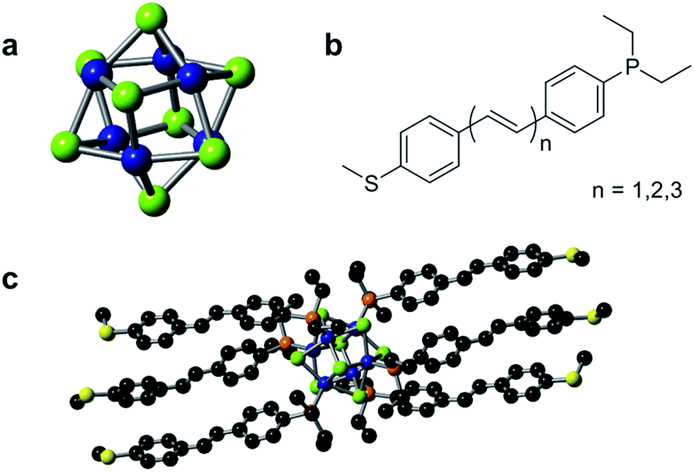 | ||
| Fig. 1 (a) Structure of the cluster core Co6Se8. (b) Chemical structure of the conducting ligand series Ln (n = 1, 2, 3). (c) Molecular structure of 1 as characterized by single crystal X-ray diffraction. Carbon, black; cobalt, blue; selenium, green; phosphorus, orange; sulfur, yellow. | ||
We measured the conductance of both the individual molecular clusters (1–3) and the free conducting ligands (L1–L3) using a scanning tunneling microscope-based break-junction (STM-BJ) technique.21 In this technique, an Au STM tip and substrate are repeatedly brought into and out of contact to form and break Au–Au point contacts in solutions of the target compounds. During this process, a bias voltage is applied across the junction while current is measured in order to determine conductance (G = I/V) of the junction. The measurements are repeated thousands of times, and the data is analyzed to reveal statistically significant results. The data is processed by compiling thousands of individual conductance traces into one-dimensional, logarithmically-binned conductance histograms.22 We further generate two-dimensional (2D) histograms of the conductance versus displacement by aligning each conductance trace after the point contact ruptures (at a conductance of 0.5 G0) and overlaying all conductance traces.
In order to characterize transport through the molecular clusters and the free ligands, we measured the conductance of 1–3 and L1–L3 in two different solvents, BrN and TCB. These solvents were chosen taking into consideration the solubility of both the ligand and the cluster systems as well as for their varied affinity to gold electrodes.23Fig. 2a and b contain the one-dimensional histograms for the measurements in BrN, and Fig. 2d and e show the same for the measurements in TCB. The 2D histograms for 1 and L1 in each solvent are insets in the respective figures. The 2D histograms show a significant difference in length of the molecular feature for 1 and for L1. Moreover, the cluster junction lengths measured from the 2D histograms correlate with the molecular lengths of the cluster with the ligands fully extended (measured in BrN: 9 Å and 21 Å, and expected from SCXRD: 13 Å and 32 Å, for L1 and 1 respectively). Despite the additional complexity of the cluster system, we conclude that we are indeed probing transport through Au–ligand–cluster–ligand–Au junctions based on this large difference in the observed lengths. Furthermore, the histograms in Fig. 2a and d show shoulders, with an increasing prominence for the longer-ligand systems. Comparing the conductance of these shoulders with the ligand conductance in Fig. 2b and e, we attribute these shoulders to free ligands, that is, ligands that have detached from the clusters.
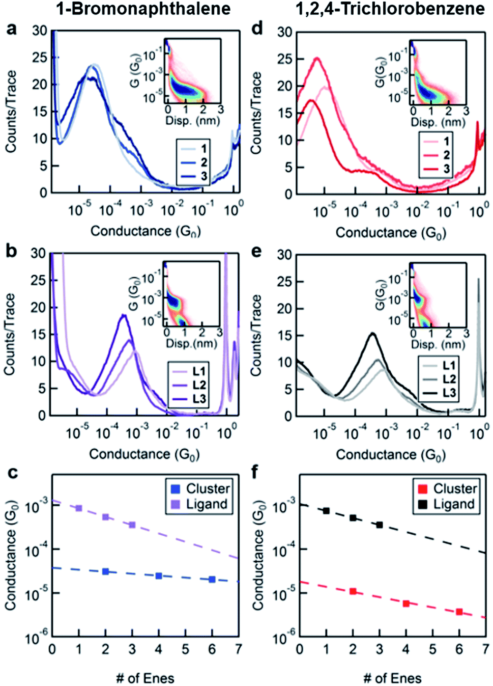 | ||
| Fig. 2 Logarithmically-binned conductance histograms for 1–3 in (a) BrN and (d) TCB and L1–L3 in (b) BrN and (e) TCB. Insets in (a) and (d) and (b) and (e) are 2D histograms for 1 and L1 respectively. (c) and (f) Conductance peak values of the single molecule junctions for 1–3 and L1–L3 as a function of total number of “ene” units (e.g., 1 has 2 units while L1 has 1 unit) for measurements in BrN and TCB, respectively shown on a semi-log plot along with least-square linear fits. Marker size reflects the error in the Gaussian fits to the conductance histogram peaks. | ||
We fit the peaks of all conductance histograms for both solvents with a Gaussian function and plot the peak conductance values versus the number of C![[double bond, length as m-dash]](https://www.rsc.org/images/entities/char_e001.gif) C units or “enes” in each molecule (Fig. 2c and f). In both solvents, and for both free ligand and cluster, we observe that the conductance decreases exponentially with increasing molecular length following the relationship G ∼ e−βn, where n is the number of “ene” units in the backbone and β is the decay constant. We report the decay constant per Angstrom using a length of 2.48 Å per “ene” unit. The decay constant for the free ligand series is essentially independent of the solvent (β = 0.15 Å−1 in TCB and 0.17 Å−1 BrN).
C units or “enes” in each molecule (Fig. 2c and f). In both solvents, and for both free ligand and cluster, we observe that the conductance decreases exponentially with increasing molecular length following the relationship G ∼ e−βn, where n is the number of “ene” units in the backbone and β is the decay constant. We report the decay constant per Angstrom using a length of 2.48 Å per “ene” unit. The decay constant for the free ligand series is essentially independent of the solvent (β = 0.15 Å−1 in TCB and 0.17 Å−1 BrN).
The unexpected result is the factor of 3 difference in the decay constants of the cluster series in different solvents as can be seen comparing Fig. 2c and f. In TCB, the β of the cluster system is 0.12 Å−1, and in BrN it is 0.04 Å−1. We note that the difference between the decay constant of the ligand and that of the cluster is greater in BrN than in TCB. Furthermore, the absolute values of the conductance of the cluster series are significantly higher when measured in BrN than in TCB, with the conductance of 3 being almost an order of magnitude higher in BrN compared to TCB. Such a solvent-induced effect on the conductance has been observed in other systems, and this has been attributed to the solvent's ability to modulate the electrode work function.23,24
These findings are summarized: regardless of solvent the effect of CC chain-length on conductance is less pronounced in 1–3 than in L1–L3. Furthermore, the conductance and the decay of L1–L3 are essentially insensitive to the choice of solvent, while the solvent significantly influences those of 1–3. To understand these results we consider several possible mechanisms of charge transport through these junctions. Charge transport can occur via a coherent off-resonance process through an orbital on the ligand–cluster–ligand assembly that is coupled to both electrodes. In that situation, the conductance depends on at least two related factors: (1) the energy of this conducting orbital relative to the metal EF, and (2) the coupling between this orbital and both electrodes.25 As the length of the molecule increases, the HOMO–LUMO gap narrows, and if conductance were just related to energy level alignment, one would naively expect conductance to actually increase. However, transport through the junction is also related to how well the conducting orbital overlaps with the leads, and since the orbital is more delocalized over a longer conjugated molecule, this overlap decreases with increasing length. The conductance thus typically decays exponentially with increasing molecular length. Specifically, as the conjugated backbone gets longer, the molecular orbital is delocalized over a longer molecule, and since the orbital is normalized, a smaller fraction of its amplitude resides on the sulfur atoms; therefore the coupling between the molecule and the electrodes decreases.
If we assume that the conducting orbitals of the cluster and of the ligand for a given length are similar in both character and energy, we can develop a simple tight-binding model of the molecular junctions. The objective of this model is not to reproduce the experimental data but to examine and illustrate how the additional electronic structure of the cluster impacts transport through the system. Our tight-binding model is schematically presented in the insets of Fig. 3a and b for the ligand and the cluster respectively. For the conducting ligands, we assign a single energy level, ε, for each unit, and allow nearest neighbors to be coupled by δ. The terminal units are coupled to the Au electrodes using an imaginary self-energy, iΓ/2. We apply a similar model for the cluster, adding an additional energy level, E0, between two ligands and coupling this site to its nearest neighbor ligand states with τ. We compute the transmission functions for these model systems using a Green's function approach (see the ESI for a detailed description†).25,26 Sample computed transmission functions are shown in Fig. 3a and b using the same values for ε, δ and Γ for the ligand and the cluster series. The transmission functions display resonances at energy values corresponding to the molecular orbitals of the system where the probability of an electron being transmitted through the system is unity. The transmission function for L1 contains one resonance at energy ε, while longer ligands have resonances equal to the number of sites in the corresponding model. As the length of the molecule increases, the frontier resonance moves closer to EF but also narrows, which is a consequence of the frontier orbital being delocalized over a longer molecular backbone. Upon comparing the transmission functions for the ligands with those of the clusters, we see that the clusters contain resonances that are closer to EF than their ligand counterparts, but with narrower full widths at half max (i.e. they are more poorly coupled to the leads). This observation leads to a lower transmission at EF; more importantly, it also leads to a conductance that is more sensitive to the exact location of the EF.
 | ||
| Fig. 3 Sample transmission functions using the tight-binding model for (a) ligand and (b) cluster series. Insets in (a) and (b) are schematic diagrams of the models used. Parameters employed are Γ = −0.15 eV, δ = −1.5 eV, ε = −3.5 eV, τ = −1 eV, and E0 = −1.9 eV. (c) Conductance values versus number of repeat ligand levels, taken from the transmission functions shown. The data points in (c) are color-coded as the transmission functions in (a) and (b). Data points are fit with a line, and both lines show a similar decay of about 0.5 Å−1. (d) 2D plot showing the ratio of decay constants βLigand/βCluster, obtained by keeping Γ, ε, and δ constant, while varying E0 and τ (the parameters for the cluster site). It is not possible to obtain a ligand decay constant that is more than 1.2 times that of the cluster decay constant. | ||
In Fig. 3c, we show the conductances that are determined from the tight-binding model for each molecule versus the number of ligand levels in the molecule (using the same model parameter values for both series). From the fit to these values, it is clear that the predicted decay constants are essentially the same for the ligand and cluster series. We use one set of E0 and τ values to calculate the representative transmission/conductance functions shown in Fig. 3a and b. Regardless of what value is assigned to E0 and τ, we find that this model predicts very similar decay constants for the two systems (Fig. 3d).
Our tight-binding calculations suggest that the addition of a cluster level E0 between two ligands cannot explain the observed change in β. In other words, the ligand and cluster series should have the same β values, unless the energy alignment of the cluster resonance is altered relative to the electrode Fermi level in this model. We have three sets of observations that are consistent with a change in EF: (1) β of the cluster in BrN is significantly lower than in TCB, (2) β values measured in both solvents are almost the same for the ligand series, and (3) β of the cluster is lower than that of the ligand in both solvents. The steeper transmission curves of the cluster series in Fig. 3 indicate that the resonance energies are closer to EF. Within this coherent transport model, we can see that a small change in EF will result in a large shift in β for the cluster relative to the ligand. For instance, changing EF by −0.5 eV shifts the β value to 0.1 Å−1 for the clusters while a similar change in EF for the ligand changes β to 0.3 Å−1. These results, when viewed in light of the known ability of solvent-binding to produce changes in EF,23 point to BrN shifting EF closer to resonance relative to TCB. This effect is compounded by the sensitivity of the metal. The free ligand and the cluster have very different characteristics (e.g., size, steric hindrance, redox behaviour, dielectric constant polarizability and binding ability) that will result in different shifts in EF.
We also consider a hopping mechanism for charge transfer, a process generally mediated by an activation-controlled reaction (e.g., a thermally induced conformational change or an electron transfer reaction).27,28 We first rule out the possibility that such a conformational change can occur within the ligand.3 We also refute the process involving a direct through-space charge transfer from the electrode to an unoccupied molecular level on the cluster through a resonant transfer process.14 In this picture, the cluster does not have to be chemically attached to the electrodes to form a conducting junction and the charge transfer efficiency depends on the core-electrode spacing. We discount this mechanism based on a previously published study in which we demonstrated that our clusters form molecular junctions by bonding their terminal thiomethyl groups to the Au electrodes.15 By varying the substitution pattern or removing the aurophilic functionality, we can modulate or completely shut down the conductivity of these molecular junctions, suggesting that there is an orbital pathway for the transport of charge in these cluster systems. These findings refute the idea of direct through-space charge transfer mediated by an orbital localized on the core.
We are left with a hopping mechanism in which the charge tunnels from the source electrode across the ligand to the cluster core and then transfers to the drain electrode through a second coherent tunneling process. Such a transport process requires that the cluster can reversibly change its oxidation state with each charge transfer. Since the applied bias in these measurements is not small (∼0.5 V) and the cluster core Co6Se8 is redox active, it is plausible that such a hopping process is at play. In this case, the activation energy arises from the charge transfer process reorganization energy, which can be strongly influenced by the solvent. This mechanism is consistent with our observation that β changes with solvent. Within our experimental constraints, it is therefore difficult to conclusively establish which process (off-resonance tunneling or hopping) is at work in our single cluster junction system.
Conclusions
In summary, we measured charge transport through molecular clusters with ligands of different lengths and showed that the conductance decay depends on the solvent used for these measurements. Our results illustrate a novel effect that allows the environment to alter the conductance decay constants. This study opens up the possibility to carry out conductance measurements in which clusters can be controllably gated by changing the environment.20 While the conducting ligands alone are limited to a one-dimensional system, the three-dimensional architecture of the metal chalcogenide cluster allows us to envision novel electronic devices where a molecular cluster is contacted by electrodes at multiple locations.Acknowledgements
We thank Dr. Hybertsen and Prof. Reichman for useful discussions. Support for this project was provided by the Office of Basic Energy Sciences, U.S. Department of Energy (DOE) under award number DE-FG02-01ER15264. The break-junction measurements were supported by the NSF under award DMR-1206202. This material is based upon work supported by the Air Force Office of Scientific Research under AFOSR Award No. FA9550-14-1-0381. Bonnie Choi thanks the NSF for a graduate research fellowship (DGE 11-44155). Giacomo Lovat acknowledges support from the Center for Precision Assembly of Superstratic and Superatomic Solids at Columbia University, an NSF MRSEC (award number DMR-1420634).References
- A. Nitzan and M. A. Ratner, Science, 2003, 300, 1384–1389 CrossRef PubMed.
- C. Joachim, J. K. Gimzewski and A. Aviram, Nature, 2000, 408, 541–548 CrossRef PubMed.
- J. S. Meisner, M. Kamenetska, M. Krikorian, M. L. Steigerwald, L. Venkataraman and C. Nuckolls, Nano Lett., 2011, 11, 1575–1579 CrossRef CAS PubMed.
- F. Chen, X. L. Li, J. Hihath, Z. F. Huang and N. J. Tao, J. Am. Chem. Soc., 2006, 128, 15874–15881 CrossRef CAS PubMed.
- X. L. Li, J. He, J. Hihath, B. Q. Xu, S. M. Lindsay and N. J. Tao, J. Am. Chem. Soc., 2006, 128, 2135–2141 CrossRef CAS PubMed.
- G. C. Solomon, D. Q. Andrews, T. Hansen, R. H. Goldsmith, M. R. Wasielewski, R. P. Van Duyne and M. A. Ratner, J. Chem. Phys., 2008, 129, 054701/1–054701/8 CrossRef CAS PubMed.
- L. E. Scullion, E. Leary, S. J. Higgins and R. J. Nichols, J. Phys. Condens. Matter, 2012, 24, 164211 CrossRef PubMed.
- C. S. Wang, A. S. Batsanov, M. R. Bryce, S. Martin, R. J. Nichols, S. J. Higgins, V. M. Garcia-Suarez and C. J. Lambert, J. Am. Chem. Soc., 2009, 131, 15647–15654 CrossRef CAS PubMed.
- S. Martin, I. Grace, M. R. Bryce, C. S. Wang, R. Jitchati, A. S. Batsanov, S. J. Higgins, C. J. Lambert and R. J. Nichols, J. Am. Chem. Soc., 2010, 132, 9157–9164 CrossRef CAS PubMed.
- R. Yamada, H. Kumazawa, T. Noutoshi, S. Tanaka and H. Tada, Nano Lett., 2008, 8, 1237–1240 CrossRef CAS PubMed.
- B. M. Boardman, J. R. Widawsky, Y. S. Park, C. L. Schenck, L. Venkataraman, M. L. Steigerwald and C. Nuckolls, J. Am. Chem. Soc., 2011, 133, 8455–8457 CrossRef CAS PubMed.
- T. Yelin, R. Vardimon, N. Kuritz, R. Korytar, A. Bagrets, F. Evers, L. Kronik and O. Tal, Nano Lett., 2013, 13, 1956–1961 CrossRef CAS PubMed.
- E. Leary, H. Van Zalinge, S. J. Higgins, R. J. Nichols, F. F. de Biani, P. Leoni, L. Marchetti and P. Zanello, Phys. Chem. Chem. Phys., 2009, 11, 5198–5202 RSC.
- J. Park, A. N. Pasupathy, J. I. Goldsmith, C. Chang, Y. Yaish, J. R. Petta, M. Rinkoski, J. P. Sethna, H. D. Abruna, P. L. McEuen and D. C. Ralph, Nature, 2002, 417, 722–725 CrossRef CAS PubMed.
- X. Roy, C. L. Schenck, S. Ahn, R. A. Lalancette, L. Venkataraman, C. Nuckolls and M. L. Steigerwald, Angew. Chem., Int. Ed., 2012, 51, 12473–12476 CrossRef CAS PubMed.
- S. M. Stuczynski, Y. U. Kwon and M. L. Steigerwald, J. Organomet. Chem., 1993, 449, 167–172 CrossRef CAS.
- N. R. M. Crawford, A. G. Hee and J. R. Long, J. Am. Chem. Soc., 2002, 124, 14842–14843 CrossRef CAS PubMed.
- J. S. Meisner, S. Ahn, S. V. Aradhya, M. Krikorian, R. Parameswaran, M. Steigerwald, L. Venkataraman and C. Nuckolls, J. Am. Chem. Soc., 2012, 134, 20440–20445 CrossRef CAS PubMed.
- Y. S. Park, A. C. Whalley, M. Kamenetska, M. L. Steigerwald, M. S. Hybertsen, C. Nuckolls and L. Venkataraman, J. Am. Chem. Soc., 2007, 129, 15768–15769 CrossRef CAS PubMed.
- C. R. Arroyo, E. Leary, A. Castellanos-Gomez, G. Rubio-Bollinger, M. T. Gonzalez and N. Agrait, J. Am. Chem. Soc., 2011, 133, 14313–14319 CrossRef CAS PubMed.
- B. Q. Xu and N. J. J. Tao, Science, 2003, 301, 1221–1223 CrossRef CAS PubMed.
- M. T. Gonzalez, S. M. Wu, R. Huber, S. J. van der Molen, C. Schonenberger and M. Calame, Nano Lett., 2006, 6, 2238–2242 CrossRef CAS PubMed.
- V. Fatemi, M. Kamenetska, J. B. Neaton and L. Venkataraman, Nano Lett., 2011, 11, 1988–1992 CrossRef CAS PubMed.
- S. Nakashima, Y. Takahashi and M. Kiguchi, Beilstein J. Nanotechnol., 2011, 2, 755–759 CrossRef CAS PubMed.
- S. Datta, Quantum Transport - Atom to Transistor, Cambridge University Press, 2005 Search PubMed.
- A. Nitzan, Annu. Rev. Phys. Chem., 2001, 52, 681–750 CrossRef CAS PubMed.
- S. H. Choi, B. Kim and C. D. Frisbie, Science, 2008, 320, 1482–1486 CrossRef CAS PubMed.
- We note that temperature dependent measurements using an STM-based break-junction experimental setup cannot distinguish a hopping mechanism from an off-resonant transport mechanism as simple molecules such as 1,4-diaminobenzene show a strong temperature dependent conductance. M. Kamenetska, Ph.D. Thesis, Columbia University, 2012.
Footnotes |
| † Electronic supplementary information (ESI) available: Synthetic details and characterization data for compounds 1–3, L1–L3; experimental and data analysis details; theoretical methods. See DOI: 10.1039/c5sc02595h |
| ‡ These authors contributed equally. |
| This journal is © The Royal Society of Chemistry 2016 |