Photonic contacting of gas–liquid phases in a falling film microreactor for continuous-flow photochemical catalysis with visible light†
Received
19th September 2016
, Accepted 26th September 2016
First published on 6th October 2016
Abstract
A microstructured falling film reactor was applied to the dye-sensitized photochemical conversion of 1,5-dihydroxynaphthalene to juglone. This continuous-flow microreactor enables the efficient contacting of a gas and a liquid phase in combination with external irradiation by high-power LED arrays offering various wavelengths. Two sensitizers were used for the photochemical in situ generation of singlet oxygen as key step in the synthesis of the natural product juglone. The photochemical process was investigated according LED wavelength, LED power, oxygen partial pressure, reactor architecture, substrate concentration and flow rate, and optimized to a conversion of X = 97% with 99% selectivity. Based on the experimental results process parameters like quantum efficiency, productivity and space time yield were calculated and used for the evaluation of the photochemically catalyzed synthesis of juglone in continuous-flow mode.
Introduction
Photochemically catalysed reactions have become of fundamental interest in the recent years.1–5 Especially with the advent of photocatalytically active compounds and materials, which are able to absorb light in the visible region of the electromagnetic spectrum, many new synthetic methods have been developed for the preparation of valuable fine chemicals under mild reaction conditions.6–15 A broad variety of transformations can be performed with organometallic compounds like Ru- or Ir-based polypyridyl complexes.16,17 In conjunction with organocatalysts as chiral inductors stereoselective synthesis has been made possible as well.18–22 More recently the application of precious metal-free catalysts has amplified the development of cost-efficient synthetic protocols for photochemical reactions.23–26 Meanwhile it has been generally accepted that light, i.e. photons with defined wavelength, is a highly potent, selective and, in terms of Green Chemistry, a traceless reagent for synthetic organic chemistry.27,28
The dye-sensitized activation of molecular oxygen offers an important strategy to incorporate oxygen into molecules under mild reaction conditions.29 A first industrial application of photochemical oxygen activation has made its way into production. The Sanofi process for the production of artemisinin is one important example for the in situ formation of singlet oxygen using tetraphenylporphyrine as visible light-absorbing sensitizer.30 Starting in 2013 the final production scale of 60 tons per year has already been reached in 2014. Two important prerequisites must be fulfilled in this case for a successful realization of dye-sensitized singlet oxygen formation: efficient oxygen gas contacting with the liquid phase and thorough irradiation of the reaction composition. In general, photochemical batch equipment, e.g. glass flasks and immersion-well setups with pressurized mercury lamps, often lack of efficient gas–liquid contacting and uniform irradiation of the reaction solution, possibly leading to prolonged irradiation and pronounced by-product formation.31,32 Pressurized mercury lamps are often used as light sources, although the emission of these high power lamps contains a considerable amount of UV light.33 Expensive filter equipment is necessary for the selection of defined emission bands as well as an efficient heat management for avoiding thermal reaction pathways.
Those limitations can be overcome by the application of continuously running microreactors and modern light emitting diodes (LEDs) making this combination a versatile tool for photochemical applications.34,35 Microstructured equipment is able to contact reagents in gas and/or liquid streams more efficiently due to a strongly increased surface to volume ratio.36–39 The reaction volume inside a microreactor is very small and suited for an excellent process control. Hot spot formation becomes manageable by exact temperature control leading often to improved conversion and selectivity in the reaction.40 Especially the irradiation of the reaction solution becomes easier. Thin film formation in microchannels or capillaries with a small inner diameter allows the full irradiation of the complete reaction volume inside the microchannels.41 The irradiation time can be exactly controlled by the flow rate of the reaction composition being pumped through the microstructures. These advantages offer many possibilities for improving in parallel the economic and the environmental sustainability of a chemical process.42 LEDs fundamentally enhanced the application range of photochemistry. Generating visible light of defined wavelength by low power consuming semiconductor materials has made LEDs to the light source of the future.43,44 LED technology necessitates neither filter equipment nor as intensive heat removal as it is the case for mercury lamps. LEDs are small-sized spot light emitters and are adaptable in arraying them according to the surface to be irradiated. These advantages make LEDs an ideal partner to continuously running microreactors.
Micro tubular-based reactors are an often used reactor type for continuous-flow photochemistry. Depending on the diameter of the tubular channel these reactors are used for process optimization on smallest scale (50–100 μL reactor volume) or for scale-up approaches under optimized conditions (up to hundreds of mL reactor volume). Takahashi et al. use a series of two small-sized glass reactors of 50 and 100 μl for the synthesis optimization of vitamin D3 from the provitamin D3via a combined photochemical and thermal synthesis route.45 Zeitler et al. performed a photocatalytic reductive dehalogenation in a glass microreactor of 100 μl reactor volume yielding a reaction time decrease from 12 h to 40 s compared to the batch synthesis.46 As one example for a small scale-up Ryu et al. connected two 8 mL glass-covered stainless-steel microchannel reactor in series for the synthesis of a key intermediate for myriceric acid A. Using Black light irradiation this set-up produced the desired compound on the gram-scale.47 Booker-Milburn et al. introduced a capillary photoreactor design in 2005 using a FEP capillary wrapped around an immersion well with a UV light source inside.48,49 Using capillaries with inner diameters of 3–4 mm allow large reactor volumes for scaling-up reactions without clogging. Photocycloadditions were transferred from batch to continuous-flow mode proving the superior productivity of the flow reactors on the multi-gram scale. This reactor concept was then used as model50 for a large number of custom-built flow reactors for purely liquid or gas–liquid reactions like C–H functionalization of tertiary arylamines,51 addition of glycosyl radicals into acrolein,52 azide reduction and bromination of alcohols,53 oxidative cyanation of amines,54 the Stadler–Ziegler synthesis for aromatic C–S bond formation,55 trifluoromethylation of heterocycles with gaseous ICF3,56 or photooxygenation during juglone synthesis.57 Tubular-based reactors enable segmented flow of gas and liquid slugs inside the channels or capillaries allowing efficient gas mass transfer into the liquid phase, while the reaction solution is fully illuminated. These conditions have been also used for the generation of singlet oxygen for the continuous-flow synthesis of artemisinin. Seeberger et al. modified and transferred the photooxygenation of dehydroartemisinic acid into flow mode.58,59 Recently, the process was enhanced by Rossen, Poliakoff and George with the sensitizer immobilized on a ion exchanger resin.60
Falling film reactors have been also applied to continuous-flow photochemistry. This type of reactors uses gravity to transport the reaction solution from the top of a glass barrel as thin film over the barrel's flat surface to its bottom. Griesbeck et al. combined this falling film reactor setup with a strong XeCl excimer lamp for irradiating the liquid film with UV light. A microstructured version of the falling film reactor was developed in order to decrease the liquid film thickness from millimetres to micrometres. The smaller thickness allows a strongly improved gas mass transfer into the liquid phase. Originally, the falling film microreactor (FFMR) was designed and successfully used as solvent evaporator and for highly exothermic reactions like hydrogenation of nitro groups.61–64 But its design (vide infra) also allows the selective irradiation of the reaction solution in its microstructure. Up to now the FFMR has been applied to three continuous-flow photochemical reactions: a) photochlorination of aromatic isocyanates,65 b) cycloaddition of singlet oxygen into cyclopentadien,66 and c) cycloaddition of singlet oxygen into 1,5-dihydroxynaphthalene for the synthesis of juglone.67
All reactions performed up to now lack of a detailed investigation of the process parameters of a continuous-flow photochemical reaction performed in the FFMR. To close this gap, we investigated the juglone synthesis as benchmark reaction performed in the FFMR with two sensitizers having different absorption wavelengths. The impact of the light source regarding the irradiation wavelength and the LED power are evaluated as well as the oxygen partial pressure and substrate concentration. Finally the architectural impact of the reactor will be evaluated as well. The quantum efficiency q, the productivity Lp and the space time yield STY are calculated for comparing the FFMR with other reactor types.
Results and discussion
Photomicroreactor and light sources
The FFMR is composed of a back plate carrying the heat exchanging unit and the inlet and outlet for the reaction solution (details can be found in Fig. S1 and S2 in the ESI†). It is followed by the reaction plate as the first key element of the reactor. On the front side of the reaction plate microchannels with different geometries for each plate have been incorporated by wet chemical etching (Table 1).
Table 1 Geometrical data of FFMR reaction plate microchannels
| Abbreviation |
Channel number N |
Width wch/μm |
Depth dch/μm |
Length lch/mm |
Irradiated length lirr ch/mm |
| FFMR_600 |
32 |
600 |
200 |
78 |
54 |
| FFMR_1200 |
16 |
1200 |
400 |
78 |
54 |
The reaction solution is fed through the top slit and pulled into the microchannels by gravity and capillary forces. Depending on the flow rate and viscosity of the solution thin films can be generated far below 100 μm. The reaction plate is fixed with a mask and sealing gasket followed by the top plate of the reactor housing. This last part contains the second key element of the reactor, an inspection window made of borosilicate glass (visible to irradiation: length lirr = 54 mm, width wirr = 29 mm, thickness: 12 mm). Due to the high transparency of borosilicate glass for visible light (90% for wavelengths of 370 nm ≤ λ ≤ 2000 nm)68 it is most suitable for irradiating the thin film on the reaction plate with external light sources. Beside the inspection window the top plate carries the inlet and outlet devices of the gas phase, which is typically fed from bottom to top of the reactor. This arrangement allows a counter current flow of the gas stream against the liquid flow resulting in an excellent gas liquid contacting and mass transfer.
LEDs were installed as energy efficient sources for irradiation. Violet, royal blue, green and cold-white LEDs (GeTian Opto-Electronics CO., LTD.) were used in order to allow the selective irradiation of different photocatalysts (Table 2, Fig. 4).
Table 2 Spectral parameters of LED
| LED |
Emission maximum λmax/nm |
FWHMa/nm |
|
Full width at half maximum of the spectral band.
|
| Violet |
410 |
22 |
| Royal blue |
455 |
24 |
| Green |
520 |
37 |
| Cold-white (blue part) |
442 (sharp) |
22 |
| Cold-white (red part) |
550 (broad) |
123 |
An aluminium body was designed as heat sink carrying two LEDs (Fig. 1). These LED arrays can be fixed magnetically in front of the inspection window of the FFMR allowing a quick exchange of the array maintaining the same light path properties for all LEDs used in this work. Due to the LED's wide angle of radiation of 120° the complete reaction plate inside the reactor was irradiated. Special attention was drawn on a light-proof design of the LED array due to two reasons. First, the use of high-power irradiation, especially close to the UV region, requires safety precautions for protecting the eyesight of the experimenter. Second, light-tightness is the prerequisite for the full availability of all photons produced by the LED array inside the reactor to be used for the photochemical reaction.
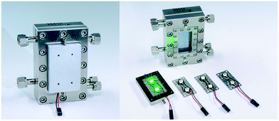 |
| | Fig. 1 Falling film microreactor with a magnetically attached heat sink carrying exchangeable LED arrays (©Fraunhofer ICT-IMM). | |
Lab plant design
The lab plant was equipped with standard components for the complete set of experiments (Fig. 2). A water-filled thermostat (Julabo F10 and HC E07) was used to maintain the temperature of the FFMR at 20 °C. Synthetic air or pure oxygen (Linde AG) was released from a pressurized steel cylinder and broad to 1 bar application pressure with an appropriate pressure regulator (Linde AG, FMD 300-18). The fine regulation of current and voltage for the LED arrays were done with a standard power supply (Basetech BT-305). Two piston pumps (Chemyx Inc., Nexus 5000) were used to feed and withdraw the liquid phase from the FFMR. The gas flow rate was regulated by a mechanical rotameter (Baley, Fisher & Porter, G10A6142DA131X100). A flow chart can be found in Scheme S1 in the ESI.†
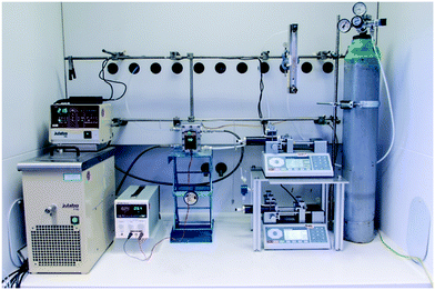 |
| | Fig. 2 Lab plant used for photochemical transformations with a falling film microreactor as core element. | |
For sample taking a device was implemented between the reactor outlet and the withdrawing pump using two needles inside a HPLC vial. The feeding needle was placed at the bottom of the vial, whereas the withdrawing needle was placed 12 mm above the vial's bottom. This arrangement allows the continuous filling of the HPLC vial during the process with a defined volume of reaction solution. For each HPLC sample a new vial was plugged onto the stationary mounted needles (see Fig. S3 in the ESI†). Details on the analytical HPLC method can be found on page S5 of the ESI.†
Benchmark reaction and sensitizers
The photooxygenation of DHN has been performed in several types of flow reactors so far. Beside classical immersion well reactors equipped with mercury pressure lamps also sunlight collecting and concentrating reactors were used for the continuous-flow synthesis of juglone,69–71 whereas microscale reactors like capillary reactors overcome insufficient irradiation.57,72
The key step in the photooxygenation of 1,5-dihydroxynaphthalene (DHN) to juglone is the in situ formation of singlet oxygen that pursues a [4 + 2] cycloaddition with DHN.73–75 The resulting endoperoxide is unstable and is instantaneously transformed to juglone and water (Fig. 3). Singlet oxygen can be produced under harsh chemical conditions76 (being often not compatible with the stability of substrate molecules) or via a mild photocatalytic process.77 The latter case needs a sensitizer like rose bengal (RB) or meso-tetraphenylporphyrine (TPP) exhibiting a triplet state energy greater than 95 kJ mol−1.78 After irradiation with light of appropriate wavelength the sensitizer is excited first to its singlet state which undergoes intersystem crossing (ISC) to the triplet state.78 With a triplet oxygen molecule in close vicinity to the sensitizer energy transfer is possible yielding the highly reactive singlet oxygen species.79 Although RB achieves a high quantum yield for singlet oxygen formation, it is known that this naturally occurring dye decomposes quite rapidly by photobleaching.80 In the case of TPP the triplet quantum yield is slightly lower, but the photostability of the dye is considerably higher.81
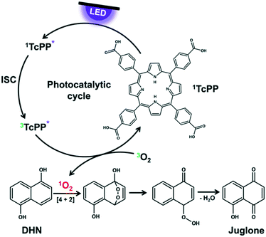 |
| | Fig. 3 Photocatalytic cycle of TcPP for singlet oxygen formation as key step in juglone synthesis. | |
To ensure comparability between the experiments both sensitizers are used under the same reaction conditions. RB is a salt which dissolves very good in aqueous solutions, but neither DHN nor TPP are soluble in water. In consequence, 2-propanol was chosen as environmental friendly solvent for all experiments.82 It has a cut-off wavelength of 240 nm ensuring that no interactions take place between the incident visible light and the reaction medium. The nonpolar TPP was substituted by its derivative meso-tetracarboxyphenylporphyrine (TcPP) containing four free carboxylic acids in para-position of the phenyl residues.83 Despite a small bathochromic shift of the Soret band, these functional groups do not disturb the UV/vis absorption properties of the monomeric porphyrine core in polar solutions, but enhance the solubility of the sensitizer for its use in the chosen solvent.84 Details on the Synthesis of TcPP can be found in the ESI† on page S6.
Definitions and control experiments
For a clear comparison of all experiments throughout this work a set of physical and chemical reaction parameters were defined (Table 3). Variations of these parameters due to a detailed investigation of their impact on the photocatalytic process are mentioned accordingly.
Table 3 Defined standard solution and standard reaction conditions for the continuous-flow synthesis of juglone in a FFMR
| Parameter |
Value |
| Substrate concentration cDHN |
10 × 10−3 mol L−1 |
| Sensitizer concentration csens |
0.5 × 10⁻³ mol L−1 |
| Solvent |
2-Propanol |
| Liquid flow rate fl |
0.16 mL min−1 |
| Gas flow rate fg |
100 mL min−1 |
| Reactor temperature TFFMR |
20 °C |
| Reactor pressure pFFMR |
Atmospheric pressure |
| LED array amperage ILED |
350 mA |
The main parameters varied in this work are the type of sensitizer (rose bengal or TcPP) and the light source (green, royal blue, violet, and cold-white). For an easier description of the reaction conditions the following sensitizer-light source combinations are abbreviated as defined in Table 4.
Table 4 Abbreviations of sensitizer-light source combinations used in this work
| Sensitizer |
Light source |
Abbreviation |
| Rose bengal |
Cold-white |
RB-cw |
| Violet |
RB-v |
| Royal blue |
RB-b |
| Green |
RB-g |
|
meso-Tetracarboxy-phenylporphyrine |
Cold-white |
TcPP-cw |
| Violet |
TcPP-v |
| Royal blue |
TcPP-b |
| Green |
TcPP-g |
A control experiment has been performed in order to assess the necessity of a sensitizer for a successful realization of the juglone synthesis. A standard solution without sensitizer was used under standard conditions with a cold-white LED providing the broadest emission range. As expected no conversion to juglone was observed due to the absence of singlet oxygen solely produced by an appropriate sensitizer. Beside this prove any photochemical decomposition pathways of the starting material could be ruled out as seen by the HPLC analysis. Further control experiments were performed in order to assess the photochemical decomposition of juglone during the irradiation. Compared to DHN juglone absorbs light in the visible spectrum which might lead to consecutive reactions (for the UV/vis absorption spectra, see Fig. S6 in the ESI†). Commercially available juglone was used as starting material in the standard solution instead of DHN. Four experiments were performed with RB-cw, RB-g, TcPP-cw and TcPP-v under standard conditions. HPLC analysis confirmed that no decomposition of juglone or any follow-up reactions occurred in these experiments.
Influence of light source on sensitizer excitation
As first parameter the emission wavelength was evaluated for both sensitizers with pure oxygen on a FFMR_1200 plate under standard conditions. RB and TcPP have a specific UV/vis absorption pattern which result in unique emission–absorption overlaps for each LED array (Fig. 4). Each overlap is representative for the excitation of the sensitizers and in consequence for the singlet oxygen formation.
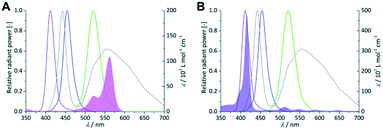 |
| | Fig. 4 Coloured lines indicate the spectral emission bands of the violet, royal blue, green and cold-white LEDs (left Y-axis = relative radiant power). UV/vis absorption spectra of 0.25 × 10⁻³ mol L−1 RB (A; pink area) and 1 × 10⁻⁶ mol L−1 TcPP (B; violet area) in 2-propanol (right Y-axis = molar extinction coefficient). | |
In the case of RB the gradual increase in conversion correlates with the increasing overlap of light emission and dye absorption. The best yields were obtained for the cold-white and the green LED (Fig. 5). The broad emission of the cold-white LED covers the whole absorption band of RB in the visible region between 470 nm and 600 nm. Its peak emission is in perfect overlap with the maximum absorption of RB at 550 nm. The green LED emission spectrum overlaps only in part with the RB absorption, particularly in the low absorbing region between 470 nm and 550 nm. The small overlap in RB-v and RB-b is clearly confirmed by the low conversion of 9% and 15%, respectively. Concerning the product selectivity, RB-g achieved the highest selectivity of S = 93%, whereas RB-cw reached a slightly lower selectivity of S = 87%. Although RB-cw results in higher conversion compared to RB-g it was decided to the favour the higher selectivity with RB-g for further experiments.
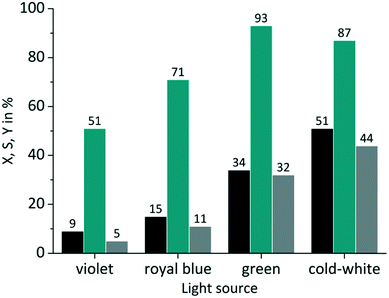 |
| | Fig. 5 Impact of emission wavelength on conversion and selectivity in juglone synthesis with RB and oxygen on a FFMR_1200 plate (■ conversion X;  selectivity S; selectivity S;  yield Y). yield Y). | |
The same experiments were performed with TcPP (Fig. 6), which exhibits a split visible light absorption pattern with the Soret band (εmax = 416 nm) and the Q bands (εmax = 511, 547, 589, 646 nm). As it was the case for RB-g and RB-cw the best spectral overlap gives the highest conversion. TcPP-v achieves a conversion of X = 76%. The excellent overlap of the violet emission band with the strongly absorbing Soret band of the porphyrin core strongly contributes to high conversions for TcPP-v. Due to a shift to lower wavelengths and in consequence due to a less good spectral overlap TcPP-b only achieves a conversion of X = 18%. In the case of TcPP-g the green light emission shows a very good overlap with the Q bands of the porphyrin core resulting in a conversion of X = 19%. The emission of the cold-white LED allows a small overlap with the strongly absorbing Soret band and a very good overlap with the Q bands of the porphyrin core. This combination results for TcPP-cw in a conversion of X = 26%. Interestingly TcPP allows achieving higher selectivity than RB reaching nearly 100% for TcPP-v and TcPP-cw, 88% for TcPP-g and 78% for TcPP-b.
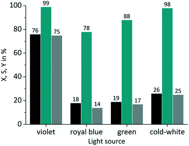 |
| | Fig. 6 Impact of emission wavelength on conversion and selectivity in juglone synthesis with TcPP and oxygen on a FFMR_1200 plate (■ conversion X;  selectivity S; selectivity S;  yield Y). yield Y). | |
Influence of LED power
In close conjunction to the first parameter the impact of the light power was evaluated in a second set of experiments. The amperage ILED of the LED arrays was varied from 175 mA over 350 mA (standard value) to 530 mA. These values correspond to a power Pel of 1.1 W, 2.38 W and 3.6 W respectively for the green LED array used in the tests. RB was applied on a FFMR_1200 plate under standard conditions with oxygen gas (Fig. 7).
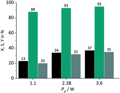 |
| | Fig. 7 Impact of light power on conversion and selectivity in juglone synthesis with RB and oxygen on a FFMR_1200 plate (■ conversion X;  selectivity S; selectivity S;  yield Y). yield Y). | |
The variation of the power has an impact on both the conversion and the selectivity. The increase in conversion can be attributed to the larger number of photons available with increasing power for singlet oxygen formation. Selectivity changed less strongly with increasing LED power, but with the same trend to higher values. In the case of switching the electrical power from 1.1 W to 2.38 W a relative increase in conversion of 48% and selectivity of 6% is given. The increase of electrical power from 2.38 W to 3.6 W (approx. 51%) results in a relative increase of only 9% and 2% for conversion and selectivity. These rather small differences are an important result for the optimisation of the photochemical process regarding its energy consumption. The low increase in conversion points to the fact that the larger number of available photons at 3.6 W are not used for the photochemical process.
Influence of oxygen partial pressure
The availability of dissolved oxygen is an important key factor for the singlet oxygen formation during the juglone synthesis. The solubility of oxygen in 2-propanol is given as its molar fraction with a value of 7.88 × 10⁻⁴ mol mol−1 at 20 °C and 1.013 bar.85 Applying Henry's law results under these conditions in an oxygen concentration O2coxygen = 10 × 10−3 mol L−1 (see Fig. S7 in the ESI†). The impact of the dissolved oxygen concentration was examined by the application of either pure oxygen (O2poxygen = 1.013 bar) or synthetic air with a fivefold lower oxygen content (aircoxygen = 2 × 10⁻³ mol L−1; airpoxygen = 0.202 bar). RB was used as sensitizer on a FFMR_1200 plate under standard conditions. As can be seen in Fig. 8 the use of synthetic air has only a small negative impact on the conversion rate compared to pure oxygen. The slightly decreased conversion for RB-g by 2% and for RB-cw by 7% can be attributed to a lower oxygen concentration in the liquid phase due to the decreased oxygen partial pressure in the synthetic air gas phase. But in general the photochemical process does not seem to be mass transfer limited by the oxygen gas phase.
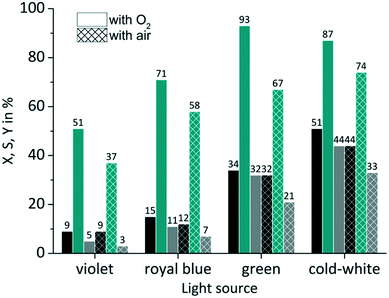 |
| | Fig. 8 Impact of oxygen partial pressure on conversion and selectivity in juglone synthesis with RB on a FFMR_1200 plate (■ conversion X;  selectivity S; selectivity S;  yield Y). yield Y). | |
In the case of selectivity the use of synthetic air has a far more negative impact. Especially with RB-g the selectivity drops by 26%. In all other cases the selectivity decreases by a value of approx. 13%. One reason for this moderate selectivity might be a competing reaction that involves the sensitized conversion of the endoperoxide intermediate. Bicyclic endoperoxides are known to be cleaved by appropriate irradiation resulting in oxygen radicals.86 These radicals can react intramolecularly with a double bond yielding epoxides.87 The existence of a sensitizer can promote this reaction,88 if the sensitizer is not quenched upfront by another reaction pathway like the singlet oxygen formation (see Scheme S2 in the ESI†). Due to the absence of excess oxygen in synthetic air RB might promote this competing reaction which is less pronounced in an oxygen-rich solution.
Influence of reaction plate architecture
The FFMR design comprises different reaction plate architectures (Table 1). As known from literature each channel geometry can result in different thin film geometry.89 Variations in thin film thickness have an impact on the gas–liquid phase contacting behaviour and in consequence on the conversion and selectivity of the examined reaction. The thin film formation can be investigated with a confocal laser microscope.38,90,91 With this method the experimental comparison of uncoated FFMR_600 with FFMR_1200 plates gave at the same flow rate a greater film thickness for the FFMR_600 than for the FFMR_1200 plate. A greater film thickness results in a longer residence time at the same flow rate applied for both plates offering the same channel area (Achannels = 1497.6 mm2). This point is reflected by the results obtained in this experiment. For TcPP-v and RB-g a relative increase in conversion of 15% and 25%, respectively, is obtained using the plate with the smaller channel architecture (FFMR_600) providing a greater film thickness and a longer residence time (Fig. 9). Selectivity increases as well, but not as consistent as for the conversion. These results indicate that a longer residence time is beneficial for the photochemical conversion.
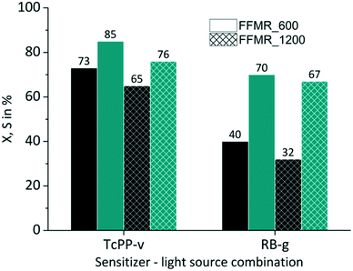 |
| | Fig. 9 Impact of plate architecture on conversion and selectivity in juglone synthesis with TcPP-v and RB-g with air (■ conversion X;  selectivity S). selectivity S). | |
Influence of substrate inlet concentration
Three DHN inlet concentrations were evaluated (5, 10, 20 × 10−3 mol L−1) keeping the amount of sensitizer constant at 5 × 10⁻⁴ mol L−1. All experiments were performed with synthetic air as oxygen source. For both RB-g and TcPP-v the conversion decreases with increasing DHN concentration (Fig. 10). This trend can be attributed to the higher relative amount of sensitizer and oxygen at lower substrate concentration.
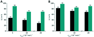 |
| | Fig. 10 Impact of DHN inlet concentration on conversion and selectivity in juglone synthesis with (A) RB-g and (B) TcPP-v on a FFMR_600 plate with air (■ conversion X;  selectivity S). selectivity S). | |
With increasing DHN concentration the values for the selectivity seem to run into a plateau with approx. S = 70% for RB-g and S = 88% for TcPP-v. The higher selectivity for the lowest DHN concentration may result also from the competing reaction pathways between singlet oxygen formation and sensitized endoperoxide conversion. The more sensitizer and oxygen are available for singlet oxygen formation the less pronounced is the endoperoxide side reaction.
Optimization of reaction parameters
With the experimental results obtained so far the best combination was used for optimization. This was the case for TcPP-v with oxygen gas on a FFMR_600 plate under standard conditions (X = 94%, S = 99%). This arrangement was used for applying different LED power (Fig. 11A) and liquid flow rates (Fig. 11B). In the first case a lower LED power resulted in a significant relative loss in conversion of 25%, whereas with a higher LED power the selectivity decreased by 6% close to full conversion. Hence, the tests with varying flow rates were performed with the medium LED power corresponding to Pel = 2.45 W. As expected, with the lowest flow rate of fl = 0.12 mL min−1 the highest conversion was achieved yielding X = 97% with S = 99%. With increasing flow rate the conversion decreased steadily to X = 65% at fl = 0.44 mL min−1 maintaining an excellent selectivity of S = 99%.
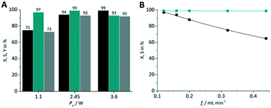 |
| | Fig. 11 Impact of (A) LED power and (B) flow rate on conversion and selectivity in juglone synthesis with TcPP-v on a FFMR_600 plate and oxygen (■ conversion X;  selectivity S, selectivity S,  yield Y). yield Y). | |
Theoretical part
In this section the correlation between the hydrodynamic behaviour of the reactor and the irradiation by the external LED arrays are presented and discussed for the experimental results with TcPP-v and RB-g. This section is split into two parts. In the first part the hydrodynamic and general parameters of the FFMR and the LED arrays are mathematically described and presented. The thickness of the liquid thin film inside the microchannels of the reaction plate is calculated as the main hydrodynamic parameter. The literature-known Nusselt eqn (1) allows a good approximation of the thin film thickness δ in the microchannels:92–94| |  | (1) |
with fl as the liquid flow rate (0.16 mL min−1), μl as the dynamic viscosity of 2-propanol at 20 °C (2.3 × 10⁻³ kg m−1 s−1), ρl as the density of 2-propanol at 20 °C (0.786 g mL−1) and g as the gravitational constant (0.981 m s−1). The parameters N and wch describe the number of microchannels and their width.95 With eqn (2) the liquid phase volume Virr inside the irradiated part of the microchannels can be calculated, the appropriate residence time τ with eqn (3):| |  | (2) |
| |  | (3) |
Under standard reaction conditions the thickness of the liquid film is approx. 50 μm with a mean residence time of 19.4 s inside the irradiated microchannels. Based on the dimension of the inspection window of the FFMR the irradiated surface on the reaction plate inside the reactor can be calculated with eqn (4), whereas the irradiated surface of the microchannels can be calculated with eqn (5):95
| |  | (4) |
| |  | (5) |
The irradiated microchannel area is with 1037 mm2 approx. 65% of the entire irradiated area since the embossments between the microchannels are not wetted with the liquid phase. Table 5 summarizes the results of the calculation for the hydrodynamic parameters for the FFMR including the general parameters for the irradiated surfaces inside the microreactor.
Table 5 Hydrodynamic and general parameters for the FFMR
| Thin film thickness δ |
50 μm |
| Irradiated volume Virr |
0.052 mL |
| Residence time τ |
19.4 s |
| Irradiated area in FFMR Airr |
1599 mm2 |
| Irradiated area in microchannels Airr ch |
1037 mm2 |
In the case of the LED arrays the radiant power PLED of the array is either given in the technical data sheet or can be calculated with this data.96,97 The luminescent efficiency ηlum of the LEDs can be calculated with eqn (6):
| |  | (6) |
with
Pel as the electrical power of the LED array at a current
ILED of 350 mA. With a transmission
T = 0.9 for the borosilicate glass of the inspection window the radiant power available inside the FFMR can be calculated as well (
eqn (7)):
68| |  | (7) |
Table 6 summarizes the results of the calculation for the general parameters for the LED arrays used with the FFMR.
Table 6 Available radiant power and luminescent efficiency of each LED array
|
|
Violet LED |
Green LED |
| Voltage ULED at 350 mA |
7 V |
6.8 V |
| Electrical power Pel |
2.45 W |
2.38 W |
| Radiant power PLED |
0.84 W |
0.37 W |
| Luminescent efficiency ηlum |
34.3% |
15.6% |
| Available radiant power Pav LED |
0.76 W |
0.34 W |
In the second part the photophysical parameters of the incident light and its interaction with the photocatalyst are mathematically described and presented (details and numbers of the calculation can be found on page S10 and S11 of the ESI†).31,98 It has to be noted that the following equations and calculations reflect an idealized process in which the incident light trespasses the thin film just once. Any scattering effects or reflections from the reactor chamber walls resulting in multiple light transits through the solution are not considered.99 The relative radiant power Prel λ of the LED arrays was extracted for each wavelength from the technical data sheet of the LED manufacturer. The decadic molar extinction coefficient was obtained from the UV/vis absorption spectra of both dyes. The density function of the light source gλ given by eqn (8) is defined as normalization factor for the calculation of the entire radiant power φλ per wavelength in eqn (9):
| |  | (8) |
| |  | (9) |
The available radiant power per wavelength in the microchannels φλ ch is defined by the ratio of the entirely irradiated surface to the irradiated surface of the microchannels (eqn (10)):
| |  | (10) |
Based on the experimentally obtained decadic molar extinction coefficient ελ the Napierian extinction coefficient μλ can be calculated for each wavelength (eqn (11)):
| |  | (11) |
Eqn (10) and (11) can be used on base of the Lambert–Beer law for the calculation of the radiant power per wavelength absorbed by the sensitizer in the liquid thin film φabs λ (eqn 12):
| |  | (12) |
With eqn (13) the photon absorption efficiency per wavelength ηphoton abs λ can be expressed by the ratio between the absorbed radiant power and the available radiant power per wavelength on the structured surface:
| |  | (13) |
The results from eqn (10) and (12) can now be converted into the molar amount of available photons (eqn (14)) and molar amount of absorbed photons absorbed by the sensitizer per wavelength during residence time τ (eqn (15)):
| |  | (14) |
| |  | (15) |
with
λ as the specific wavelength,
h as the Planck constant,
c for the speed of light and
NA as the Avogadro constant. The results of
eqn (10),
(12),
(14) and
(15) represent the available and absorbed power and the molar amount of available and absorbed photons, respectively, for each wavelength. With
eqn (16)–(19) these values are summarized in order to address the whole spectral emission and absorption range of the appropriate light source and sensitizer combination:
| |  | (16) |
| |  | (17) |
| |  | (18) |
| |  | (19) |
The energy efficiency ηE can be described as the ratio between the absorbed power φabs against the electrical power Pel (eqn (20)):
| |  | (20) |
Averaging the photon absorption efficiency over all wavelengths gives the mean photon absorption efficiency for the whole process (eqn (21)):
| |  | (21) |
The calculated result shows that TcPP-v is more efficient in the energy conversion as well as in the photon absorption with ηE = 0.13 and ![[small eta, Greek, macron]](https://www.rsc.org/images/entities/i_char_e0c8.gif) photon abs = 0.29 compared to ηE = 0.014 and
photon abs = 0.29 compared to ηE = 0.014 and ![[small eta, Greek, macron]](https://www.rsc.org/images/entities/i_char_e0c8.gif) photon abs = 0.19 for RB-g. The stronger efficiency of TcPP-v can be attributed to the better overlap of the main emission band of the LED array and the absorption band of the porphyrine sensitizer. One has also to keep in mind that both sensitizers have been used with the same molar concentration of 5 × 10⁻⁴ mol L−1 whereas the sensitizers differ in their extinction coefficients at their particular maximum absorption wavelength by a factor of approx. 4.7 (416εTcPP = 476
photon abs = 0.19 for RB-g. The stronger efficiency of TcPP-v can be attributed to the better overlap of the main emission band of the LED array and the absorption band of the porphyrine sensitizer. One has also to keep in mind that both sensitizers have been used with the same molar concentration of 5 × 10⁻⁴ mol L−1 whereas the sensitizers differ in their extinction coefficients at their particular maximum absorption wavelength by a factor of approx. 4.7 (416εTcPP = 476![[thin space (1/6-em)]](https://www.rsc.org/images/entities/char_2009.gif) 846 M−1 cm−1vs.562εRB = 109
846 M−1 cm−1vs.562εRB = 109![[thin space (1/6-em)]](https://www.rsc.org/images/entities/char_2009.gif) 410 M−1 cm−1). Table 7 summarizes the results of the theoretical evaluation for TcPP-v and RB-g.
410 M−1 cm−1). Table 7 summarizes the results of the theoretical evaluation for TcPP-v and RB-g.
Table 7 Calculated results for the absorption of available power and photons under standard reaction conditions
|
|
TcPP-v |
RB-g |
| Available power φch |
0.49 W |
0.217 W |
| Absorbed power φabs |
0.319 W |
0.034 W |
| Energy efficiency ηE |
0.13 |
0.014 |
Mean photon absorption efficiency ![[small eta, Greek, macron]](https://www.rsc.org/images/entities/i_char_e0c8.gif) photon abs photon abs |
0.29 |
0.19 |
| Molar amount of available photons nphotons ch τ |
3.3 × 10⁻⁵ mol |
1.8 × 10⁻⁵ mol |
| Molar amount of absorbed photons nabs photons τ |
2.1 × 10⁻⁵ mol |
2.9 × 10⁻⁶ mol |
The quantum efficiency q, the productivity Lp and the space time yield STY represent three important parameters for comparing a (photochemical-) process, which has been performed in different reactor types. The quantum efficiency q can be calculated with eqn (22)via the ratio of the molar amount of juglone produced during the residence time against the molar amount of photons absorbed by the sensitizer:
| |  | (22) |
The productivity Lp represents the molar quantity of juglone produced per unit of time (eqn (23)):
| |  | (23) |
The space time yield STY normalizes the productivity of the process to the liquid volume in the reactor (eqn (24)):
| |  | (24) |
All three parameters have been calculated for TcPP-v and RB-g used under standard reaction conditions with air on a FFMR_600 reaction plate and for TcPP-v also with oxygen gas (Table 8). In corollary to the efficiency results discussed above TcPP-v shows higher quantum efficiency than RB-g (Table 8, entry 1). Especially with oxygen gas TcPP-v shows an approx. 1.8 times higher quantum efficiency than RB-g. The same trend can be seen for the productivity Lp and the STY: RB-g/air < TcPP-v/air < Tcpp-v/oxygen (Table 8, entry 3–6).
Table 8 Quantum efficiency q, productivity Lp and STY for the processes with TcPP-v and RB-g under standard reaction conditions
| Entry |
|
TcPP-v |
RB-g |
| 1 |
Quantum eff. q (air) |
0.0095 |
0.008 |
| 2 |
Quantum eff. q (O2) |
0.014 |
— |
| 3 |
Productivity Lp (air) |
0.06 mmol h−1 |
0.03 mmol h−1 |
| 4 |
Productivity Lp (O2) |
0.09 mmol h−1 |
— |
| 5 |
STY (air) |
0.32 mol s−1 m−3 |
0.14 mol s−1 m−3 |
| 6 |
STY (O2) |
0.48 mol s−1 m−3 |
— |
These results can be compared with literature data from Oelgemöller et al. for the FFMR67 and from de Oliveira et al. for a capillary reactor57 using eqn (23) and (24) (Table 9). For better comparability only results were used which were obtained with white light sources. In the case of the FFMR processes it can be clearly seen that Lp and STY have been increased by a factor of up to 21 solely due to an improved light source architecture in our system (Table 9, entry 1–4). Furthermore, the capillary reactor can be seen as scale-up approach to the FFMR. A 37-fold increase in productivity (Table 9, entry 5) shows the strong impact of the different reactor architecture with larger reactor volume (25 mL) and higher liquid flow rate (0.75 mL min−1).100 In reverse, the STY of the FFMR is approx. 7 times higher than for the capillary reactor. Comparing the productivity of the capillary reactor with our optimized process in the FFMR using TcPP-v (Table 8, entry 4) instead of TcPP-cw (Table 9, entry 5) diminishes the factor of 37 to 8 for the productivity increase. This clearly indicates that an even higher productivity would be possible for the capillary reactor, if its light source would be optimized to the sensitizer, i.e. by using violet light for covering the Soret band of the porphyrin.
Table 9 Comparison of productivity Lp and STY for various combinations of sensitizers, white light sources and reactor types with cDHN = 10 mM, RB with air and TcPP/TPP with oxygen gas
| Entry |
|
|
This work FFMR_1200 |
Lit. [67] FFMR_1200 |
Lit. [57] capillary reactor |
|
RB & TcPP concentration was 0.5 mM.
TPP concentration was 0.03 mM.
CFL = compact fluorescence lamp.
|
|
|
Sens. |
|
RBa |
RBa |
|
| 1 |
LED |
L
p [mmol h−1] |
0.03 |
0.0015 |
— |
| 2 |
STY [mol s−1 m−3] |
0.17 |
0.008 |
|
| 3 |
CFLc |
L
p [mmol h−1] |
— |
0.006 |
— |
| 4 |
STY [mol s−1 m−3] |
0.04 |
|
|
Sens. |
|
TcPPa |
|
TPPb |
| 5 |
LED |
L
p [mmol h−1] |
0.02 |
— |
0.74 |
| 6 |
STY [mol s−1 m−3] |
0.13 |
0.02 |
Conclusions
With the results of this work we present a detailed investigation of the utilization of a microstructured falling film reactor for a photochemical application with visible light. The excellent capability of the FFMR to contact gas and liquid phases is combined with high-power LED arrays for the photonic contacting of the liquid phase that contains the metal-free sensitizers. With this setup singlet oxygen is produced in situ for the photochemically catalysed oxygenation of 1,5-dihydroxynaphthalene to juglone. Detailed investigations were performed according the light source, radiant power, oxygen partial pressure, reaction plate architecture, and substrate concentration. After optimization of the reaction conditions a conversion rate as high as 97% at 99% selectivity was achieved for the porphyrine sensitizer irradiated with violet light under pure oxygen gas atmosphere. The photochemical process in the FFMR was also theoretically investigated. It could be shown that the quantum efficiency can be improved by chemical reaction optimization, e.g. switch to pure oxygen gas, and physicochemical optimization, with e.g. a good spectral overlap of the emission and absorption bands of the chosen photocatalyst and LED array. Productivity and space time yield were compared with literature data showing that both parameters can be increased dramatically with specific adaptation of the light source to the reactor. Based on these results ongoing research activities investigate the variance in selectivity depending on the sensitizer-light source combination. Scale-up approaches and a more detailed observation of the irradiation characteristics inside the reactor chamber will be performed for a deeper understanding of the impact of scattering and reflection effects on the photochemical process in continuous-flow. This might allow in future an ecologically optimized combination of thin film thickness and full absorption of incident light at the main absorption wavelength of the sensitizer used.
Acknowledgements
T. H. R. wants to thank Dipl. Chem. Martin Poeschel (Johannes Gutenberg University Mainz), Dr. Anca Bogdan and Monika Balon-Burger (both Fraunhofer ICT-IMM) for their initial cowork in this research field. The authors want to thank Dr. Dirk Ziegenbalg (University of Stuttgart) for his helpful contributions and discussions.
Notes and references
- J. Barber, Chem. Soc. Rev., 2009, 38, 185 RSC.
- D. Ravelli, D. Dondi, M. Fagnoni and A. Albini, Chem. Soc. Rev., 2009, 38, 1999 RSC.
- D. Nocera, Acc. Chem. Res., 2012, 45, 767 CrossRef CAS PubMed.
- P. Frischmann, K. Mahata and F. Würthner, Chem. Soc. Rev., 2013, 42, 1847 RSC.
- R. Brimioulle, D. Lenhart, M. Maturi and T. Bach, Angew. Chem., Int. Ed., 2015, 54, 3872 CrossRef CAS PubMed.
- T. Yoon, M. Ischay and J. Du, Nat. Chem., 2010, 2, 527 CrossRef CAS PubMed.
- J. Xuan and W.-J. Xiao, Angew. Chem., Int. Ed., 2012, 51, 6828 CrossRef CAS PubMed.
- H. Kisch, Angew. Chem., Int. Ed., 2013, 52, 812 CrossRef CAS PubMed.
- J. Hu, J. Wang, T. Nguyen and N. Zheng, Beilstein J. Org. Chem., 2013, 9, 1977 CrossRef PubMed.
- D. Hari and B. König, Chem. Commun., 2014, 50, 6688 RSC.
- Q.-Q. Yang, M. Marchini, W.-J. Xiao, P. Ceroni and M. Bandini, Chem. – Eur. J., 2015, 50, 18052 CrossRef PubMed.
- J. Xuan, Z.-G. Zhang and W.-J. Xiao, Angew. Chem., Int. Ed., 2015, 54, 15632 CrossRef CAS PubMed.
- X. Lang, W. Hao, W. Leow, S. Li, J. Zhao and X. Chen, Chem. Sci., 2015, 6, 5000 RSC.
- M. Majek and A. von Wangelin, Angew. Chem., Int. Ed., 2015, 54, 2270 CrossRef CAS PubMed.
- H. Wang, L. Zhang, Z. Chen, J. Hu, S. Li, Z. Wang, J. Liu and X. Wang, Chem. Soc. Rev., 2014, 43, 5234 RSC.
- C. Prier, D. Rankic and D. MacMillan, Chem. Rev., 2013, 113, 5322 CrossRef CAS PubMed.
- A. Condie, J. González-Gómez and C. Stephenson, J. Am. Chem. Soc., 2010, 132, 1464 CrossRef CAS PubMed.
- M. Cherevatskaya, M. Neumann, S. Füldner, C. Harlander, S. Kümmel, S. Dankesreiter, A. Pfitzner, K. Zeitler and B. König, Angew. Chem., Int. Ed., 2012, 52, 4062 CrossRef PubMed.
- D. Ravelli, M. Fagnoni and A. Albini, Chem. Soc. Rev., 2013, 42, 97 RSC.
- M. Hopkinson, B. Sahoo, J.-L. Li and F. Glorius, Chem. – Eur. J., 2014, 20, 3874 CrossRef CAS PubMed.
- P. Riente, A. Adams, J. Albero, E. Palomares and M. Pericàs, Angew. Chem., Int. Ed., 2014, 53, 9613 CrossRef CAS PubMed.
- H. Huo, X. Shen, C. Wang, L. Zhang, P. Röse, L.-A. Chen, K. Harms, M. Marsch, G. Hilt and E. Meggers, Nature, 2014, 515, 100 CrossRef CAS PubMed.
- H. Sundén, M. Enqvist, J. Casas, I. Ibrahem and A. Córdova, Angew. Chem., Int. Ed., 2004, 43, 6532 CrossRef PubMed.
- M. Neumann, S. Füldner, B. König and K. Zeitler, Angew. Chem., Int. Ed., 2011, 50, 951 CrossRef CAS PubMed.
- Q. Liu, Y.-N. Li, H.-H. Zhang, B. Chen, C.-H. Tung and L.-Z. Wu, Chem. – Eur. J., 2012, 18, 620 CrossRef CAS PubMed.
- I. Gosh, T. Gosh, J. Bardagi and B. König, Science, 2014, 346, 725 CrossRef PubMed.
- N. Hoffmann, Photochem. Photobiol. Sci., 2012, 11, 1613 CAS.
- R. Ciriminna, R. Delisi, Y.-Y. Xu and M. Pagliario, Org. Process Res. Dev., 2016, 20, 403 CrossRef CAS.
- A. Ghogare and A. Greer, Chem. Rev., 2016, 116, 9994 CrossRef CAS PubMed.
- J. Turconi, F. Griolet, R. Guevel, G. Oddon, R. Villa, A. Geatti, M. Hvala, K. Rossen, R. Göller and A. Burgard, Org. Process Res. Dev., 2014, 18, 417 CrossRef CAS.
- Y. Su, N. Straathof, V. Hessel and T. Noël, Chem. – Eur. J., 2014, 20, 10562 CrossRef CAS PubMed.
- T. Rehm, Chem. Eng. Technol., 2016, 39, 66 CrossRef.
- J. Knowles, L. Elliott and K. Booker-Milburn, Beilstein J. Org. Chem., 2012, 8, 2025 CrossRef CAS PubMed.
-
T. Rehm, in Flow Chemistry - Applications, ed. F. Darvas, G. Dorman and V. Hessel, DeGruyter, Berlin, 2014, ch. 3, p. 64 Search PubMed.
- D. Cambié, C. Bottecchia, N. Straathof, V. Hessel and T. Noël, Chem. Rev., 2016, 116, 10276 CrossRef PubMed.
-
W. Ehrfeld, V. Hessel and H. Löwe, Microreactors, Wiley-VCH, Weinheim, 2000 Search PubMed.
-
V. Hessel, A. Renken, J. Schouten and J.-I. Yoshida, Micro Process Engineering, Wiley-VCH, Weinheim, 2009 Search PubMed.
- J.-N. Tourvieille, F. Bornette, R. Philippe, Q. Vanderberghe and C. de Bellefon, Chem. Eng. J., 2013, 227, 182 CrossRef CAS.
- C. Mallia and I. Baxendale, Org. Process Res. Dev., 2016, 20, 327 CrossRef CAS.
- K. Yeong, A. Gavriilidis, R. Zapf and V. Hessel, Catal. Today, 2003, 81, 641 CrossRef CAS.
- M. Oelgemöller, Chem. Eng. Technol., 2012, 35, 1144 CrossRef.
-
V. Hessel, D. Kralisch and N. Kockmann, Novel Process Windows, Wiley-VCH, Weinheim, 2015 Search PubMed.
- G. Kreisel, S. Meyer, D. Tietze, T. Fidler, G. Gorges, A. Kirsch, B. Schäfer and S. Rau, Chem. Eng. Technol., 2007, 79, 153 CAS.
-
G. Held, Introduction to Light Emitting Diode Technology and Applications, CRC Press, Boca Raton, 2009 Search PubMed.
- S. Fuse, N. Tanabe, M. Yoshida, H. Yoshia, T. Doi and T. Takahashi, Chem. Commun., 2010, 46, 8722 RSC.
- M. Neumann and K. Zeitler, Org. Lett., 2012, 14, 2658 CrossRef CAS PubMed.
- A. Sugimoto, T. Fukuyama, Y. Sumino, M. Takagi and I. Ryu, Tetrahedron, 2009, 65, 1593 CrossRef CAS.
- B. Hook, W. Dohle, P. Hirst, M. Pickworth, M. Berry and K. Booker-Milburn, J. Org. Chem., 2005, 70, 7558 CrossRef CAS PubMed.
- L. Elliot, J. Knowles, P. Koovits, K. Maskill, M. Ralph, G. Lejeune, L. Edwards, R. Robinson, I. Clemens, B. Cox, D. Pascoe, G. Koch, M. Eberle, M. Berry and K. Booker-Milburn, Chem. – Eur. J., 2014, 20, 15226 CrossRef PubMed.
- J. Schachtner, P. Bayer and A. Jacobi von Wangelin, Beilstein J. Org. Chem., 2016, 12, 1798–1811 CrossRef.
- M. Rueping, C. Vila and T. Bootwicha, ACS Catal., 2013, 3, 1676 CrossRef CAS.
- S. Andrews, J. Becker and M. Gagné, Angew. Chem., Int. Ed., 2012, 51, 4140 CrossRef PubMed.
- F. Bou-Hamdan and P. Seeberger, Chem. Sci., 2012, 3, 1612 RSC.
- D. Ushakov, K. Gilmore, D. Kopetzki, T. McQuade and P. Seeberger, Angew. Chem., Int. Ed., 2014, 53, 557 CrossRef CAS PubMed.
- X. Wang, G. Cuny and T. Noël, Angew. Chem., Int. Ed., 2013, 52, 7860 CrossRef CAS PubMed.
- N. Straathof, D. Osch, A. Schouten, X. Wang, J. Schouten, V. Hessel and T. Noël, J. Flow Chem., 2014, 4, 12 CrossRef CAS.
- K. de Oliveira, Z. Miller and T. McQuade, RSC Adv., 2016, 6, 12717–12725 RSC.
- F. Levesque and P. Seeberger, Angew. Chem., Int. Ed., 2012, 51, 1706 CrossRef CAS PubMed.
- D. Kopetzki, F. Levesque and P. Seeberger, Chem. – Eur. J., 2013, 19, 5450 CrossRef CAS PubMed.
- Z. Amara, J. Bellamy, R. Horvath, S. Miller, A. Beeby, A. Burgard, K. Rossen, M. Poliakoff and M. George, Nat. Chem., 2015, 7, 489 CrossRef CAS PubMed.
- K. Yeong, A. Gavriilidis, R. Zapf and V. Hessel, Chem. Eng. Sci., 2004, 59, 3491 CrossRef.
- M. Zanfir, A. Gavriilidis, C. Wille and V. Hessel, Ind. Eng. Chem. Res., 2005, 44, 1742 CrossRef CAS.
- H. Zhang, G. Chen, J. Yue and Q. Yuan, AIChE J., 2009, 55, 1110 CrossRef CAS.
- M. Al-Rawashdeh, V. Hessel, P. Löb, K. Mevissen and F. Schönfeld, Chem. Eng. Sci., 2008, 63, 5149 CrossRef CAS.
- H. Ehrlich, D. Linke, K. Morgenschweis, M. Baerns and K. Jähnisch, Chimia, 2002, 56, 647 CrossRef.
- K. Jähnisch and U. Dingerdissen, Chem. Eng. Technol., 2005, 28, 426 CrossRef.
- O. Shvydkiv, C. Limburg, K. Nolan and M. Oelgemöller, J. Flow Chem., 2012, 2, 52 CrossRef CAS.
- Borosilicate glass. (Accessed January 28, 2016 at: http://www.us.schott.com/borofloat/english/attribute/optical/index.html).
- O. Sucard, R. Kane, B. Roe, E. Zimmermann, C. Jung, P. Waske, J. Mattay and M. Oelgemöller, Tetrahedron, 2006, 62, 1467 CrossRef.
- M. Oelgemöller, J. Mattay and H. Görner, J. Phys. Chem. A, 2011, 115, 280 CrossRef PubMed.
- M. Olegemöller, C. Jung and J. Mattay, Pure Appl. Chem., 2007, 79, 1939 Search PubMed.
- A. Yavorskyy, O. Shvydkiv, C. Limburg, K. Nolan, Y. Delauré and M. Oelgemöller, Green Chem., 2012, 14, 888 RSC.
- S. Croux and M.-T. Maurette, New J. Chem., 1990, 14, 161 CAS.
- D. Murtinho, M. Pineiro, M. Pereira, A. Rocha Gonsalves, L. Arnaut, M. da Graça Miguel and H. Burrows, J. Chem. Soc., Perkin Trans. 2, 2000, 2441 RSC.
- S.-Y. Takizawa, R. Aboshi and S. Murata, Photochem. Photobiol. Sci., 2011, 10, 895 CAS.
- M. Catir and H. Kilic, Synlett, 2003, 8, 1180 Search PubMed.
- R. Wootton, R. Fortt and A. de Mello, Org. Process Res. Dev., 2002, 6, 187 CrossRef CAS.
-
K.-H. Pfoertner and T. Oppenländer, Photochemistry: Ullmann'S Encyclopedia of Industrial Chemistry, WIley-VCH, Weinheim, 2000 Search PubMed.
- M. Ethirajan, Yi. Chen, P. Joshi and R. Pandey, Chem. Soc. Rev., 2011, 40, 340 RSC.
- S. Linden and D. Deckers, J. Am. Chem. Soc., 1988, 110, 1257 CrossRef CAS.
-
E. Clennan, Synthetic Organic Photochemistry, Marcel Dekker, New York, 2005 Search PubMed.
- D. Prat, J. Hhayler and A. Wells, Green Chem., 2014, 16, 4546 RSC.
- The synthesis of TcPP was adapted to the following literature: A. Alder, J. Am. Chem. Soc., 1966, 32, 476 Search PubMed.
- T. Ma, K. Inoue, H. Noma, K. Yao and E. Abe, J. Photochem. Photobiol., A, 2002, 152, 207 CrossRef CAS.
- R. Battino, T. Rettich and T. Tominaga, J. Phys. Chem. Ref. Data, 1983, 12, 163 CrossRef CAS.
- M. Balci, Chem. Rev., 1981, 81, 91 CrossRef CAS.
- J. Rigaudy, Pure Appl. Chem., 1961, 16, 169 Search PubMed.
- K. Maheswari, P. de Mayo and D. Wiegand, Can. J. Chem., 1970, 48, 3265 CrossRef.
- M. Al-Rawashdeh, A. Cantu-Perez, D. Ziegenbalg, P. Löb, A. Gavriilidis, V. Hessel and F. Schönfeld, Chem. Eng. J., 2012, 179, 318 CrossRef CAS.
- K. Yeong, A. Gavriilidis, R. Zapf, H.-J. Kost, V. Hessel and A. Boyde, Exp. Therm. Fluid Sci., 2006, 30, 463 CrossRef CAS.
-
B. Vankayala, P. Löb, V. Hessel, G. Menges, C. Hofmann, D. Metzke, U. Krtschil and H.-J. Kost, Récents Pongrès en Génie des Procédés, 2007, vol. 5, p. A91 Search PubMed.
- The Nusselt equation addresses neither the roughness of the channel walls nor the ellipsoidal section cut of the microchannels and capillary forces, but detailed experiments using confocal scanning microscopy proved the good correlation between the theoretical calculation and the experimental results. For details, see ref. 34.
- N. Steinfeldt, R. Abdallah, U. Dingerdissen and K. Jähnisch, Org. Process Res. Dev., 2007, 11, 1025 CrossRef CAS.
- M. van Dam, J.-P. Corriou, N. Midoux, A. Lamine and S. Roizard, Chem. Eng. Sci., 1999, 54, 5311 CrossRef CAS.
- For the large microchannels N = 16 with w = 1.2 mm, for the small microchannels N = 32 with w = 0.6 mm.
- Luminous Efficacy Tables. (Accessed February 15, 2016 at: http://hyperphysics.phy-astr.gsu.edu/hbase/vision/efficacy.html#c1).
- L. Kreis, S. Krautwald, N. Pfeiffer, R. Martin and E. Carreira, Org. Lett., 2013, 15, 1634 CrossRef CAS PubMed , for details, see ESI of this reference.
- A. Cassano, C. Martin, R. Brandi and O. Alfano, Ind. Eng. Chem. Res., 1995, 34, 2155 CrossRef CAS.
- A recent publication from Ziegenbalg et al. discusses possible scattering and refection effects for the described continuous-flow reactor setup: D. Ziegenbalg, B. Wriedt, G. Kreisel and D. Kralisch, Chem. Eng. Technol., 2016, 39, 123 CrossRef CAS.
- For details, see Table 3, Entry 4 of the original publication by Kleber et al. in Lit. [57].
Footnote |
| † Electronic supplementary information (ESI) available: Lab plant flow chart, sample taking device, HPLC analysis, UV/vis absorption spectra of the DHN and Juglone, oxygen gas–liquid mass transfer, TcPP synthesis, sensitized endoperoxide side-reaction, quantum efficiency calculation. See DOI: 10.1039/c6re00169f |
|
| This journal is © The Royal Society of Chemistry 2016 |
Click here to see how this site uses Cookies. View our privacy policy here.  Open Access Article


 selectivity S;
  yield Y).
 selectivity S;
  yield Y).
 selectivity S;
  yield Y).
 selectivity S;
  yield Y).
 selectivity S).
 selectivity S).
 selectivity S,
  yield Y).


![[small eta, Greek, macron]](https://www.rsc.org/images/entities/i_char_e0c8.gif) photon abs = 0.29 compared to ηE = 0.014 and
photon abs = 0.29 compared to ηE = 0.014 and ![[small eta, Greek, macron]](https://www.rsc.org/images/entities/i_char_e0c8.gif) photon abs = 0.19 for RB-g. The stronger efficiency of TcPP-v can be attributed to the better overlap of the main emission band of the LED array and the absorption band of the porphyrine sensitizer. One has also to keep in mind that both sensitizers have been used with the same molar concentration of 5 × 10⁻⁴ mol L−1 whereas the sensitizers differ in their extinction coefficients at their particular maximum absorption wavelength by a factor of approx. 4.7 (416εTcPP = 476
photon abs = 0.19 for RB-g. The stronger efficiency of TcPP-v can be attributed to the better overlap of the main emission band of the LED array and the absorption band of the porphyrine sensitizer. One has also to keep in mind that both sensitizers have been used with the same molar concentration of 5 × 10⁻⁴ mol L−1 whereas the sensitizers differ in their extinction coefficients at their particular maximum absorption wavelength by a factor of approx. 4.7 (416εTcPP = 476![[thin space (1/6-em)]](https://www.rsc.org/images/entities/char_2009.gif) 846 M−1 cm−1vs.562εRB = 109
846 M−1 cm−1vs.562εRB = 109![[thin space (1/6-em)]](https://www.rsc.org/images/entities/char_2009.gif) 410 M−1 cm−1). Table 7 summarizes the results of the theoretical evaluation for TcPP-v and RB-g.
410 M−1 cm−1). Table 7 summarizes the results of the theoretical evaluation for TcPP-v and RB-g.![[small eta, Greek, macron]](https://www.rsc.org/images/entities/i_char_e0c8.gif) photon abs
photon abs


