
Continuous flow synthesis of the iodination agent 1,3-diiodo-5,5-dimethyl-imidazolidine-2,4-dione telescoped with semi-continuous product isolation†
Marta
Ferreri
ab,
Audun
Drageset
a,
Cristian
Gambarotti
b and
Hans-René
Bjørsvik
*a
aDepartment of Chemistry, University of Bergen, Allégaten 41, N-5007 Bergen, Norway. E-mail: hans.bjorsvik@kj.uib.no; Tel: +47 55 58 34 52
bDepartment of Chemistry, Materials, and Chemical Engineering, Politecnico di Milano, Piazza Leonardo da Vinci 32, I-20133 Milan, Italy
First published on 25th April 2016
Abstract
A batch synthesis to the iodinating agent 1,3-diiodo-5,5-dimethyl-imidazolidine-2,4-dione (DIH) was devised and developed. This batch process was then up-scaled (10×) and optimized by means of statistical experimental design and multivariate regression. The optimized batch procedure was then transferred and adapted for continuous flow synthesis using a multi-jet oscillating disk (MJOD) continuous flow reactor platform to provide a flow process that allowed a throughput of 47 g h−1 with a residence time of 9 min. A semi-continuous work-up step based on vacuum filtration was established and successfully telescoped to be an integrated part of the flow process. An 8 h test run using the optimized flow synthesis in combination with the semi-continuous filtration step afforded 375 g (≈90% isolated yield) of the pure title compound that was collected from 14 filtration batches of 25–27 g each.
Introduction
The imidazole ring constitutes an integral part of a series of compounds for numerous application areas including medicinal chemistry,1 natural product synthesis,2 and precursors for NHC ligands in transition metal- and organo-catalysis.3In this context, we devised a synthetic pathway (Scheme 1) that permits functionalization of the imidazole backbone, rather than the approaches that embrace multi-component reactions that can deliver the imidazole ring with embedded functionality. For this new pathway, we have developed synthetic methods that allow backbone functionalization by means of Suzuki cross-coupling,4 Stille coupling,5 and Sonogashira coupling.6 Moreover, a high rate iodination method was developed, which allows selective iodination of position 4 or of positions 4 and 5 together.7 This method utilizes 1,3-diiodo-5,5-dimethyl-imidazolidine-2,4-dione 2 (DIH) as the iodination agent.
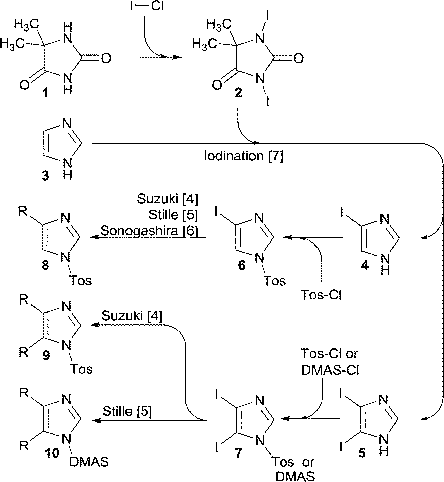 | ||
| Scheme 1 Iodination of 1H-imidazole 3 using 1,3-diiodo-5,5-dimethyl-imidazolidine-2,4-dione 2 as the iodination reagent to selectively obtain 4 or 5. Subsequently an auxiliary group (Tos or DMAS) is introduced to provide the corresponding key intermediates 6 or 7. The title compound, iodination agent 2, was produced by treating 5,5-dimethyl-imidazolidine-2,4-dione 1 with I–Cl as described in this article. | ||
For further progress of this project (Scheme 1), we needed multi-100 gram supplies of the iodoimidazoles 4 and 5, which called for a DIH supply in a timely and economical fashion.
Thus, we decided to develop a synthesis for this purpose, and to exploit flow reactor technology, such technology has been demonstrated as an efficient and versatile tool for both academic research as well as industrial applications.8,9
In our group, we have previously designed, crafted, and developed a versatile multi-jet oscillation disk (MJOD) continuous flow reactor platform,10 which we have used earlier for both classical and metal-catalysed synthetic reactions,10 organo-catalyzed epoxidation of alkenes,11 a multi-step telescoped process allowing preparation of kg day−1 quantities of phenylboronic acids at cryogenic conditions,12 and transition metal-catalysed continuous flow olefin metathesis.13 We presumed that the title compound 2 could, in a straightforward manner, be prepared using the readily available and cheap 5,5-dimethyl-imidazolidine-2,4-dione 1 as a substrate and iodine monochloride (I–Cl) as the iodinating reagent and ultimately implement this as a flow mode synthesis.
Results and discussion
Explorative investigations
A literature search related to the outlined reaction, 1 + ICl → 2, revealed only a few previous reports.14,15 We commenced testing of the process disclosed by Bertorello and coworkers14 (Scheme 2). Carbon tetrachloride was described as the reaction medium for this process, but since CCl4 is reported as a potent hepatotoxin,16 we replaced CCl4 with dichloromethane as the reaction medium. The process appeared to proceed as described, inter alia, and the process should cease by precipitation of the target molecule 2 as a yellowish solid. Unfortunately, in the place of the claimed product 1,3-diiodo-5,5-dimethyl-imidazolidine-2,4-dione 2, we isolated only a product that was proven to be iodoform 11 (Scheme 2). This result called for a re-development. Our introductory screening was based on a 5 mmol (0.65 g) scale of substrate 1, where we screened some bases (NaOH, KOH, and K2CO3) and solvents that included dichloromethane, N,N-dimethylformamide, and ethyl acetate. Furthermore, an iodination mixture composed of I–Cl in ethyl acetate was added dropwise to a cold (0 °C) solution of 5,5-dimethyl-imidazolidine-2,4-dione 1 in aqueous K2CO3. The product 1,3-diiodo-5,5-dimethyl-imidazolidine-2,4-dione 2 was precipitated/crystallized during the course of the reaction and isolated from the post-reaction mixture as a dark reddish solid by means of simple filtration.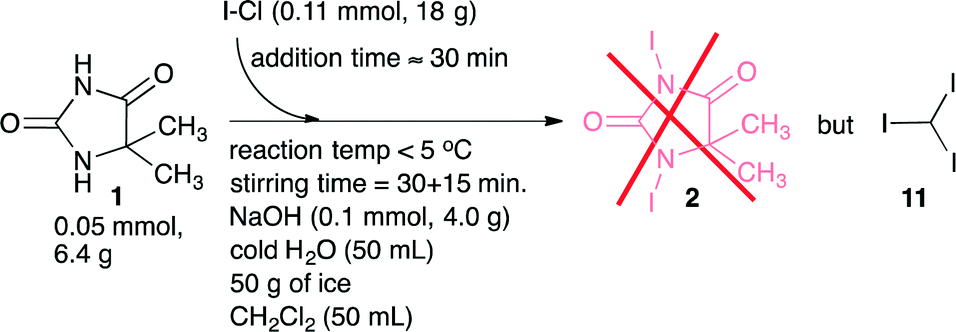 | ||
| Scheme 2 Attempts to prepare 1,3-diiodo-5,5-dimethyl-imidazolidine-2,4-dione 2 according to a literature14 procedure. The procedure provided however iodoform 11 in the place of the expected product 2. | ||
The isolated product was washed with ethyl acetate to remove residual I–Cl, which finally provided a light brown/beige coloured solid. The target product 2 was identified and confirmed by means of ESI-MS, 1H and 13C NMR, FT-IR and TGA (Fig. 6 in the experimental section). The recorded data are disclosed in the experimental section. The full spectra and additional recorded data are disclosed in the ESI.† The conditions of our explorative iodinating process are summarized in Scheme 3.
 | ||
| Scheme 3 Explorative batch scale (5 mmol substrate 1) synthesis of 1,3-diiodo-5,5-dimethyl-imidazolidine-2,4-dione 2. | ||
Scale-up and optimization
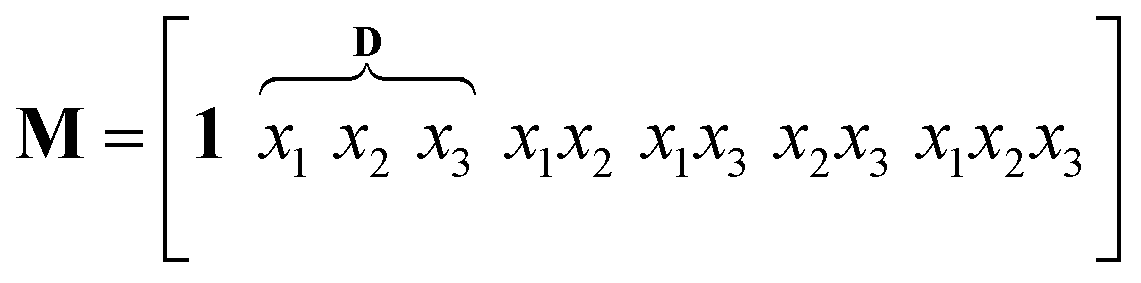
The outlined process, Scheme 3, was then subjected to scale-up and further optimization by means of statistical experimental design17 and multiple linear regression18 using MATLAB19 software. We opted for a ten-fold scale-up, which matched the batch to flow process transfer using our MJOD flow reactor platform.10,20The experimental variables z1, the quantity of the base K2CO3, and z2, the quantity of the iodination reagent I–Cl, were also considered, and z3, the addition time for I–Cl, was explored, and furthermore the total reaction time ttot = z3 + tst, where tst is the stirring time after complete addition of the iodination reagent I–Cl. The tst and all of the other experimental variables were kept at fixed levels for the designed experiments (Table 1). The model matrix M was created according to eqn (1) by means of the design matrix D scaled according to eqn (2), which facilitates the modelling and the subsequent model interpretation.
 | (1) |
 | (2) |
| z k | Experimental variables | Experimental levels | |||
|---|---|---|---|---|---|
| −1 (L) | 0 | +1 (H) | |||
| z 1 | Quantity of K2CO3 | 140 | 150 | 160 | (mmol) |
| 19.35 | 20.73 | 22.11 | (g) | ||
| z 2 | Quantity of I–Cl | 100 | 110 | 120 | (mmol) |
| 16.24 | 17.86 | 19.48 | (g) | ||
| z 3 | Addition time | 60 | 90 | 120 | (min) |
| #a | Experimental variablesb,c | Responsesd | |||
|---|---|---|---|---|---|
| z 1 | z 2 | z 3 | iy (g) | y (%) | |
| a The table is given in standard order. First, experiments #1, 8, and 9 were performed in order to assess whether the experimental levels were appropriately selected, and they showed a variation of 7% points. Then, the other experiments were conducted in random order. b Procedure: potassium carbonate (140, 150, 160 mmol) was placed in a glass cylinder reactor (D = 7.5 cm) and dissolved in cold water (100 mL). 5,5-Dimethyl-imidazolidine-2,4-dione 1 (50 mmol, 6.4 g) was then added and cooled at <10 °C on an ice bath. To this mixture, a solution of ICl (100, 110 or 120 mmol) in ethyl acetate (100 mL) was added dropwise during a period of 60 min under vigorous stirring using a magnetic stirrer bar (L = 35 mm). After the completion of addition, the reaction mixture was stirred continuously for another 50 min. Then the precipitated product was filtered off, washed with a mixture of water and thiosulfate and dried under vacuum, and then finally dried for 10 h at room temperature. The experiment was performed in the dark. c Type of experimental design: 2k + 3, k = 3. d Responses and explanations. iy: weight of isolated product (isolated yield). Theoretical yield is 18.9 g. y = yield% of target product 2. e Mean: 57.9 with standard deviation Std = 1.83. | |||||
| 1 | 19.35 | 16.24 | 60 | 11.88 | 62.5 |
| 2 | 21.11 | 16.24 | 60 | 7.83 | 41.2 |
| 3 | 19.35 | 19.48 | 60 | 9.86 | 51.9 |
| 4 | 21.11 | 19.48 | 60 | 7.97 | 42.0 |
| 5 | 19.35 | 16.24 | 120 | 3.96 | 20.9 |
| 6 | 21.11 | 16.24 | 120 | 3.22 | 16.9 |
| 7 | 19.35 | 19.48 | 120 | 7.32 | 38.5 |
| 8 | 21.11 | 19.48 | 120 | 10.54 | 55.5 |
| 9e | 20.73 | 17.86 | 90 | 10.61 | 55.9 |
| 10e | 20.73 | 17.86 | 90 | 11.07 | 58.3 |
| 11e | 20.73 | 17.86 | 90 | 11.31 | 59.5 |
Modelling and iso-contour projection for the batch process
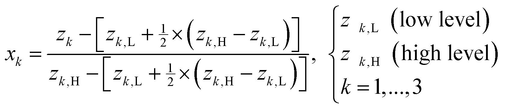
Multiple linear regression (MLR)18 expressed by eqn (3) was used to estimate the numerical values of the regression coefficients that are graphically presented in the stem plot of Fig. 1(b). The adjacent cumulative normal probability (CND)21 plot of Fig. 1(a) reveals β2, β3, and β23 to be the only significant coefficients. The final empirical model including numerical values for the coefficients is given in eqn (4):| y = Mb ⇒ b = (MTM)−1MTy | (3) |
| y = f(x2,x3) = 45.737 + 6.795x2 − 8.233x3 + 8.263x2x3R2 = 0.566, RAdj2 = 0.379, RMSEP = 9.735, RSD = 10.763 | (4) |
 | ||
| Fig. 1 (a) The cumulative normal probability (CND) plot suggests that the regression coefficients β2, β3, and β23 are significant. (b) Regression coefficient spectrum. Product statistics for the full model are: R2 = 0.744, RAdj2 = 0.146, RMSEP = 7.475, and RSD = 8.264. | ||
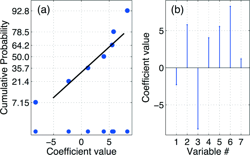
The achieved model, eqn (4), was then used to produce an iso-contour projection of the response surface that was proven to be a saddle-shaped response surface (Fig. 2(a)). By means of this iso-contour projection map, the conditions for an optimization experiment were designated. A yield of 62% of target product 2 was predicted, as shown by the bullet point on the iso-contour projection under the conditions: x1 = −1 (quantity of K2CO3 = 19.35 g/140 mmol), x2 = −1 (quantity of I–Cl = 17.86 g/110 mmol), and x3 = −2 (addition time (taddition) for I–Cl = 30 min).
 | ||
| Fig. 2 (a) Iso-contour projection of the response surface describing the influence of the experimental variables (x2 and x3) on the outcome (the yield) of the iodination batch process leading to 1,3-diiodo-5,5-dimethyl-imidazolidine-2,4-dione 2. The inner square shows the experimental domain of variables x2 and x3. The bullet point shown at x1 = −1 (quantity of K2CO3 = 19.35 g/140 mmol), x2 = 0 (quantity of I–Cl = 17.86 g/110 mmol), and x3 = −2 (addition time (taddition) for I–Cl = 30 min), using a substrate quantity of 6.41 g (50 mmol) and a two-phase liquid system composed of water (100 mL) and ethyl acetate (100 mL), predicts a yield of 62%. (b) Results of monitoring the progress of the batch mode process after complete addition of the iodinating reagent I–Cl. | ||
The choice of these reaction conditions was made on the basis of the iodination reaction stoichiometry, 2 ICl + 1 → 2, concomitant with minimized levels of the other inputs to simplify the work-up and reduce the amount of side streams, which also will contribute to a cost-effective process.
Unfortunately, the model prediction failed outside the investigated domain, as the model prediction ymodel = 62% while the optimizing experiment delivered yobtained = 55%, which however is within the estimated root-mean-square of error prediction. Thus, taking into account also the finding regarding the tst, the final batch optimized procedure was conducted using the predicted values as selected from the iso-contour map of Fig. 2(a), but using a stirring time (tst) that corresponded to only the half of the stirring time used throughout the statistical experimental design.
The effect of the stirring time tst
Using the model prediction of Fig. 2(a), a series of additional experiments was performed in order to evaluate the influence of the stirring time variable,22 that was selected in the range tst ∈ [0 300]. The achieved outcomes of these experiments are displayed as a line graph in Fig. 2(b), from which it is evident that a stirring time of tst ≈ 30 min is optimal for the batch iodination process.The effect of reduced residence time, namely by using tst ≈ 30 min, was highly beneficial for the iodination process, as these alterations provided an increased yield of >10% point to approach a yield of >67%. All details regarding the ultimate optimized batch procedure are provided in the experimental section.
Transfer of the optimized batch process to a flow process
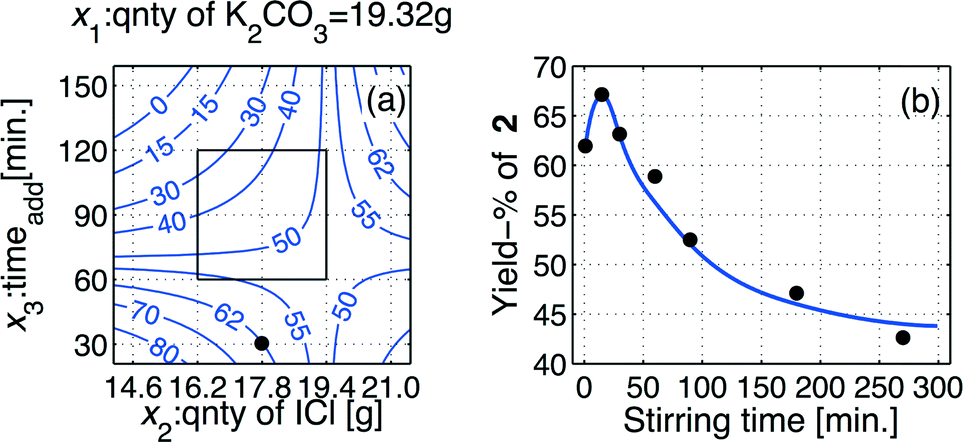
With a reasonably good iodination batch process in hand, we could focus our effort toward the implementation of the process on our proprietary multi-jet oscillating disk (MJOD) flow reactor platform. Previously, we have described in detail the design and how the MJOD flow reactor operates.10 The outline of the current flow iodination process is shown in the process flow diagram of Fig. 3, where (a) shows the outline for the continuous flow reactor part, and (b) displays a semi-continuous product isolation step based on vacuum filtration. | ||
| Fig. 3 Continuous flow process: (a) continuous synthesis of the target molecule 1,3-diiodo-5,5-dimethyl-imidazolidine-2,4-dione 2 in an adapted multi-jet oscillation disk flow reactor rig, and (b) semi-continuous work-up based on vacuum filtration using a glass sintered disk in Büchner-type filter funnel. | ||
Our past experiences regarding batch process transfer to the MJOD reactor platform have revealed that a substantially shorter reactor residence time is usually required. In fact, an appropriate MJOD flow reactor residence time has frequently been shown to be up to only a tenth, or even less, compared to the residence time of the corresponding batch protocol.23 This dramatic effect on the reaction rate is ascribed to the large contact area and very good mixing obtained inside the MJOD reactor. At the outset of the flow process implementation, a series of experiments was conducted by means of the MJOD rig in order to explore the influence of the residence time. The results are graphically displayed in the stem plot of Fig. 4, which suggests a residence time in the range t ≈ 6–9 min. We decided to utilize t = 9 min.
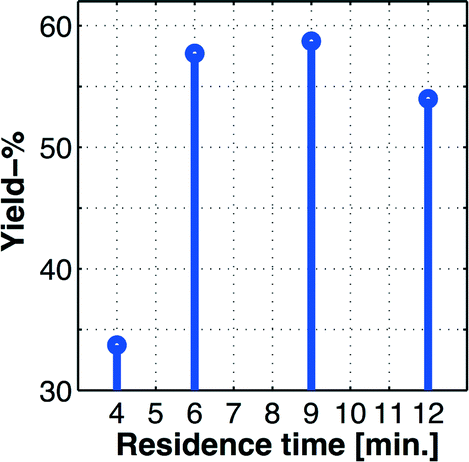 | ||
| Fig. 4 Stem plot showing the % yield based on the isolated product (experimentally measured values shown by bullets (•)) as a function of the residence time in the MJOD continuous flow reactor. The experiments suggest a residence time in the top range of t ≈ 6–9 min. | ||
Introductory continuous flow experiments were performed with the MJOD flow reactor platform including various work-up methods.
During the introductory screening (Table 2), we encountered apparently a major problem; we were not able to isolate target molecule 2 from the quenched post-reaction mixture. Thus, in the place of quenching the reaction mixture, we tried to isolate the product directly by filtration (Büchner filter funnel furnished with coarse pored filter paper), implemented as indicated in (b) of the process flow scheme of Fig. 3. The Büchner filter funnel was positioned at the MJOD flow reactor output line. Although the paper filtration experiment afforded a poor yield only (≈15%), the isolated product was of high purity. This spurred us to further investigate this new strategy using semi-continuous work-up/isolation by filtration in combination with the continuous flow reactor. In succeeding trials, we introduced a Büchner filter funnel equipped with a glass sinter disk (D = 55 mm, Pyrex porosity grade 3) in the place of the paper filter funnel, an amendment that represented a breakthrough for the product isolation and thus the overall process. By means of this technique we were able to collect the major part of the synthesized compound. Reaction details with adjacent results of the exploratory experiments are reported in Table 2.
| # | Experimental variablesa | Responsesb | |||||||
|---|---|---|---|---|---|---|---|---|---|
| m 1 | B | W | I–Cl | S | t | m 2 | y% | WUM | |
| a m 1 = quantity of the substrate 1 (mmol), B = base K2CO3 (mmol), W = H2O (mL), I–Cl = quantity of I–Cl (mmol), S = solvent (ethyl acetate) (mL), m2 = mass (g) of isolated product 2. b y% = yield % of target product 2, WUM = work-up method, where QW = quenched with cold water, PF = filtration using filter paper, and GF = filtration on Büchner funnel furnished with a glass sinter disk (D = 55 mm, porosity grade 3). | |||||||||
| 1 | 150 | 420 | 300 | 330 | 300 | 10 | 1.099 | 1.93 | QW |
| 2 | 100 | 280 | 400 | 220 | 200 | 20 | — | — | QW |
| 3 | 100 | 280 | 200 | 220 | 100 | 20 | 0.304 | 0.80 | QW |
| 4 | 50 | 140 | 100 | 110 | 50 | 4 | 2.869 | 15.10 | PF |
| 5 | 50 | 140 | 100 | 110 | 50 | 4 | 6.407 | 33.72 | GF |
Further development of the MJOD flow process
During the initial discovery of the batch procedure, we observed a substantial degradation/loss of target product 2 at a prolonged residence time (Fig. 2(b)). This was a strong suggestion that our target molecule 2 had to be taken quickly out of solution to avoid product losses. The process flow diagram of Fig. 3(b) shows how the semi-continuous work-up was assembled using two vacuum Büchner filter funnels (F1 and F2) with a glass sinter disk (D = 55 mm, porosity 3) implemented together with a reservoir (R4) that was used to collect the filtrate.The output line from the MJOD flow reactor was directly connected to the current filter unit (F1 or F2) that was utilized until the filter volume was complete. The filter unit F1 was then interchanged with the filter unit F2. By means of this semi-continuous filter unit, the target product 2 (insoluble in the reaction medium) could immediately be taken out from the heterogeneous post-reaction mixture.
Residence time of the flow process
The scaled-up (10×) optimized batch process that afforded a yield of 67% when a total reaction time of 45 min was adapted to the multi-jet oscillating disk (MJOD) flow reactor platform described above. A highly selective and high throughput process (47 g h−1, which corresponds to a reactor residence time of 9 min) was achieved.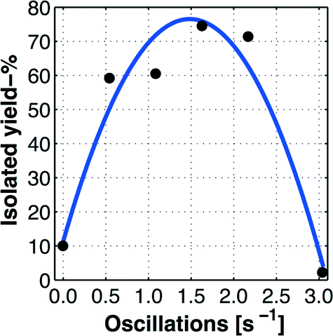 | ||
| Fig. 5 Determination of optimal oscillation number for the MJOD unit assembly of the flow reactor. The graph demonstrates the optimal oscillation number of fopt ≈ 1.6 Hz. The graph line represents the predicted (interpolated) values based on a model obtained from curve fitting using the measured values indicated by the bullets (•). | ||
We interpreted this observation (Fig. 5 and 4) in the following way: target product 2 is formed during a reactor residence time of 9 min, a reaction that demands a certain oscillation rate (mixing rate). The obtained product 2 is not soluble and precipitates/crystalizes and forms solid agglomerates during the course of the process. At low oscillation rates, the mixing is not sufficient and the reaction is incomplete. At higher oscillator rates (i.e. when f > 1.5–1.6 Hz), the agglomerates of the precipitated product are comminuted into smaller particles, which can pass through the pores of the glass sinter disk of the Büchner funnel.
This could of course be compensated by replacing the existing glass sinter disk with a disk of a smaller pore size, however such an alteration will also imply a lower efficiency of the filter unit due to prolonged filtration time.
Long time run experiment
As an ultimate test of the developed continuous flow process, we implement a long time (8 h) test run using the MJOD flow reactor platform. In such an experiment, we expect that the effects of instabilities that may be present in the initial (start-up) and final phase of the flow process will be minimalized or even completely removed and thus provide a measure of the flow process stability. With a residence time of 9 min and a net flow reactor volume Vnet ≈ 80 mL, this corresponds to a total flow volume of >50 × Vnet (5000 mL). The 8 h run experiment required a total of 14 filter funnels where 25–27 g of target molecule 2 was isolated within a run time of ≈35 min each. The two filter funnels F1 and F2 were used alternately. When one was used for product isolation, the other one was subjected to manual work in order to collect the formed target product and was prepared for the next filtration sequence. In total, the 8 h run experiment affords 375 g of the pure title compound 2, which corresponds to an isolated yield of ≈90%.Di-iodination of imidazole 3 using DIH
Target product 2, which was isolated after a long time (8 h) run experiment (see the section above), was air dried in a dark environment, pooled, homogenized, and stored in the dark under argon in a fridge for a period of 12 months. During this period, a series of experiments for the production of 4,5-diiodoimidazole 5 (Scheme 4) was performed using our previously disclosed iodination process,7 where a recent series of five experiments afforded the following outcomes y% ∈ [99 99 97 98 97], which gives a mean yield of ȳ% = 98% (Scheme 4).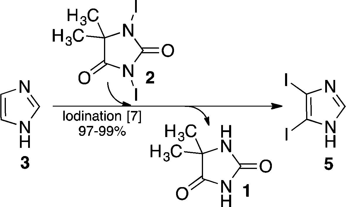 | ||
| Scheme 4 Iodination of the backbone of imidazole 3 using 1,3-diiodo-5,5-dimethyl-imidazolidine-2,4-dione 2 that was produced using our flow process implemented on the MJOD flow reactor platform. | ||
Experimental
General methods
All reagents and solvents were purchased from commercial suppliers (Sigma-Aldrich) and used without further purification.![[thin space (1/6-em)]](https://www.rsc.org/images/entities/char_2009.gif) 000–200 cm−1, Thermo Electron Corporation.
000–200 cm−1, Thermo Electron Corporation.
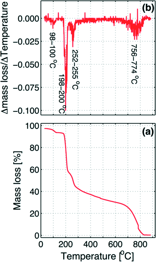 | ||
| Fig. 6 (a) TGA plot: temperature (T) versus mass loss % and (b) graphical presentation of the numerical differentiation (incremental differences) of temperature (T) and mass loss % (mL%) ΔT/ΔmL% which is mapped on the temperature starting from the beginning point (that is, the forward difference). | ||
The graph shows four inflection points, where the first step occurs at 98–100 °C, which corresponds to the loss of residual water left in the sample, evaluated as about 4% of the total mass. At a temperature of 198–200 °C, the decomposition takes places with the loss of one of the two iodine atoms.
The mass decrease in the second step is about 35% of the mass of the dry sample, which is in agreement with the loss of one iodine atom. In the third step at 252–255 °C, when the first iodine is practically completely removed, the second iodine begins to be slowly released until about 756 °C where the remaining molecule skeleton decomposes (fourth step above 756–774 °C). As in the second step, also the mass decreases in the third step, due to the exit of the second iodine atom, corresponding to about 35% of the initial dry sample mass.
The flow reactor
We have previously disclosed10 a detailed account related to the construction and how the MJOD flow reactor platform operates, but a short description is given as follows:Fig. 7 shows a flow chart with specification of the MJOD flow reactor utilized for the development and investigations described herein.
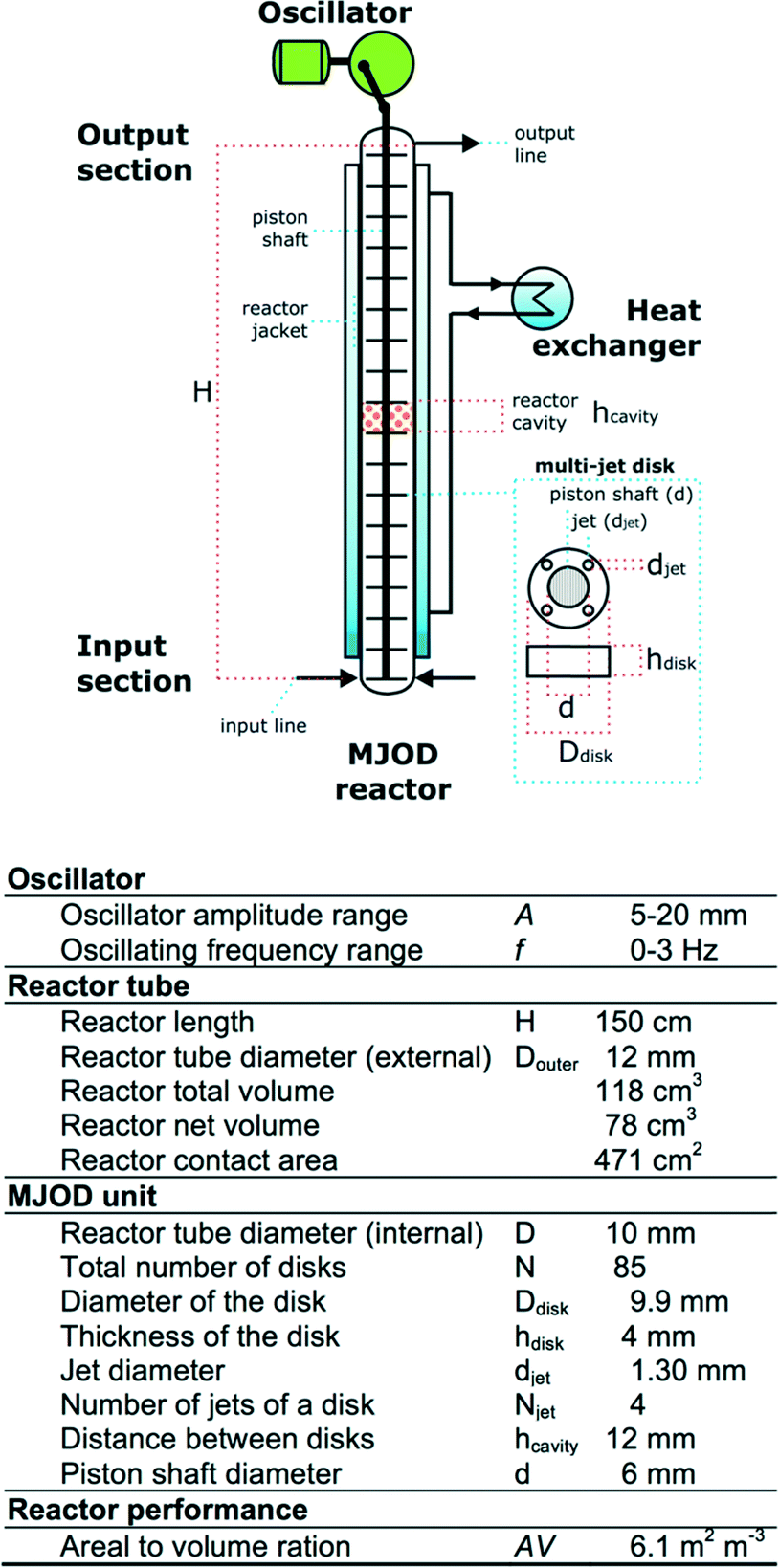 | ||
| Fig. 7 Outline of the MJOD flow reactor with specifications. | ||
The MJOD flow reactor is composed of a relatively short length (height, H) tubular reactor placed in vertical direction with a multi-jet unit that is placed in the centre of the reactor tube. The MJOD unit is composed of a certain number N of multi-jet disks and disk spacers (N − 1). The MJOD assembly is affected by a force from a cam wheel connected to a DC motor that delivers an up and down motion of the entire MJOD unit. This MJOD unit can be compared to a piston in an engine, albeit a piston with many piston heads (disks) (Fig. 7). The reactants are pumped24 at a pre-programmed rate from adjacent resource reservoirs (Fig. 3) to achieve a desired ratio of the reactants when they encounter in the input section of the reactor and to obtain desired reactor residence time. To prevent kick-back to the feeding pumps that can be caused by pressure delivered from the oscillating MJOD unit, each input line (the tube connection between the pump and the reactor input section) was furnished with one-way valves.25 The post-reaction mixture is collected at the output section of the reactor. The oscillator can be pre-set to provide amplitude A and an oscillator frequency f.
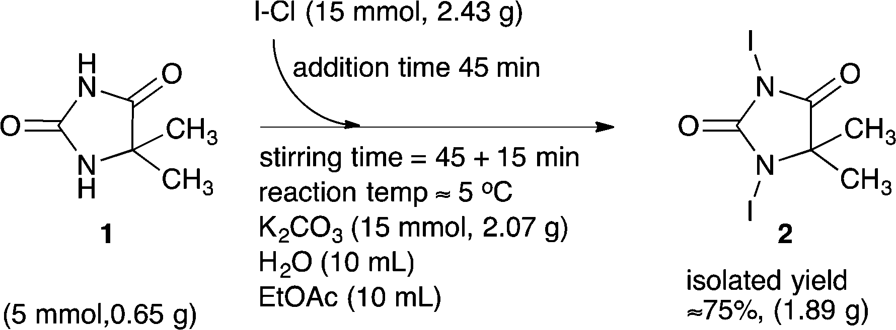
Optimized batch synthesis of DIH
An aqueous solution (100 mL) of K2CO3 (19.32 g, 140 mmol) was placed in a glass reactor (cylinder form, i.d. 7.5 cm, h 10 cm).5,5-Dimethyl-imidazolidine-2,4-dione 2 (6.4 g, 50 mmol) was then added to the basic solution and dissolved by means of a magnetic stirrer bar. The resulting reaction mixture was cooled at T < 5° C using an ice bath. Under vigorous stirring, a solution of iodine monochloride (17.8 g, 110 mmol) in ethyl acetate (100 mL) was added by means of a piston pump over a period of tadd ≈ 30 min. The reaction temperature was controlled at T < 10 °C. After complete addition of the I–Cl solution, the reaction mixture was continuously stirred for another 15 min. Thereafter, the reddish coloured solid product was filtered, washed with cold water and then dried to obtain a slightly brown powder. All the operations were performed in the dark.
ESI-MS found m/z 380.8595. 1H NMR (400 MHz equipped with a 5 mm multinuclear probe with reverse detection was used to record the spectra. 32 scans were used to acquire with an acquiring time of 5 seconds). Solvent DMSO-d6, δ = 0.99 ppm, acetone-d6, δ = 1.06 (s) ppm. 13C NMR (100 MHz equipped with a 5 mm multinuclear probe with reverse detection was used to record 256 scans, which were used to acquire with an acquiring time of 5 seconds). DMSO-d6, δ = 183.8, 162.6, 65.2, 26.0 ppm. FT-IR 1706.9, 1689.7, 1577.6, 1519.0, 1380.6, 1340.5, 1294.4, 1221.1, 1161.0, 1112.9, 828.8, 769.7, 629.1 cm−1.
Optimized continuous flow synthesis of DIH
The continuous flow reactor platform based on the MJOD reactor was assembled as outlined in Fig. 3 and 7. Iodination reagent (I–Cl) and substrate 2 solutions were prepared and placed in their own reservoir, labelled as R1 and R2 & R3 respectively (process flow diagram provided in Fig. 3). The temperature of the reactor heating/cooling loop that includes the heat exchanger and the tubular reactor jacket was controlled at T ≤ 10 °C.The reservoir R1 was charged with a solution of 5,5-dimethyl-imidazolidine-2,4-dione 1 (1.1 mol, 140 g) dissolved in 2.2 L of aqueous potassium carbonate (425 g, 3.1 mol).
Reservoir R2 & R3 was alternately filled with small portions (V ≈ 110 mL) of I–Cl solution. Only small volume portions of I–Cl were prepared during the long production test run (time = 8 h) in order to avoid decomposition of I–Cl, and several small portions of the iodination solution were prepared by dissolving I–Cl (39.2 g, 0.24 mol, 95% assay) in ethyl acetate (V ≈ 110 mL).
The substrate solution was pumped (P1) into the MJOD flow reactor at a rate of 4.69 mL min−1, and the iodination reagent (I–Cl) was pumped (P2) at a rate of 2.35 mL min−1.
Protected from daylight, the target product from the MJOD reactor output line was semi-continuously isolated by means of a Büchner filter funnel equipped with a glass sinter disk of diameter D = 55 mm with Pyrex porosity grade 3.
Di-iodination of imidazole (3)4
Imidazole (0.080 g, 1.18 mmol) and 1,3-diiodo-5,5-dimethyl-imidazolidine-2,4-dione 2 (0.446 g, 1.40 mmol) was added to a round-bottom flask (10 mL) and cooled on an ice bath. Water (2 mL) was then added and the mixture was stirred vigorously whereupon sulfuric acid (1 mL) was added dropwise. The reaction mixture was then quenched by adding the reaction mixture to a flask (50 mL) containing NaOH solution (3.9 M, 15 mL). The quenched reaction mixture was then neutralized with acetic acid to pH 6–7 whereupon the di-iodinated imidazole 5 precipitated. The precipitated product 5 was filtered off on a Büchner funnel with filter paper under reduced pressure, washed with ice water (10 mL), air dried, and finally collected to give 4,5-diiodoimidazole in a typical isolated yield of 98% (1.16 mmol). The identification of the isolated product was performed by comparison with an authentic sample. 1H NMR (400 MHz, DMSO-d6), δ = 12.9 (1H, br, s), 7.7 (1H, s) ppm.Conclusions
We have developed and optimized a multi-gram batch process and a multi-100 g scale continuous flow process for the preparation of 1,3-diiodo-5,5-dimethyl-imidazolidine-2,4-dione 2. The batch process produces the title compound 2 in a good yield (67%) with a short reactor residence time (t = 15 min). The flow process was developed and implemented on the multi-jet oscillating disk (MJOD) flow reactor platform with a working volume of ≈80 mL. The optimized process provided target molecule 2 at a high selectivity and throughput (47 g h−1 at a reactor residence time of 9 min). A test run using the optimized conditions for a 8 h run produced 375 g of pure target product 2 that was isolated by means of a telescoped semi-continuous filtration step, collected from in total 14 filter Nutches in an isolated yield of ≈90%.Furthermore, this study has demonstrated that our MJOD continuous flow reactor platform can exploit product precipitation/crystallization that occurs during the course of the reaction. Product precipitation in most of the flow micro-reactor platforms will result in clogging of the tiny channels and thus cause breakdown for the reactor.
Acknowledgements
M. F. thanks Politecnico di Milano for travel grants. A. D. gratefully acknowledges Department of Chemistry at the University of Bergen for his research fellowship. H. R. B. acknowledges the Faculty of Mathematics and Natural Sciences at University of Bergen for funding a sabbatical leave to Politecnico di Milano in 2013.Notes and references
- K. L. Seley, S. Salim, L. Zhang and P. I. O. Daniel, J. Org. Chem., 2005, 70, 1612–1619 CrossRef CAS.
- F. B. Panosyan and W. J. Still, Can. J. Chem., 2001, 79, 1110–1114 CrossRef CAS.
- N-Heterocyclic Carbenes in Synthesis, ed. S. P. Nolan, Wiley, New York, 2006, pp. 1–319 Search PubMed; O. Kuhl, Functionalised N-Heterocyclic Carbene Complexes, Wiley, New York, 2010, pp. 1–364 Search PubMed; N-Heterocyclic Carbenes in Transition Metal Catalysis and Organocatalysis, ed. C. S. J. Cazin, Springer, Dordrecht, 2011 Search PubMed.
- A. H. Sandtorv and H.-R. Bjørsvik, Adv. Synth. Catal., 2013, 355, 3231–3243 CrossRef CAS.
- A. H. Sandtorv, K. W. Törnroos and H.-R. Bjørsvik, Eur. J. Org. Chem., 2015, 3506–3512 CrossRef CAS.
- A. H. Sandtorv and H.-R. Bjørsvik, Eur. J. Org. Chem., 2015, 4658–4666 CrossRef CAS.
- A. H. Sandtorv and H.-R. Bjørsvik, Adv. Synth. Catal., 2013, 355, 499–507 CrossRef CAS.
- (a) Microreactors in Organic synthesis and catalysis, ed. T. Wirth, Wiley-VCH, New York, Weinheim, 2009 Search PubMed; (b) C. Wiles and P. Watts, Micro Reaction Technology in Organic Synthesis, CRC-Press, Boca Raton, 2011 Search PubMed; (c) Continuous Flow Technology in Industry, Proceedings from the Royal Society of Chemistry's Special Chemicals Sector Symposium, York, England, 2012 Search PubMed; (d) Chemical Reactions and Processes under Flow Conditions, ed. S. V. Luis and E. Garcia-Verdugo, Royal Society of Chemistry, Cambridge, 1st edn, 2010 Search PubMed.
- (a) Microreactors in Organic synthesis and catalysis, ed. T. Wirth, Wiley-VCH, New York, Weinheim, 1st edn, 2009 Search PubMed; (b) S. V. Ley, D. E. Fitzpatrick, R. J. Ingham and R. M. Myers, Angew. Chem., Int. Ed., 2015, 54, 3449 CrossRef CAS PubMed; (c) S. V. Ley, D. E. Fitzpatrick, R. M. Myers, C. Battilocchio and R. J. Ingham, Angew. Chem., Int. Ed., 2015, 54, 10122–10136 CrossRef CAS PubMed.
- L. Liguori and H.-R. Bjørsvik, Org. Process Res. Dev., 2011, 15, 997–1009 CrossRef CAS.
- R. Spaccini, L. Liguori, C. Punta and H.-R. Bjørsvik, ChemSusChem, 2012, 5, 261–265 CrossRef CAS.
- (a) D. Sleveland and H.-R. Bjørsvik, Org. Process Res. Dev., 2012, 16, 1121–1130 CrossRef CAS; (b) A. Desai, Angew. Chem., Int. Ed., 2012, 51, 9223–9225 CrossRef CAS PubMed.
- L. Liguori and H.-R. Bjørsvik, Org. Process Res. Dev., 2014, 18, 1509–1515 CrossRef.
- O. O. Orazi, A. Corral and H. E. Bertorello, J. Org. Chem., 1965, 30, 1101–1104 CrossRef CAS PubMed.
- H. Kodama, T. Katsuhira, T. Hino, K. Takagi and A. Seo, Nihon Nohyaku Co., Ltd., JP 2002030072, 2002, Chem. Abst., 2002, 136:102383, Accession number CApluss 2002: 77467.
- (a) R. O. Recknagel, Pharmacol. Rev., 1967, 19, 145–208 CAS; (b) L. W. Weber, M. Boll and A. Stampfl, Crit. Rev. Toxicol., 2003, 33, 105–136 CrossRef CAS PubMed.
- (a) G. E. P. Box, W. G. Hunter and J. S. Hunter, Statistics for experimenters. Design, Innovation, and Discovery, 2nd edn, Wiley, New York, 2005 Search PubMed; (b) G. E. P. Box and N. R. Draper, Empirical model-building and response surfaces, Wiley, New York, 1987 Search PubMed; (c) G. E. P. Box, Improving almost anything, Ideas and essays, rev. edn, Wiley, New York, 2006 Search PubMed.
- N. R. Draper and H. Smith, Applied Regression Analysis, 3rd edn, Wiley, New York, 1998 Search PubMed; D. C. Montgomery and E. A. Peck, Introduction to linear regression analysis, Wiley, New York, 1982 Search PubMed.
- (a) The MATLAB program was utilized for the graphical representation of the results and models, see Using MATLAB Version 6 (Nov. 2000), The MathWorks, Inc., Natick, MA, USA Search PubMed; (b) Using MATLAB Graphics Version 6 (Nov. 2000), The MathWorks, Inc., Natick, MA, USA Search PubMed.
- In contrast to continuous flow micro-reactors with net reactor volumes in μL scale, the multi-jet oscillating disk (MJOD) continuous flow reactor is constructed to operate at multi mL volumes scale, typically 40–100 mL. The MJOD flow reactor rig utilised in the present work possessed a net tubular volume of ≈80 mL.
- (a) C. Daniel, Technometrics, 1959, 1, 311–341 CrossRef; (b) C. Daniel, Application of Statistics to Industrials Experimentation, Wiley, New York, 1976 Search PubMed; (c) See pages 33–34 and 203–205 of ref. 17a.
- Stirring time correspond to the additional reaction time after complete addition of I–Cl to the reaction mixture. Throughout the experimental design tst = 60 min was used.
- In a previous study we implemented and developed an aerobic oxidation process using our MJOD flow reactor platform. This process was developed from a batch protocol that demanded a reaction time of 2–3 days. Implemented on the MJOD rig, identical transformations were carried through at a residence time of only 1–2 h. For details, see ref. 11.
- Pumps from Fluid Metering, Inc. were used. (1) FMI Q PUMP Drive, MODEL QG20 and Pump head model: Q1CKC, that provides a pump rate in the range 0–6.40mL min−1 and (2) FMI Q PUMP Drive, MODEL QBG (12 VDC / 24 VDC) with pump head model: RHLF that provides a pump rate of 0–6.00 mL min−1.
- Inline cartridge check valves (Upchurch Scientific®) from IDX Health & Science, model CV Inline Cartridge 3 psi were used to ensure the flow to one direction. The inline cartridge was placed between the pump and (close to) the reactor inlet.
Footnote |
| † Electronic supplementary information (ESI) available: Full spectra and other recorded analytical data. See DOI: 10.1039/c6re00051g |
| This journal is © The Royal Society of Chemistry 2016 |