
 Open Access Article
 This Open Access Article is licensed under a
 Creative Commons Attribution 3.0 Unported Licence
Controlled generation and use of CO in flow†‡
Steffen V. F.
Hansen
ab,
Zoe E.
Wilson
a,
Trond
Ulven
*b and
Steven V.
Ley
*a
aDepartment of Chemistry, University of Cambridge Lensfield Road, Cambridge, CB2 1EW, UK. E-mail: svl1000@cam.ac.uk (S.V.L.)
bDepartment of Physics, Chemistry and Pharmacy, University of Southern Denmark, Campusvej 55, 5230 Odense M, Denmark. E-mail: ulven@sdu.dk (T.U.)
First published on 25th February 2016
Abstract
A method for the generation and use of carbon monoxide in flow chemistry has been developed. By using a tube-in-tube reactor, oxalyl chloride can be conveniently and safely hydrolyzed using a NaOH solution to generate CO in the outer stream, which then passes through AF-2400 semi-permeable inner tubing to enrich a reaction stream where it is consumed. The tube-in-tube reactor allows the generation of CO under conditions which would otherwise be incompatible with the reaction conditions. In this way carbonylations can be successfully performed in flow without the use of pressurized gas cylinders. Both alkoxy- and aminocarbonylation was carried out in flow, including a 320 minute continuous run, as proof of concept.
Introduction
Carbon monoxide is widely considered to be the most important C1 building block due to the ever expanding range of catalytic carbonylations possible.1 This valuable gas is used in a range of reactions, such as Heck carbonylations, hydroformylation reactions and in the synthesis of diverse heterocycles.1–4 Despite this, widespread adoption of carbonylation chemistry has been limited by the highly toxic and flammable nature of this colorless, odorless and tasteless gas. Most carbonylation reactions are performed using pressurized CO gas cylinders, which present an additional barrier for adopting this otherwise promising chemistry. Flow chemistry allows for safe handling of reactive, toxic and otherwise dangerous reaction components, and offers additional benefits such as improved mass and heat transfer and facile scale up.5 The use of gaseous reagents, including CO, in flow chemistry is well established6 and gasses are usually introduced as slugs by joining a reaction solvent stream with a gas stream. An alternative approach, developed in our group, is the use of a porous gas-permeable Teflon AF-2400 membrane in a tube-in-tube reactor.7,8 This reactor has been used to great success in CO consuming reactions.9,10 While carbonylations in flow chemistry can be performed safely, it does still typically require the use of pressurized CO canisters. If CO is only required seldomly, this introduces the need to store a partially used canister of CO for a longer period. Strategies which avoid the use of CO cylinders in batch have been developed, for example CO surrogates that release CO in situ, which does away with the need to store CO cylinders.11–13 Although this technique has not been used as widely in flow as in batch carbonylations there are some examples. 2,4,6-Trichlorophenyl formate has been reported as a CO surrogate in the Pd catalyzed synthesis of (hetero)aromatic 2,4,6-trichlorophenol esters,14 and the dehydration of formic acid by concentrated H2SO4 has been employed as an in situ CO source for the Koch–Haaf reaction in a specialist hastelloy microreactor.15 The main limitation of these kinds of surrogates is that the chemistry must be compatible with both the surrogate itself and the conditions needed for CO release. Pd catalyzed carbonylation of aryl halides using 2,4,6-trichlorophenyl formate as CO source leads to the corresponding trichlorophenol esters, requiring an additional step to obtain other derivatives, and dehydration of formic acid with H2SO4 limits the reaction to substrates that are very acid resistant. By segregating the CO releasing and CO consuming reactions, these problems can be circumvented. This has, for example, been demonstrated in batch chemistry using the COware two-chamber kit developed by Skrydstrup et al.16 and Brancour et al. have reported one example where they used a modified tube-in-tube setup in flow with the gas permeable Teflon AF-2400 membrane to separate CO production, by H2SO4 mediated dehydration of formic acid at 80 °C, from the CO consuming aminocarbonylation of 4-iodoanisole.17 The permeability properties of membranes have also been exploited for generation and use of anhydrous CH2N2 in flow.18,19 In the Ulven lab, we have recently demonstrated that basic hydrolysis of oxalyl chloride instantaneously yields high quality carbon monoxide at room temperature, which can be exploited in batch carbonylations by collecting the formed gas in a balloon.20 Herein we report the extension of this convenient and atom efficient CO generating methodology to flow chemistry using tube-in-tube technology.Results and discussion
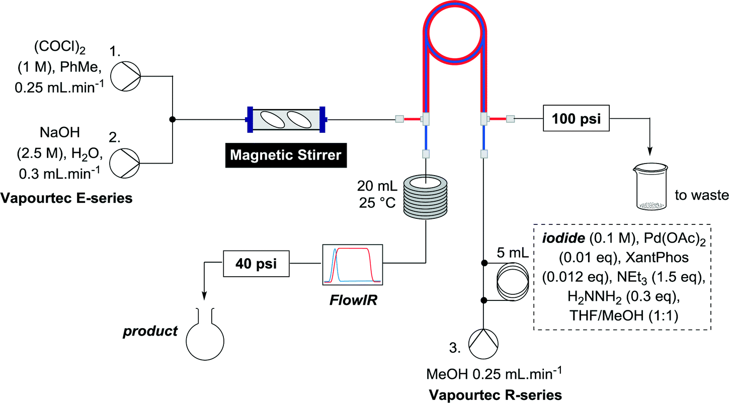
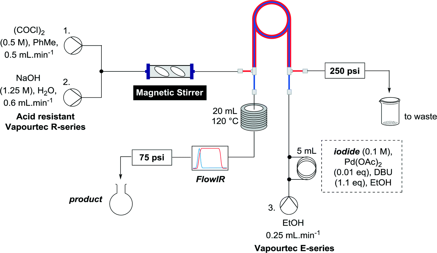
Batch generation of CO was done by slow addition of neat oxalyl chloride to 2 M aqueous NaOH.20 For adaption to flow chemistry careful consideration of chemical compatibility of flow equipment was necessary. For the purposes of flow generation it was considered safer to mix a solution of oxalyl chloride with a solution of NaOH, rather than generating a large excess of CO by using neat oxalyl chloride. Our initial experiments were performed on a Vapourtec E-series system, which employs V-3 peristaltic pumps, the advantages of which we have previously discussed for continuous flow reactions.21 The peristaltic tubing of the pump can be readily switched between two different fluoropolymers of complimentary chemical resistance (colour coded “red” or “blue”) to allow the pumping of a wide variety of chemicals, with the red tubing being resistant to oxalyl chloride at appropriate concentrations for this work. Oxalyl chloride itself is only chemically compatible with hydrocarbons, ethers and chlorinated solvents. On the E-series, ethereal solvents can only be pumped using the blue tubing, which is incompatible with oxalyl chloride, therefore toluene was chosen as the solvent for the oxalyl chloride stream. Mixing a stream of 1 M oxalyl chloride in toluene with a stream of 2.5 M aqueous NaOH, both at 0.25 mL min−1 at a T-piece led to instant gas formation, as determined using a CO monitor (and the visible bubbles), however it was clear that the gas formation was not complete due to the poor miscibility of the two solvent systems. Installation of a mechanical stirrer consisting of an Omnifit column (0.68 mL) with two magnetic stirrer bars after the T-piece alleviated this problem (Scheme 1). While the hydrolysis is exothermic, mixing at this rate did not produce any significant heating, which is one of the inherent benefits of flow chemistry.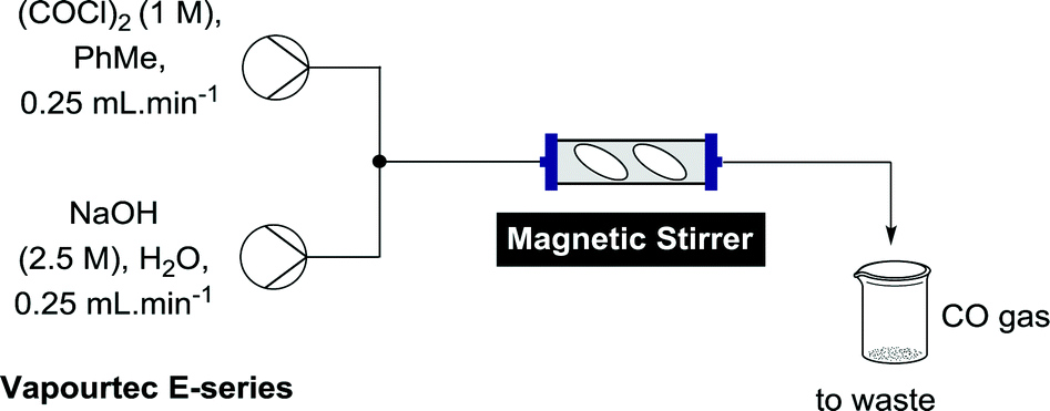 | ||
| Scheme 1 Generation of CO gas in flow. | ||
Methoxycarbonylation of vinyl iodides was chosen as the reaction to evaluate the formation of CO as it has previously been shown to work well using a tube-in-tube flow setup.9
The previous methodology involved the union of a stream of vinyl iodide and NEt3 with another stream containing catalyst, followed by dilution with a solvent stream pre-enriched with CO by passing through a tube-in-tube reactor (Scheme 2).9
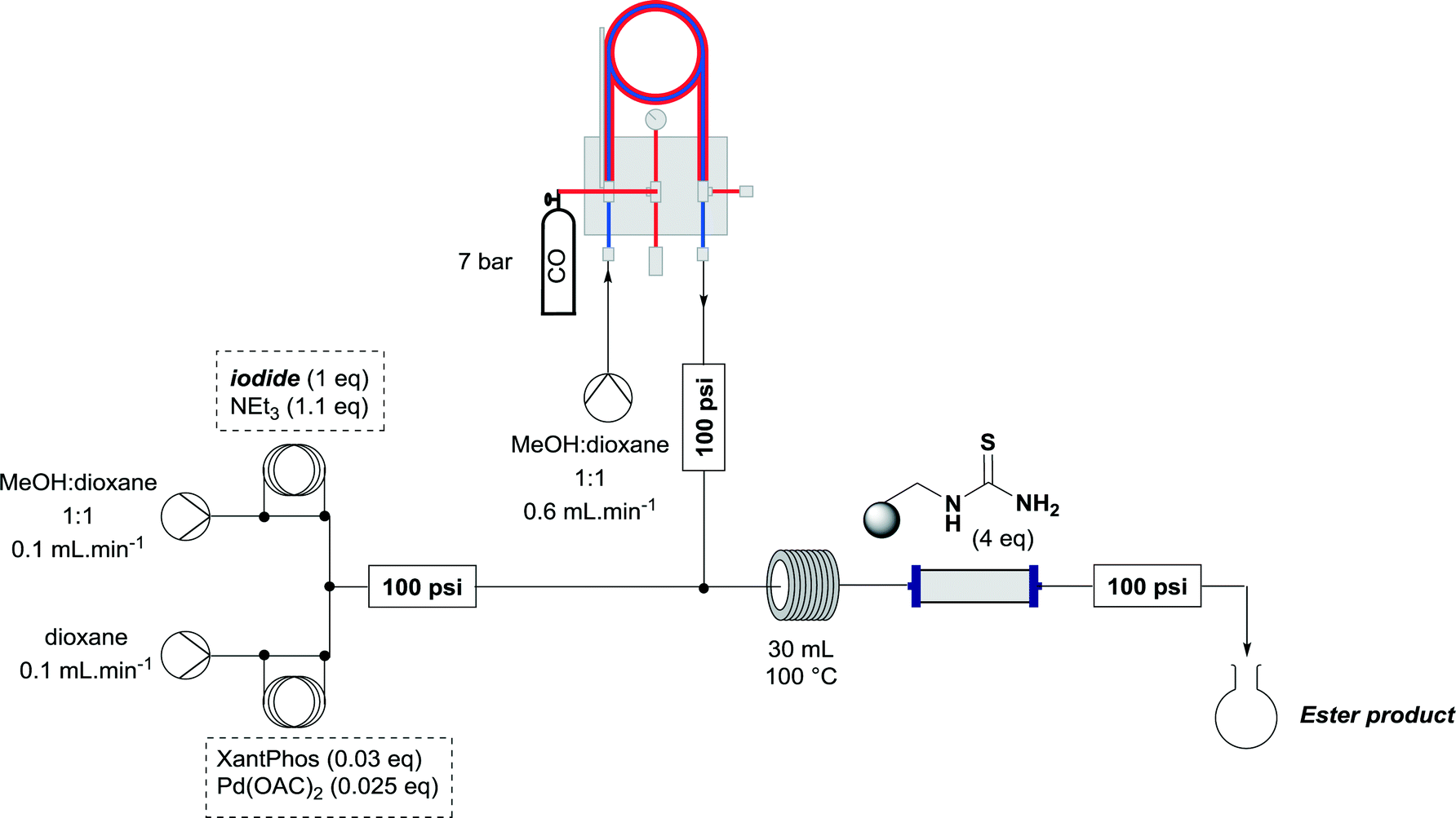 | ||
| Scheme 2 Setup for previous Ley group flow carbonylation using the tube-in-tube reactor.9 | ||
It was considered prudent to determine whether this set up could be simplified, so we opted initially to pre-mix the catalyst, vinyl iodide and base before passing this stream through the tube-in-tube reactor to enrich it with CO, effecting the reaction. The setup was configured such that after mechanical mixing, the CO generating stream was pumped through the outer tube of a tube-in-tube reactor. Plugs of the reaction mixture were injected to a third stream flowing counterflow to the CO generating stream through the inner tube of the tube-in-tube reactor. The reaction mixture initially consisted of vinyl iodide (1) (0.25 mmol), Pd(OAc)2 (0.05 eq.), 4,5-bis(diphenylphosphino)-9,9-dimethylxanthene (XantPhos) (0.06 eq.) and triethylamine (1.5 eq.) in MeOH/dioxane (1![[thin space (1/6-em)]](https://www.rsc.org/images/entities/char_2009.gif) :1) and was pumped at 0.25 mL min−1. After the reaction plug has passed through the tube-in-tube reactor the CO generating reaction is stopped by switching pumps 1 and 2 to toluene and water respectively and the reaction mixture is passed through a 20 mL reaction coil at 25 °C. A FlowIR spectrometer is used in-line to monitor the reaction and guide the collection of reaction plugs. To ensure an appropriate pressure gradient in the tube-in-tube reactor the CO generating stream was fitted with a 100 psi back pressure regulator (BPR), and the reaction stream was fitted with a 40 psi BPR. The reaction plug was purified by concentration then flash chromatography or directly analyzed by crude NMR (Scheme 3).
:1) and was pumped at 0.25 mL min−1. After the reaction plug has passed through the tube-in-tube reactor the CO generating reaction is stopped by switching pumps 1 and 2 to toluene and water respectively and the reaction mixture is passed through a 20 mL reaction coil at 25 °C. A FlowIR spectrometer is used in-line to monitor the reaction and guide the collection of reaction plugs. To ensure an appropriate pressure gradient in the tube-in-tube reactor the CO generating stream was fitted with a 100 psi back pressure regulator (BPR), and the reaction stream was fitted with a 40 psi BPR. The reaction plug was purified by concentration then flash chromatography or directly analyzed by crude NMR (Scheme 3).
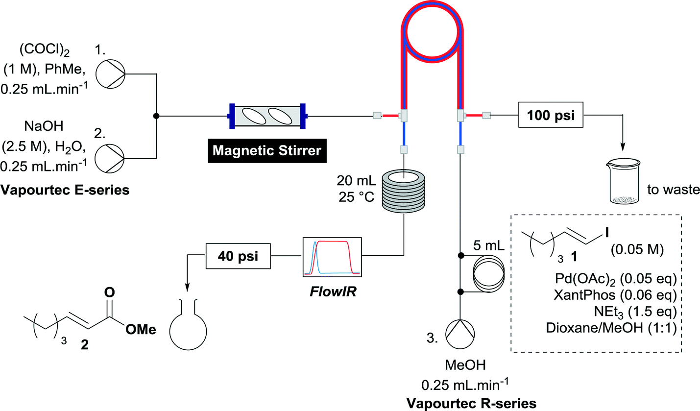 | ||
| Scheme 3 Initial setup for methoxycarbonylation of 1. | ||
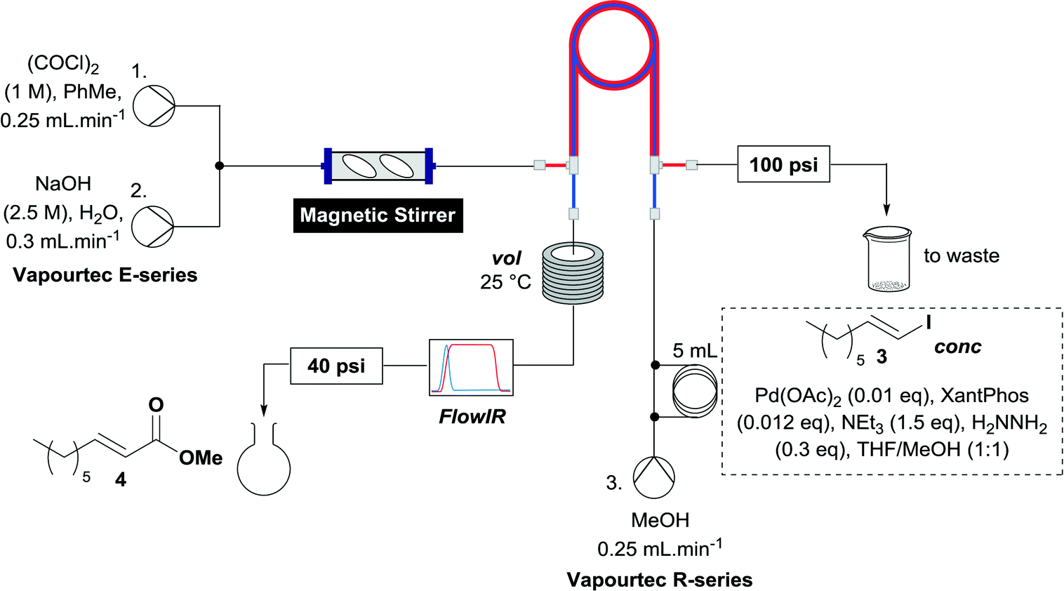
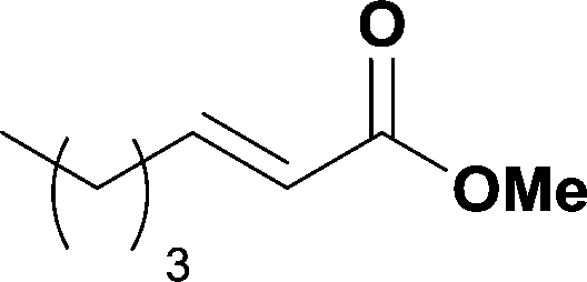
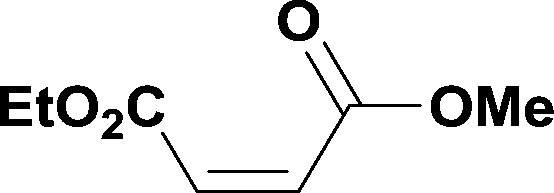
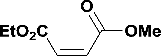
When the first reaction was performed under these conditions it gave full conversion as judged by crude 1H-NMR and TLC, however the reaction produced large amounts of black particles which coated the Teflon AF-2400 tubing. We have previously reported that with similar reaction conditions 4-iodo-1-methyl-1H-pyrazole was methoxycarbonylated in low yields accompanied by rapid Pd0 precipitation, but addition of 30 mol% hydrazine led to an improved yield.9 For this work it was found that addition of 30 mol% of hydrazine (1.0 M in THF), prevented the formation of the black precipitate, however as soon as hydrazine was added a bright yellow compound precipitated. While the heterogeneous mixture could be injected and we observed close to full conversion, the yellow particles blocked the system when they reached the BPR. Reasoning that this precipitate was likely to be a poorly soluble palladium complex, and that if it is not in solution then it is unlikely to be catalytically active we lowered the amount of Pd(OAc)2 and XantPhos to 0.01 eq. and 0.012 eq. respectively. Gratifyingly, this resulted in a homogenous yellow solution and no blockage at the BPR with similar conversion. Due to the volatility of the starting material and product, before isolation of the product was attempted dioxane was replaced with THF and the starting material was changed to the longer homologue 3. We observed an IR band at 2330 cm−1, indicating that some CO2 was crossing into the reaction stream. To neutralize this the ratio of NaOH to oxalyl chloride was increased by raising the flow rate of the NaOH to 0.3 mL min−1. Using these modified conditions we investigated how much CO was crossing the membrane by varying the concentration of the reaction mixture (Table 1, #1–3). The best conversion was obtained when the concentration of iodide 3 was 0.1 M, with conversion dropping considerably when the concentration was increased to 0.2 M. The reaction time was then reduced for the 0.1 M reaction to 40 min (10 mL reaction coil), which resulted in only a slight reduction in conversion, and to ∼1 min (no reaction coil) which resulted in a significant drop in conversion (Table 1, #4 and 5).
|
|
|||||||||
|---|---|---|---|---|---|---|---|---|---|
| Entry | Conc. (M) | Vol. (mL) | Reaction time (min) | Conversion (1H NMR)a | Entry | Conc. (M) | Vol. (mL) | Reaction time (min) | Conversion (1H NMR)a |
| a Conversion was determined by integrating the olefinic protons in the 1H NMR of the reaction mixture. | |||||||||
| 1 | 0.1 | 20 | 80 | >99% | 4 | 0.1 | 10 | 40 | 98% |
| 2 | 0.15 | 20 | 80 | 92% | 5 | 0.1 | 0 | ∼1 | 40% |
| 3 | 0.2 | 20 | 80 | 78% | |||||
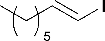
The optimized conditions were then used to synthesize the volatile esters 2, 4 and 6 with complete conversion by crude NMR and acceptable isolated yields (Table 2).
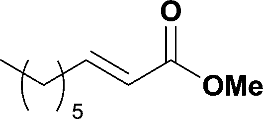
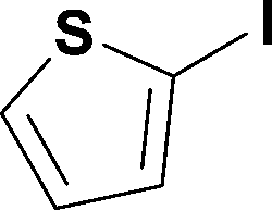
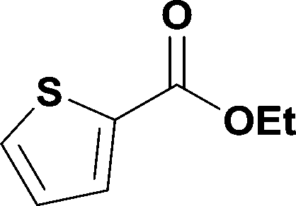
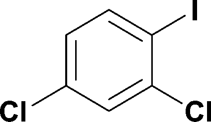
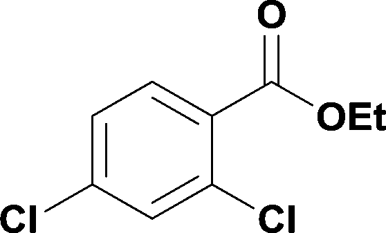
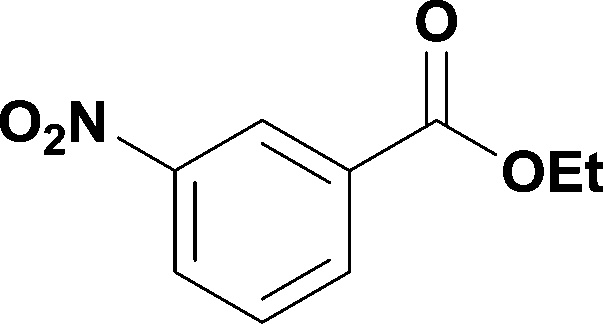
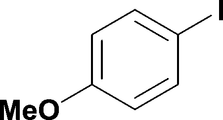
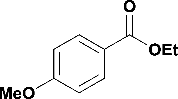
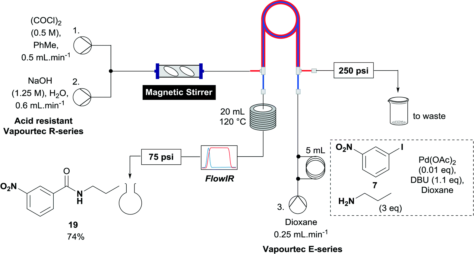
Alkoxycarbonylation of aryl iodides is less facile than of vinyl iodides and requires heating to proceed on a reasonable timescale. To allow heating of the reaction mixture we increased the BPR of the reaction stream to 75 psi. As the E-series system routinely only handles pressure up to ∼145 psi, this limited the size of the BPR which could be used on the CO consuming stream and therefore the pressure gradient across the Teflon AF-2400 membrane. The oxalyl chloride and the NaOH streams were therefore shifted to an acid resistant R-series system (Vapourtec), which can pump up to 600 psi, allowing us to attach a 250 psi BPR to the CO generating stream, with the E series used for the lower pressure reaction stream. At this stage it was decided to halve the concentrations of both the oxalyl chloride and the NaOH streams and double the flow rate for pumps 1 and 2 to afford a more reliable pumping speed. In contrast to the E-series system, the R-series pump is more sensitive to gas bubbles in the solvent stream, and when using this setup we found it essential to flush the pump with dry solvent before use as any residual water led to gas formation in the pump which stopped flow. In order to test this set up the methoxycarbonylation of vinyl iodide 5 was attempted using the chemical reaction conditions employed earlier (Table 3, #1). Pleasingly, methyl ester 6 could be successfully synthesized with full conversion and 71% isolated yield. By applying reaction conditions adapted from a published procedure22 to our setup, using the higher boiling ethanol as solvent, we could then successfully synthesize a range of ethyl benzoates (Table 3, #2–8). With electron deficient iodides 7 and 8 the corresponding ethyl esters 9 and 10 were produced in high yields (96 and 99% respectively) under these conditions, whereas ethoxycarbonylation of electron rich aryl iodides 11–14 did not go to completion, affording esters 15–18 in modest yields (74–79%). To further expand the utility of this methodology, the reaction of iodide 7 was successfully run continuously for 320 minutes to produce 1.47 g (96%) of the ethyl ester.
|
|
|||||||||||
|---|---|---|---|---|---|---|---|---|---|---|---|
| # | Iodidea | Product | Yieldb | # | Iodidea | Product | Yieldb | # | Iodidea | Product | Yieldb |
|
a All reactions were carried out on 0.5 mmol scale apart from #8 which was run continuously on 8 mmol scale (320 minutes).
b Isolated yield.
c Methanol was used as the solvent for pump 3, the reaction coil was heated to 25 °C and sample loop filled with iodide 5 (0.1 M), Pd(OAc)2 (0.01 eq.), XantPhos (0.012 eq.), NEt3 (1.5 eq.), H2NNH2 (0.3 eq.) and THF/MeOH (1:1).
d Continuous flow reaction.
|
|||||||||||
| 1c |
 5
5
|
 6
6
|
71% | 4 |
 11
11
|
 15
15
|
74% | 7 |
 14
14
|
 18
18
|
79% |
| 2 |
 7
7
|
 9
9
|
97% | 5 |
 12
12
|
 16
16
|
8d |
 7
7
|
 9
9
|
96% (1.47 g) | |
| 3 |
 8
8
|
 10
10
|
99% | 6 |
 13
13
|
 17
17
|
78% | ||||
A useful further extension involved the aminocarbonylation of aryl iodides to form amides. Iodide 7 was used to test whether this application was possible using the established reactor system. The reaction solvent was changed to dioxane and 3 equivalents of propylamine was added as the nucleophile, which pleasingly afforded amide 19 in 74% yield (Scheme 4). With the less polar reaction solvent, it was observed that a crystalline precipitate (presumably the salt of the base) precipitated in the heating coils. While a blockage of the system was not observed before the reaction mixture had eluted, this indicates that further optimization of the reaction may be necessary to allow the aminocarbonylation to be run continuously, when the precipitate could accumulate over long periods of time to levels which block the reaction system.
 | ||
| Scheme 4 The aminocarbonylation of aryl iodide 7. | ||
Conclusions
It has been demonstrated that a tube-in-tube reactor allows for the use of oxalyl chloride as a convenient source of CO for flow chemistry reactions, removing the requirement of pressurized gas cylinders. Alkoxycarbonylations of vinyl and aryl iodides were successfully carried out, including a continuous flow example and as further proof of concept the successful aminocarbonylation of an aryl iodide was also accomplished. This work provides an effective alternative method to carry out flow carbonylation chemistry for those in the chemical community who are hesitant to work with CO canisters. Finally, this work provides a good starting point for the generation and use of other toxic and highly reactive gasses in flow in a similar fashion.Experimental section
General comments
Unless stated otherwise, reagents and solvents were obtained from commercial sources and used without purification. Toluene was distilled from calcium hydride, THF distilled from sodium/benzophenone, methanol distilled from Mg, ethanol was used at 99.8% purity, 1,4-dioxane was stored over activated 3 Å sieves, NEt3 was distilled from CaH2 and stored over KOH. No efforts were taken to degas the NaOH or oxalyl chloride solutions before use.Purification by flash chromatography was carried out using silica gel 60 Å (Merck grade 9385) using distilled Et2O, ethyl acetate and petroleum ether (bp 40–60 °C) as eluent system. The removal of solvent under reduced pressure was carried out on a standard rotary evaporator.
1H NMR spectra were recorded on either a 400 MHz DPX-400 Dual Spectrometer or a 600 MHz Avance 600 BBI Spectrometer with the residual solvent peak as the internal reference (CDCl3 = 7.26 ppm). 1H resonances are reported to the nearest 0.01 ppm. 13C-NMR spectra were recorded on the same spectrometer with proton decoupling, with the solvent peak as the internal reference (CDCl3 = 77.16 ppm). All 13C resonances are reported to the nearest 0.1 ppm.
All pressures are given as pressure relative to ambient atmospheric pressure (psig).
Once the reaction mixture has passed through the tube-in-tube the CO generating pumps are switched to solvent (toluene and water respectively) so that the CO generating reaction is only running while needed.
Reactions were followed using Mettler Toledo Flow-IR, monitoring for the products carbonyl stretch (∼1730 cm−1 for esters, ∼1670 cm−1 for amide 19) to allow collection of the reaction plug, from which the solvent was removed in vacuo and the product purified by flash chromatography as indicated.
The tube-in-tube reactor used had an outer tube volume of 1.3 mL and an inner tube volume of 0.3 mL. At the end of each day of use the oxalyl chloride pump was flushed sequentially with THF, water, THF and toluene. If the pump was not properly flushed, residual water could cause gas formation in the pump when oxalyl chloride is next pumped (for the R2+ pump).
CO safety precautions!
General methods
:THF (1:1). The reaction stream passed through the tube-in-tube reactor counter flow to the generation stream, through a 10 mL coil at 25 °C, a Flow-IR and a 40 psi BPR then was collected and purified by flash chromatography.
CO consuming reaction: ethanol was flowed through the inner tube using pump 3 (Vapourtec E series, red peristaltic tubing) at 0.25 mL min−1. Once gas bubbles was observed exiting the tube in tube reactor in the inner stream (typically after running the CO generating for a 10–15 minutes) the reaction mixture was injected as a 5 mL sample loop containing an ethanolic solution of aryl iodide (0.5 mmol), Pd(OAc)2 (1.4 mg, 5 μmol) and DBU (0.1 mL, 0.55 mmol). The reaction stream was passed through the tube-in-tube reactor in the opposite direction to the generation stream, through a 20 mL coil at 120 °C, a Flow-IR and a 75 psi BPR, then collected and purified by flash chromatography.
Representative experimental procedures
:Et2O, 50:1): Rf = 0.30 (pet. ether:Et2O, 20:1): 1H NMR (600 MHz, CDCl3) δ 6.97 (dt, J = 15.6, 7.0 Hz, 1H), 5.81 (dt, J = 15.6, 1.5 Hz, 1H), 3.72 (s, 3H), 2.21–2.17 (m, 2H), 1.47–1.41 (m, 2H), 1.33–1.23 (m, 6H), 0.87 (t, J = 7.0 Hz, 3H); 13C NMR (151 MHz, CDCl3) δ 167.4, 150.1, 120.9, 51.6, 32.4, 31.7, 29.0, 28.1, 22.7, 14.2. The spectral data were in agreement with the literature.23
:Et2O, 8:1): Rf = 0.45 (pet. ether:Et2O, 4:1); mp = 40.1–41.5 °C, lit 36–38 °C; 1H NMR (600 MHz, CDCl3) δ 8.86–8.84 (m, 1H), 8.40 (d, J = 8.2 Hz, 1H), 8.37 (d, J = 7.7 Hz, 1H), 7.65 (t, J = 8.0 Hz, 1H), 4.44 (q, J = 7.1 Hz, 2H), 1.43 (t, J = 7.2 Hz, 3H); 13C NMR (151 MHz, CDCl3) δ 164.6, 148.4, 135.4, 132.4, 129.7, 127.4, 124.7, 62.1, 14.4. The spectral data were in agreement with the literature.24
Acknowledgements
The authors gratefully acknowledge the EPSRC for financial support (grants EP/K009494/1 and EP/K039520/1) and the Danish Council for Strategic Research (grant 11-116196).Notes and references
- A. Brennführer, H. Neumann and M. Beller, Angew. Chem., Int. Ed., 2009, 48, 4114–4133 CrossRef PubMed.
- R. Grigg and S. P. Mutton, Tetrahedron, 2010, 66, 5515–5548 CrossRef CAS.
- X.-F. Wu, H. Neumann and M. Beller, Chem. Rev., 2013, 113, 1–35 CrossRef CAS PubMed.
- M. Beller and X.-F. Wu, Transition Metal Catalyzed Carbonylation Reactions: Carbonylative Activation of C-X Bonds, Springer-Verlag, Berlin Heidelberg, 1st edn, 2013 Search PubMed.
- B. Gutmann, D. Cantillo and C. O. Kappe, Angew. Chem., Int. Ed., 2015, 54, 6688–6728 CrossRef CAS PubMed.
- C. J. Mallia and I. R. Baxendale, Org. Process Res. Dev., 2016, 20, 327–360 CrossRef CAS.
- M. O'Brien, I. R. Baxendale and S. V. Ley, Org. Lett., 2010, 12, 1596–1598 CrossRef PubMed.
- M. Brzozowski, M. O'Brien, S. V. Ley and A. Polyzos, Acc. Chem. Res., 2015, 48, 349–362 CrossRef CAS PubMed.
- U. Gross, P. Koos, M. O'Brien, A. Polyzos and S. V. Ley, Eur. J. Org. Chem., 2014, 2014, 6418–6430 CrossRef CAS.
- S. Kasinathan, S. L. Bourne, P. Tolstoy, P. Koos, M. O'Brien, R. W. Bates, I. R. Baxendale and S. V. Ley, Synlett, 2011, 2011, 2648–2651 CrossRef.
- T. Morimoto and K. Kakiuchi, Angew. Chem., Int. Ed., 2004, 43, 5580–5588 CrossRef CAS PubMed.
- L. Wu, Q. Liu, R. Jackstell and M. Beller, Angew. Chem., Int. Ed., 2014, 53, 6310–6320 CrossRef CAS PubMed.
- L. R. Odell, F. Russo and M. Larhed, Synlett, 2012, 23, 685–698 CrossRef CAS.
- N. Alonso, M. M. Juan de, B. Egle, J. L. Vrijdag, W. M. De Borggraeve, A. de la Hoz, A. Díaz-Ortiz and J. Alcázar, J. Flow Chem., 2014, 4, 105–109 CrossRef.
- T. Fukuyama, Y. Mukai and I. Ryu, Beilstein J. Org. Chem., 2011, 7, 1288–1293 CrossRef CAS PubMed.
- P. Hermange, A. T. Lindhardt, R. H. Taaning, K. Bjerglund, D. Lupp and T. Skrydstrup, J. Am. Chem. Soc., 2011, 133, 6061–6071 CrossRef CAS PubMed.
- C. Brancour, T. Fukuyama, Y. Mukai, T. Skrydstrup and I. Ryu, Org. Lett., 2013, 15, 2794–2797 CrossRef CAS PubMed.
- L. J. Martin, A. L. Marzinzik, S. V. Ley and I. R. Baxendale, Org. Lett., 2011, 13, 320–323 CrossRef CAS PubMed.
- F. Mastronardi, B. Gutmann and C. O. Kappe, Org. Lett., 2013, 15, 5590–5593 CrossRef CAS PubMed.
- S. V. F. Hansen and T. Ulven, Org. Lett., 2015, 17, 2832–2835 CrossRef CAS PubMed.
- P. R. D. Murray, D. L. Browne, J. C. Pastre, C. Butters, D. Guthrie and S. V. Ley, Org. Process Res. Dev., 2013, 17, 1192–1208 CrossRef CAS.
- M. A. Mercadante and N. E. Leadbeater, Org. Biomol. Chem., 2011, 9, 6575–6578 CAS.
- G. Deng, B. Xu and C. Liu, Tetrahedron, 2005, 61, 5818–5821 CrossRef CAS.
- E. Moreau, S. Fortin, J. Lacroix, A. Patenaude, J. L. Rousseau and C. G. R. , Bioorg. Med. Chem., 2008, 16, 1206–1217 CrossRef CAS PubMed.
Footnotes |
| † Additional data related to this publication is available at the University of Cambridge Institutional Data Repository (https://www.repository.cam.ac.uk/handle/1810/253530). |
| ‡ Electronic supplementary information (ESI) available: Full experimental details, characterisation of products and supporting NMR spectra. See DOI: 10.1039/c6re00020g |
| This journal is © The Royal Society of Chemistry 2016 |