A convenient numbering-up strategy for the scale-up of gas–liquid photoredox catalysis in flow†
Received
1st September 2015
, Accepted 5th October 2015
First published on 4th November 2015
Abstract
Visible-light photocatalysis is a mild activation method for small molecules and enables a wide variety of transformations relevant for organic synthetic chemistry. However, one of the limitations of photocatalysis and photochemistry in general is the limited scalability due to the absorption of light (Lambert–Beer law). Here, we report the development of a convenient numbering-up strategy for the scale-up of gas–liquid photocatalytic reactions in which the gas is consumed. Only commercially available constituents were used and the system can be rapidly assembled by any practitioner of flow chemistry. The modular design allows us to systematically scale the photochemistry within 2n parallel reactors (herein, n = 0, 1, 2, 3). The flow distribution in the absence of reactions was excellent, showing a standard deviation less than 5%. Next, we used the numbered-up photomicroreactor assembly to enable the scale-up of the photocatalytic aerobic oxidation of thiols to disulfides. The flow distribution was again very good with a standard deviation lower than 10%. The yield of the target disulfide in the numbered-up assemblies was comparable to the results obtained in a single device demonstrating the feasibility of our approach.
1. Introduction
Photochemical transformations are a remarkable type of energy utilization, in which photons provide sufficient energy to overcome the activation barrier.1,2 Compared to classical thermochemical activation modes, photochemical activation can give rise to unusual reaction pathways, making photochemistry popular in a variety of specialty applications, such as total synthesis and material science.3,4 Currently, visible-light photoredox catalysis has received an increasing amount of attention due to the generally mild reaction conditions (e.g. room temperature conditions, non-toxic reagents) and the use of low energy visible light as an abundant energy source.5,6
However, the advantages of photochemical transformations on a small scale cannot be fully exploited when using conventional scale-up equipment.7,8 A particular limitation arises from the attenuation effect of photon transport which prevents classical scale-up of batch reactors via a dimension enlarging strategy.9 Consequently, the light intensity is distance dependent and thus non-uniform energy profiles exist in larger reactors. This leads often to longer reaction times, lower selectivities and higher catalyst loadings. In addition, the deterioration of other transport phenomena is also of concern in the scale-up of multiphase photocatalytic reaction conditions.10 It is worth noting that a low heat transfer rate can result in an inefficient control over the reaction temperature and might lead to a decrease in selectivity and overheating of the light source, which lowers its lifetime and efficiency.11
Microreactors display many advantages for photochemical transformations as they provide excellent transport properties.12–15 The small dimensions of microreactors and the resulting high mixing efficiency are beneficial to provide a homogeneous irradiation of the entire reaction medium. Furthermore, enhanced mass and heat transfer rates in microreactors allow one to work under intrinsic reaction conditions.16 Consequently, microreactors have been extensively used for a wide variety of gas–liquid photochemical processes, such as cycloadditions,17 trifluoromethylations,18–20 and singlet oxygen oxidations.21–23
However, the throughput of a single microreactor is usually too low to cover the production rate required by an industrial company. Ergo, the scale-up of microreactor processes is highly desired and several strategies have been suggested over the last decade.24–28 A straightforward way involves using longer microchannels whilst keeping the residence time the same. This results in higher superficial velocities which change the hydrodynamics and the transport properties.12 This strategy can improve the mixing efficiency and heat and mass transfer phenomena to a certain extent. However, a higher pressure drop over the reactor is observed and the maximum throughput remains modest.
One of the most interesting strategies to scale photochemical reactions is numbering-up. Hereby, several microreactor devices are placed in parallel which allows to keep the transport phenomena constant while gradually increasing the overall throughput of the process. Numbering-up can be further subdivided into external and internal numbering-up.29 For gas–liquid reaction systems, external numbering-up involves multiple autonomous reaction systems (e.g. each device has its own pump, mass flow controller, and reactor channel) in parallel. In contrast, internal numbering-up utilizes a single pumping system after which the reaction mixture is distributed over a series of microchannels.12 The latter strategy diminishes the total inventory of equipment and decreases the footprint of the setup, making it more economically feasible. However, the main difficulty of internal numbering-up lies in the equal distribution of the reaction stream over the different channels. Small differences in pressure drop results in flow maldistribution and thus in non-equal reaction conditions in the different channels. An even flow distribution is particularly challenging when gas–liquid reaction conditions are used.
In contrast to external numbering-up,30 internal numbering-up of microreactors has been more studied, e.g. for hydrogenations,31 fluorinations,32 radical polymerization.33 However, up to now, only a single internal numbering-up system has been reported for photochemical processes.34,35 The system utilizes a 10 channel microcapillary reactor where gas supply was enabled via diffusion through the semipermeable reaction channels. However, only an average performance of the entire device was reported and thus no details were given on the gas and liquid distribution over the different channels.
In this work, we report on the development of a multi-capillary photomicroreactor system with high flow uniformity for fast gas–liquid photocatalytic transformations. A notable feature of our design is that it can be rapidly assembled and utilizes only cheap commercially available parts. We have systematically scaled the photocatalytic process from 1 channel, over 2, 4 to eventually 8 channels and characterized the flow distribution in each individual channel. Furthermore, our design allows for a separate collection of the different reaction streams and thus the reaction efficiency can be assessed in each individual reactor.
2. Experimental section
2.1. Photocatalytic aerobic oxidation of thiols to disulfides
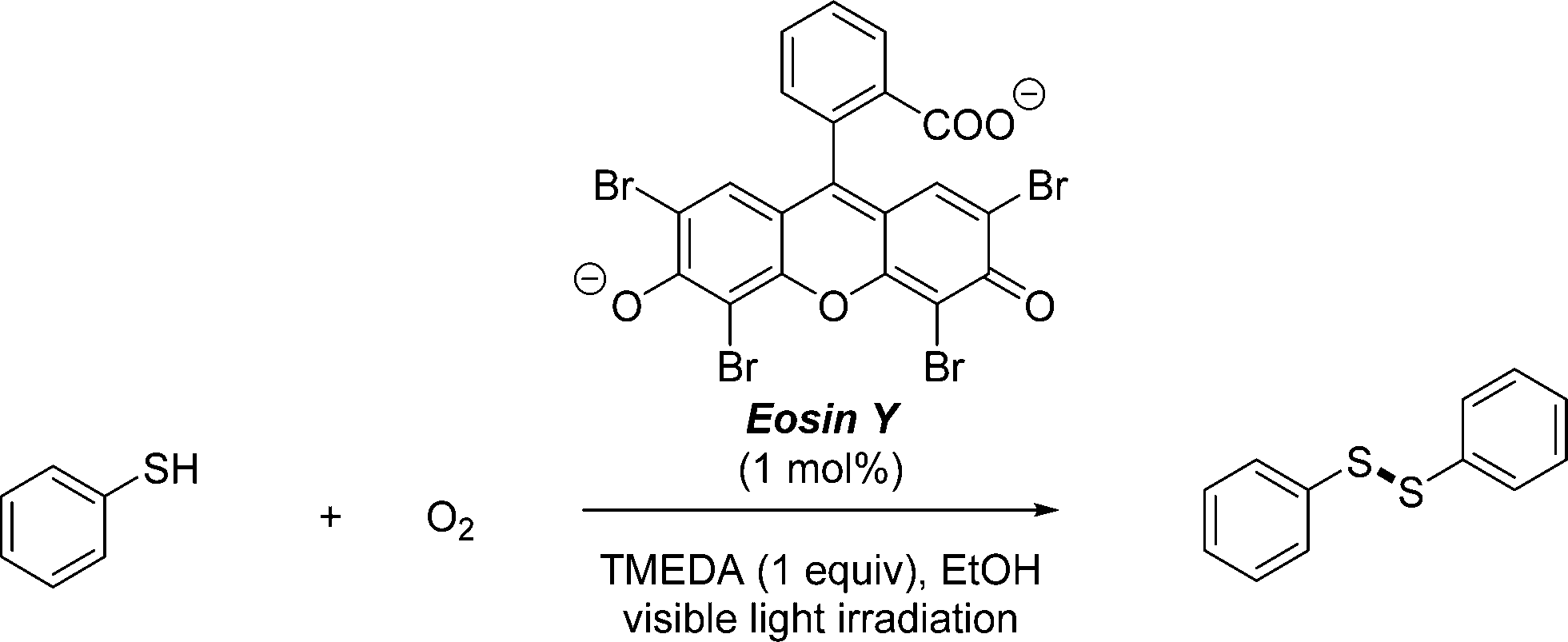
We used the photocatalytic aerobic oxidation of thiols to disulfides as a benchmark reaction to evaluate the efficiency of our multi-capillary photomicroreactor system. Disulfides represent an important class of organic molecules which find applications ranging from pharmaceuticals to rubber vulcanization agents. This reaction was recently developed in our group and allows to convert thiols into their corresponding disulfides under mild reaction conditions (room temperature, visible light irradiation).16,36,37 Eosin Y is used as a cheap and metal-free photocatalyst38 and pure oxygen as the oxidant.39,40 In batch, the reaction requires several hours to reach complete conversion, while in flow the reaction time can be reduced to the minute range. In this study, we use thiophenol as the substrate and ethanol as a cheap and green solvent (Scheme 1).
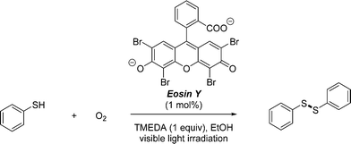 |
| | Scheme 1 Visible light photocatalytic aerobic oxidation of thiophenol to diphenyl disulfide using Eosin Y as a photocatalyst. | |
2.2. Design of multi-capillary photomicroreactor system for gas–liquid photoredox catalysis
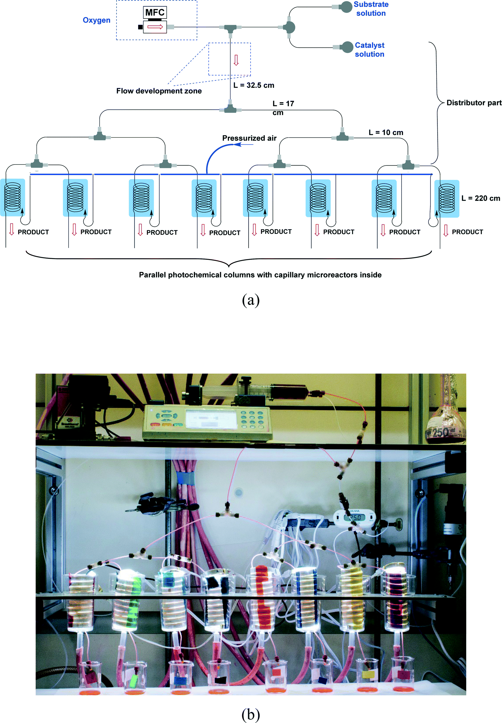
The design of our multi-capillary microreactor system consists mainly of two parts including a distributor section and a series of parallel capillary photomicroreactors (Fig. 1). Key in our design is the use of commercially available parts which would allow other researchers to assemble the system in a cost- and time-efficient fashion. The flow distribution is done by using a series of T-micromixers (PEEK, 1/16′′, IDEX Health & Science, Part No. P-714) as a basic bifurcation configuration (dichotomic tree structure). The flow can be divided subsequently in 2n different photomicroreactors. This strategy allows to gradually scale the photochemistry up and leaves sufficient flexibility to meet a certain demand. The microfluidic connections and the photocapillary were made with high purity perfluoroalkoxy alkane capillaries (PFA, 0.75 mm ID, IDEX Health & Science, Part No. 1622 L). The pressure drop over the distributor could be rapidly adjusted by using back pressure regulators (BPRs, Part No. P-768) or pieces of PFA capillary with a narrow inner diameter (0.25 mm ID, IDEX Health & Science, Part No. 1902 L). The photomicroreactor was constructed by using PFA capillaries (0.50 mm ID, 2.15 m length, 0.95 mL volume, IDEX Health & Science, Part No. 1622 L). A detailed procedure for fabricating individual photomicroreactors can be found in our previous work.16,36,37 Pressurized air was used to keep the reactor at room temperature (22 ± 3 °C, detected by a thermocouple).
 |
| | Fig. 1 (a) Schematic overview of the 8-capillary microreactor system, (b) a picture of the 8-capillary microreactor system with a gas–liquid photocatalytic transformations running. | |
A first syringe was filled with the substrate solution containing 0.5 M thiophenol in ethanol and α,α,α-trifluorotoluene as an internal standard. A second syringe was filled with 1 mol% Eosin Y, 1 equivalent TMEDA and ethanol as the solvent. Both solutions were introduced into the photochemical system with a single syringe pump (Fusion 200 Classic) and merged in a T-micromixer with oxygen, which is controlled by a gas mass flow controller (Bronkhorst), resulting in gas–liquid two-phase flow. The flow rate ratio of the gas to the liquid phase was kept at 3![[thin space (1/6-em)]](https://www.rsc.org/images/entities/char_2009.gif) :1. The flow was subsequently divided over several parallelly placed photochemical capillary microreactors. These capillaries were irradiated with white light-emitting diodes (LEDs). After attaining a steady state, reaction samples were collected and the reaction was quenched with a saturated ammonium chloride (NH4Cl) solution and diluted with ethyl acetate (EtOAc). The samples were purified over a short plug of silica and analyzed with GC-FID in order to obtain the product yield and conversion. The flow distribution characteristics were measured by weighing the different samples from the parallel capillary microreactors over time.
:1. The flow was subsequently divided over several parallelly placed photochemical capillary microreactors. These capillaries were irradiated with white light-emitting diodes (LEDs). After attaining a steady state, reaction samples were collected and the reaction was quenched with a saturated ammonium chloride (NH4Cl) solution and diluted with ethyl acetate (EtOAc). The samples were purified over a short plug of silica and analyzed with GC-FID in order to obtain the product yield and conversion. The flow distribution characteristics were measured by weighing the different samples from the parallel capillary microreactors over time.
3. Results and discussion
3.1. Flow distribution performance without reaction processes
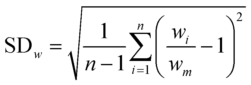
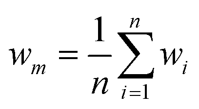
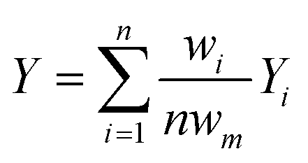
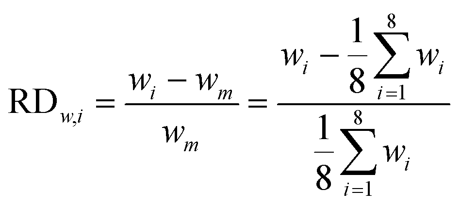
Research on flow splitting with unsymmetrical microscale branches has been conducted in the past.41–43 However, a symmetrical splitting is more relevant for practical applications in chemical reactor engineering and flow chemistry. Hereto, small differences in pressure drop (hydraulic resistance) between the individual branching channels need to be ensured. This leads to an equal flow distribution and thus improved reaction performance. Hydrodynamics studies on gas–liquid two-phase flow splitting with symmetrical branches demonstrated nonetheless that obtaining a good flow distribution is challenging.44,45 Typically, the flow non-uniformity among parallel channels was more than 10%. In this work, to quantify the flow non-uniformity in the 2n-capillary microreactor system, a standard deviation (SDw) is defined between the actual mass flow rate in each capillary (wi) and the average total mass flow rate for all capillaries (wm):| | 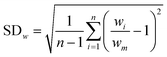 | (1) |
| |  | (2) |
3.1.1. 2-Capillary system.
The formation of Taylor flow (segmented gas–liquid flow or slug flow) can be obtained in a T-micromixer by essentially two strategies, i.e. colliding shearing (Fig. 2a) and perpendicular shearing (Fig. 2b).46 Previous studies on bubble breakup in such T-junctions demonstrated that also the orientation of the splitting unit mattered and thus could influence the flow distribution.42 This Taylor flow reaction stream can be subsequently distributed over the individual photomicroreactors by using another T-micromixer (Fig. 2a and b). Another strategy is to first split the liquid and gas streams individually and then recombine them at the entrance of each photomicroreactor (Fig. 2c).
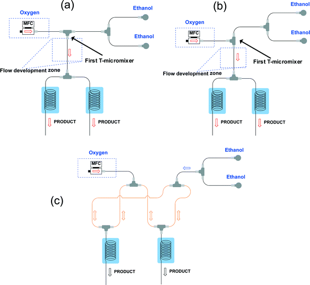 |
| | Fig. 2 Schematic diagram of the 2-capillary microreactor system with (a) colliding shearing or with (b) perpendicular shearing when the gas and liquid phases contact at the first T-micromixer, or (c) with individually splitting of the gas and liquid phases before they contact in the parallel capillaries. | |
The latter system in which the gas and liquid phase were split separately could not ensure a good and stable distribution (Fig. 2c). We observed a flow channeling phenomenon in the loop indicated in orange in Fig. 2c. After enough pressure is build up, the combined liquid/gas stream shoots through one of the photomicroreactors. Therefore, we abandoned this strategy for our numbering-up design.
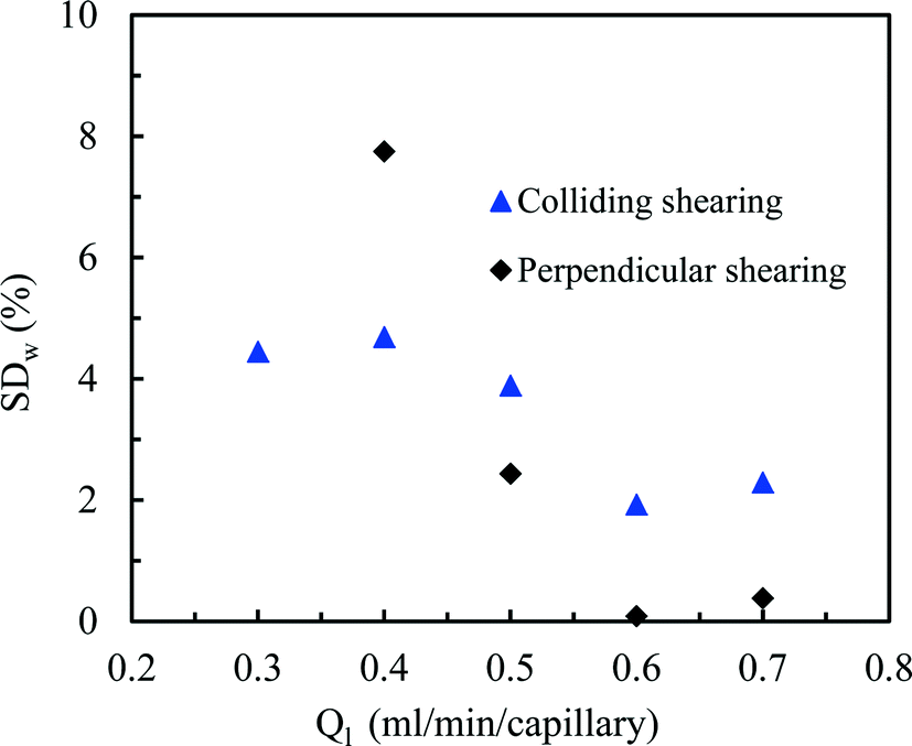
Gratifyingly, a good distribution over the two photomicroreactors could be obtained by first establishing a well-defined Taylor flow which is subsequently distributed over the different photomicroreactors (Fig. 3). Both colliding and perpendicular shearing ensured good flow distribution with a standard deviation below 10% between the mass flow rates through the capillaries compared to the average liquid flow rate (Ql). In particular, the colliding shearing mode gave a more consistent flow distribution with a standard deviation lower than 5% over a broad range of flow rates relevant for the aerobic photocatalytic oxidation of thiols. Importantly, a stable Taylor flow was observed in both capillaries after flow splitting with the colliding shearing mode.47,48 The perpendicular shearing mode provided a larger variation over the flow rate range.
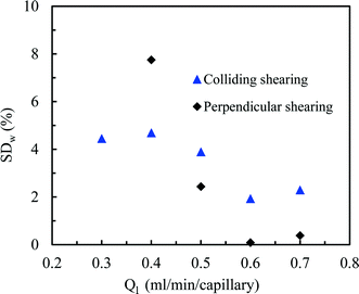 |
| | Fig. 3 Comparison of flow splitting quality between two 2-capillary systems using either colliding shearing or perpendicular shearing for the formation of the gas–liquid segmented flow. | |
3.1.2. 4-Capillary system.
Encouraged by the excellent results for the 2-capillary system, we increased the number of photomicroreactors up to four, which requires a more stringent design of the distributor section. Recently, Schouten et al. proposed a design theory which provided good flow distribution in a multi-channel microreactor system for gas–liquid Taylor flow regimes.49 The authors claimed that the ratio of the pressure drop in the distributor part (ΔPd) to the pressure drop in the reactor channels (ΔPc) played a crucial role to avoid flow maldistribution (eqn (3)). If the relative pressure drop (Δ![[P with combining tilde]](https://www.rsc.org/images/entities/i_char_0050_0303.gif) ) is high enough, i.e. 4–25 in their study, a proper distribution can be obtained with a flow non-uniformity below 10%.
) is high enough, i.e. 4–25 in their study, a proper distribution can be obtained with a flow non-uniformity below 10%.| |  | (3) |
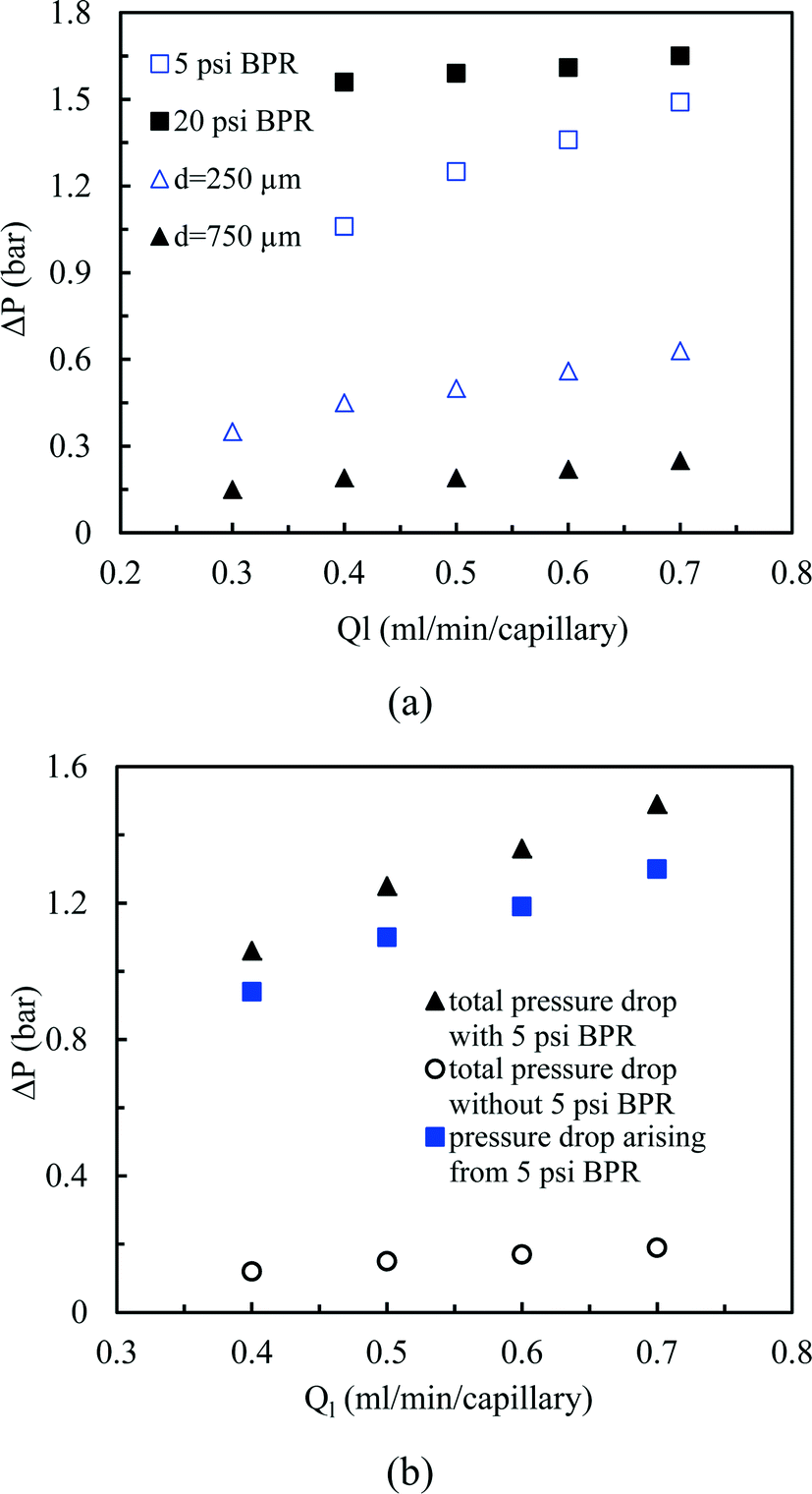
According to this principle, pressure adjustment in different parts of a multi-capillary microreactor system would strongly affect the flow distribution performance. In our design, back pressure regulators and a narrow capillary (250 μm inner diameter d and 33 cm length) were evaluated to increase the resistance in the distributor part. As shown in Fig. 4, both the back pressure regulators and the narrow diameter capillary could provide an excellent flow distribution with SDw < 5% at high average liquid flow rates (e.g. 0.6 and 0.7 ml per min per capillary), indicating the feasibility of this novel strategy for the numbering-up of capillary microreactors. For low flow rates, a higher SDw was observed with the capillary approach, however, the difference between the 750 μm and the 250 μm at 0.4 mL per min per capillary was pronounced. These findings indeed demonstrate that the additional resistance in the distributor part and a proper pressure adjustment are beneficial for obtaining excellent flow uniformity for parallel capillary microreactors in a branching numbering-up lay-out.
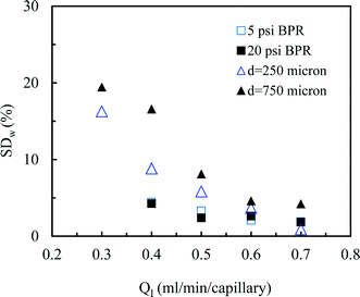 |
| | Fig. 4 Effect of the constriction in the distributor section on the flow distribution: use of back pressure regulators (BPR) or capillaries. | |
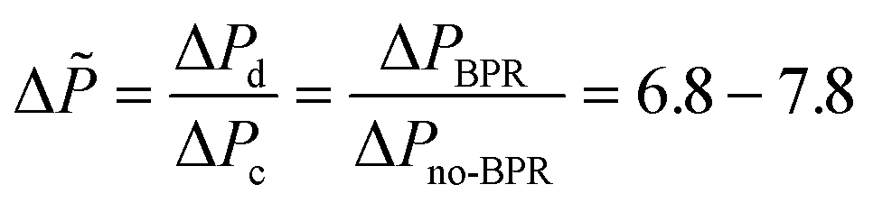
Next, we measured the pressure drop in the 4-capillary system in order to further verify the validity of the Schouten principle for flow distribution (eqn (3)). As can be seen from Fig. 5a, the use of a BPR or a smaller capillary in the distributor part largely increased the pressure drop in the multi-capillary system. The pressure drop difference between the cases with and without a BPR can be considered as the additional pressure drop arising from the BPR (Fig. 5b). It is reasonable to assume that this local pressure drop is equal to the total pressure drop in the distributor part (ΔPd). The pressure drop in the absence of a BPR (ΔPno-BPR) can be considered as the total pressure drop in the capillary microreactors (ΔPc). Consequently, the following equation can be obtained for the 4-capillary microreactor system:
| |  | (4) |
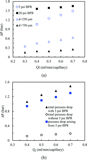 |
| | Fig. 5 (a) Pressure drop in the 4-capillary system with different constrictions in the flow development zone, (b) pressure drop characteristics in the 4-capillary system with the 5 psi BPR. | |
The value obtained for our system is around 7–8 which proves the rationality and usefulness of the theoretical principle made by Schouten
et al. for the design of numbered-up gas–liquid microreactors.
49
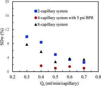
3.1.3. 8-Capillary system.
Next, we designed an 8-capillary system as shown in Fig. 1, which allows us to scale our photocatalytic processes in total eight times. A comparison of the flow distribution performance between this 8-capillary system and the 2- and 4-capillary systems was made for different flow rates (Fig. 6). Encouragingly, the 8-capillary system showed a similar flow distribution performance as the 2- and 4-capillary systems. The values of SDw for flow splitting were lower than 5%, except for the relative low average liquid flow rate (0.3 ml per min per capillary). Notably, the flow pattern in the development zone of the distributor section was annular flow or slug-annular flow when the volumetric flow rates of gas–liquid two phases became large enough. This is evident as the superficial velocity is 8 times higher than in a single photomicroreactor device. In addition, the local pressure drop due to the flow splitting at the junctions of T-micromixers nonlinearly increased with the increasing volumetric flow rates of gas–liquid two phases.50 Further, the pressure drop becomes much higher due to the flow pattern transition from slug flow to annular flow. This provides sufficient additional resistance which makes the use of an additional BPR superfluous. All these aspects contributed to the excellent flow uniformity for the parallel capillaries in the 8-capillary system.
 |
| | Fig. 6 Flow distribution characteristics in the 2-capillary system, the 4-capillary system with a 5 psi BPR and the 8-capillary system. | |
The flow distribution in the 8-capillary system at a low average liquid flow rate of 0.3 ml per min per capillary was worse than in the other numbered-up systems. Song et al. revealed that the evolution of a gas–liquid interface at a T-junction, by the breakup of liquid plugs or gas bubbles, is dependent on nonlinear characteristics.51 This is attributed to the interplay between the dynamical pressure and the geometrically controlled threshold value in a multi-stage branching tree. At low flow rates, the flow instability increased as the number of bifurcation generations increases, leading to a deteriorated flow distribution in multi-capillary microreactor systems with T-micromixers as splitting units. Similar to our observations, Song et al. reported that the flow distribution improves with increasing flow rates.
3.2. Numbering-up of capillary microreactors for photocatalytic processes
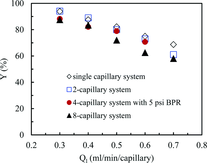
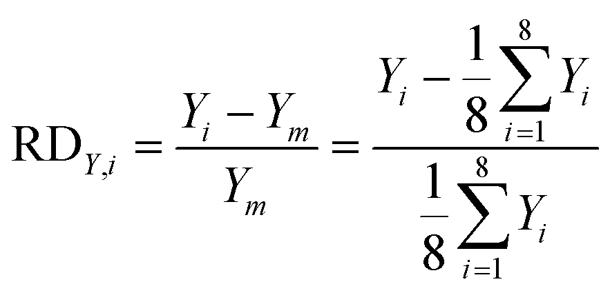
So far we observed an excellent performance of our numbering-up strategy in the absence of any chemical reaction. However, the real challenge is to use this system for a chemical reaction in which the gaseous compound is consumed. Hereto, we have selected the aerobic photocatalytic oxidation of thiols to disulfides with Eosin Y as a photocatalyst. Small differences in reactivity within different channels should result in a different consumption of the oxygen gas leading to rather large changes of the hydrodynamics. Consequently, large differences in yield should be observed in the individual channels. In our numbering-up system, the reaction mixture exiting from every channel can be separately analyzed. This strategy provide us an important tool to assess the effectiveness of the numbering-up design. In this section, we compare the efficiency of the single capillary system with the optimal multi-capillary microreactor systems, including the 2-capillary system, the 4-capillary system with a 5 psi BPR and the 8-capillary system.
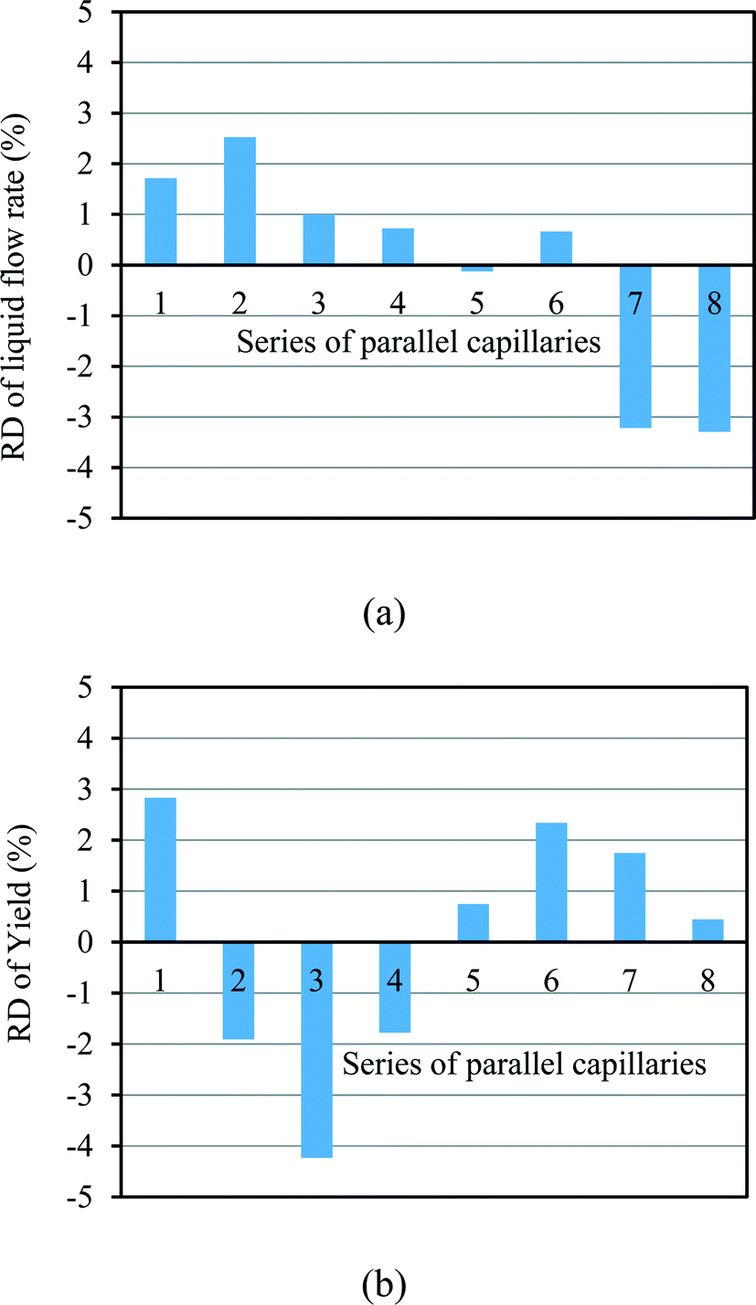
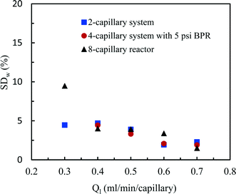
3.2.1. Flow distribution performance in the presence of a photocatalytic gas–liquid reaction.
Fig. 7 gives an overview of the flow distribution in our numbered-up system in the presence of the photocatalytic aerobic oxidation reaction. Even in the presence of this demanding reaction, the flow distribution is still excellent with SDw < 10%. These values are only slightly worse than in the non-reactive system. The higher SDw in the presence of a chemical reaction can be attributed to the quick consumption of oxygen, which changes the gas–liquid interface. This changing gas–liquid interface subsequently changes the capillary pressure drop and thus results in fluctuations and in flow instabilities.52
 |
| | Fig. 7 Flow distribution characteristics in the 2-capillary system, the 4-capillary system with 5 psi BPR and the 8-capillary system during a photocatalytic reaction. | |
4. Conclusion
Here, we developed a new and convenient approach for the numbering-up of capillary microreactors. Only cheap and commercially available parts were used for the assembly of the system making it readily accessible to others in academia and industry. A branching splitting strategy was chosen utilizing cheap T-micromixers. The flexibility of our numbering-up assembly allowed us to gradually scale gas–liquid segmented flow 2n times (n = 0, 1, 2, 3). First, we have assessed the flow distribution performance in the absence of a chemical reaction. Low standard deviations (SDw < 5%) were observed for a broad range of flow rates. Interestingly, we observed that the pressure drop over the distributor was important to ensure a good distribution over the different capillary microreactors. Next, we applied our system to the scale-up of the aerobic photocatalytic oxidation of thiols to disulfides. Again, excellent flow distribution was observed (SDw < 10%). The somewhat higher standard deviation can be attributed to the fast consumption of the gas phase under these photocatalytic reaction conditions. The yield of the numbered-up photomicroreactors was comparable to the yield obtained in a single photomicroreactor device and demonstrated the efficiency of our system. We anticipate that our results and the design of our numbered-up photomicroreactors will find broad application in academia and industry. In this paper, we focused on gas–liquid photocatalytic reactions but the design should be amenable towards homogeneous and liquid–liquid photochemical reactions as well. Currently, we are pursuing these goals in our laboratory. We believe that also a higher scalability should be feasible with this strategy (2n where n > 3), however, this will require a careful adjustment of the pumping system and the distributor section as the pressure drop will increase substantially in such numbered-up systems.
Acknowledgements
Y. S. would like to thank the European Union for a Marie Curie – Intra-European Fellowship (No. 622415). T. N. would like to acknowledge financial support from the Dutch Science Foundation for a VENI Grant (No. 12464) and from the European Union for a Marie Curie CIG Grant (Grant No. 333659).
References
- H. D. Roth, Angew. Chem., Int. Ed. Engl., 1989, 28, 1193–1207 CrossRef.
- N. Hoffmann, Chem. Rev., 2008, 108, 1052–1103 CrossRef CAS PubMed.
- S. Chatani, C. J. Kloxin and C. N. Bowman, Polym. Chem., 2014, 5, 2187–2201 RSC.
- T. Bach and J. P. Hehn, Angew. Chem., Int. Ed., 2011, 50, 1000–1045 CrossRef CAS PubMed.
- C. K. Prier, D. A. Rankic and D. W. C. MacMillan, Chem. Rev., 2013, 113, 5322–5363 CrossRef CAS PubMed.
- S. Fukuzumi and K. Ohkubo, Org. Biomol. Chem., 2014, 12, 6059–6071 CAS.
- A. E. Cassano, C. A. Martin, R. J. Brandi and O. M. Alfano, Ind. Eng. Chem. Res., 1995, 34, 2155–2201 CrossRef CAS.
- J. Colina-Marquez, F. Machuca-Martinez and G. L. Puma, Environ. Sci. Technol., 2010, 44, 5112–5120 CrossRef CAS PubMed.
- S. Ghafoori, M. Mehrvar and P. K. Chan, Chem. Eng. J., 2014, 245, 133–142 CrossRef CAS.
- A. K. Suresh, M. M. Sharma and T. Sridhar, Ind. Eng. Chem. Res., 2000, 39, 3958–3997 CrossRef CAS.
- D. S. Meyaard, Q. F. Shan, J. Cho, E. F. Schubert, S. H. Han, M. H. Kim, C. Sone, S. J. Oh and J. K. Kim, Appl. Phys. Lett., 2012, 100 Search PubMed.
- Y. H. Su, N. J. W. Straathof, V. Hessel and T. Noël, Chem. – Eur. J., 2014, 20, 10562–10589 CrossRef CAS PubMed.
- J. P. Knowles, L. D. Elliott and K. I. Booker-Milburn, Beilstein J. Org. Chem., 2012, 8, 2025–2052 CrossRef CAS PubMed.
- E. E. Coyle and M. Oelgemoller, Photochem. Photobiol. Sci., 2008, 7, 1313–1322 CAS.
- T. Noël, X. Wang and V. Hessel, Chim. Oggi Chem., 2013, 31, 10–14 Search PubMed.
- Y. Su, V. Hessel and T. Noël, AIChE J., 2015, 61, 2215–2227 CrossRef CAS.
- K. G. Maskill, J. P. Knowles, L. D. Elliott, R. W. Alder and K. I. Booker-Milburn, Angew. Chem., Int. Ed., 2013, 52, 1499–1502 CrossRef CAS PubMed.
- N. J. W. Straathof, H. P. L. Gemoets, X. Wang, J. C. Schouten, V. Hessel and T. Noël, ChemSusChem, 2014, 7, 1612–1617 CrossRef CAS PubMed.
- N. Straathof, D. Osch, A. Schouten, X. Wang, J. Schouten, V. Hessel and T. Noël, J. Flow Chem., 2014, 4, 12–17 CrossRef CAS.
- N. J. W. Straathof, B. J. P. Tegelbeckers, V. Hessel, X. Wang and T. Noël, Chem. Sci., 2014, 5, 4768–4773 RSC.
- S. Meyer, D. Tietze, S. Rau, B. Schaefer and G. Kreisel, J. Photochem. Photobiol., A, 2007, 186, 248–253 CrossRef CAS.
- F. Lévesque and P. H. Seeberger, Angew. Chem., Int. Ed., 2012, 51, 1706–1709 CrossRef PubMed.
- T. S. A. Heugebaert, C. V. Stevens and C. O. Kappe, ChemSusChem, 2015, 8, 1648–1651 CrossRef CAS PubMed.
- A. Tonkovich, D. Kuhlmann, A. Rogers, J. McDaniel, S. Fitzgerald, R. Arora and T. Yuschak, Chem. Eng. Res. Des., 2005, 83, 634–639 CrossRef CAS.
- R. Schenk, V. Hessel, C. Hofmann, H. Lowe and F. Schonfeld, Chem. Eng. Technol., 2003, 26, 1271–1280 CrossRef CAS.
- N. de Mas, A. Gunther, T. Kraus, M. A. Schmidt and K. F. Jensen, Ind. Eng. Chem. Res., 2005, 44, 8997–9013 CrossRef CAS.
- Y. H. Su, A. Lautenschleger, G. W. Chen and E. Y. Kenig, Ind. Eng. Chem. Res., 2014, 53, 390–401 CrossRef CAS.
- K. Wang, Y. C. Lu and G. S. Luo, Chem. Eng. Technol., 2014, 37, 2116–2122 CrossRef CAS.
- R. Schenk, V. Hessel, C. Hofmann, J. Kiss, H. Lowe and A. Ziogas, Chem. Eng. J., 2004, 101, 421–429 CrossRef CAS.
- A. Yavorskyy, O. Shvydkiv, N. Hoffmann, K. Nolan and M. Oelgemoller, Org. Lett., 2012, 14, 4342–4345 CrossRef CAS PubMed.
- M. Al-Rawashdeh, J. Zalucky, C. Muller, T. A. Nijhuis, V. Hessel and J. C. Schouten, Ind. Eng. Chem. Res., 2013, 52, 11516–11526 CrossRef CAS.
- R. D. Chambers, M. A. Fox, D. Holling, T. Nakano, T. Okazoe and G. Sandford, Lab Chip, 2005, 5, 191–198 RSC.
- T. Iwasaki, N. Kawano and J. Yoshida, Org. Process Res. Dev., 2006, 10, 1126–1131 CrossRef CAS.
- K. S. Elvira, R. C. R. Wootton, N. M. Reis, M. R. Mackley and A. J. DeMello, ACS Sustainable Chem. Eng., 2013, 1, 209–213 CrossRef CAS.
- N. M. Reis and G. Li Puma, Chem. Commun., 2015, 51, 8414–8417 RSC.
- A. Talla, B. Driessen, N. J. W. Straathof, L. G. Milroy, L. Brunsveld, V. Hessel and T. Noel, Adv. Synth. Catal., 2015, 357, 2180–2186 CrossRef CAS.
- Y. Su, A. Talla, V. Hessel and T. Noël, Chem. Eng. Technol., 2015, 38, 1733–1742 CrossRef CAS.
- D. P. Hari and B. Konig, Chem. Commun., 2014, 50, 6688–6699 RSC.
- H. P. L. Gemoets, Y. Su, M. Shang, V. Hessel, R. Luque and T. Noël, Chem. Soc. Rev., 2015 10.1039/C5CS00447K.
- B. Pieber and C. O. Kappe, Top. Organomet. Chem., 2015 DOI:10.1007/3418_2015_133.
- J. F. Chen, S. F. Wang, H. F. Me, S. H. Cai and Y. Zhao, Chem. Eng. Sci., 2013, 104, 881–890 CrossRef CAS.
- T. Fu and Y. Ma, Chem. Eng. Sci., 2015, 135, 343–372 CrossRef CAS.
- S. Kim and S. Y. Lee, Chem. Eng. Sci., 2015, 134, 119–128 CrossRef CAS.
- M. Al-Rawashdeh, L. J. M. Fluitsma, T. A. Nijhuis, E. V. Rebrov, V. Hessel and J. C. Schouten, Chem. Eng. J., 2012, 181, 549–556 CrossRef.
- J. Yue, R. Boichot, L. G. Luo, Y. Gonthier, G. W. Chen and Q. Yuan, AIChE J., 2010, 56, 298–317 CAS.
- C. X. Zhao and A. P. J. Middelberg, Chem. Eng. Sci., 2011, 66, 1394–1411 CrossRef CAS.
- P. Rapolu and S. Y. Son, Exp. Fluids, 2011, 51, 1101–1108 CrossRef CAS.
- S. K. Yap, Y. Yuan, L. Zheng, W. K. Wong, N. Yan and S. A. Khan, J. Flow Chem., 2014, 4, 200–205 CrossRef.
- M. Al-Rawashdeh, X. Nijhuis, E. V. Rebrov, V. Hessel and J. C. Schouten, AIChE J., 2012, 58, 3482–3493 CrossRef CAS.
- Y. H. Su, G. W. Chen and E. Y. Kenig, Lab Chip, 2015, 15, 179–187 RSC.
- Y. Song, P. Manneville and C. N. Baroud, Phys. Rev. Lett., 2010, 105 Search PubMed.
- T. T. Fu, Y. G. Ma and H. Z. Li, AIChE J., 2014, 60, 1920–1929 CrossRef CAS.
Footnote |
| † Electronic supplementary information (ESI) available. See DOI: 10.1039/c5re00021a |
|
| This journal is © The Royal Society of Chemistry 2016 |
Click here to see how this site uses Cookies. View our privacy policy here.