Design and fabrication of graphene fibers based on intermolecular forces and charge properties in a novel acidic system

Zhaofa Zhanga, Desuo Zhang*ab, Hong Lina and Yuyue Chen*a
aNational Engineering Laboratory for Modern Silk, College of Textile and Clothing Engineering, Soochow University, Suzhou 215123, P. R. China
bNantong Textile & Silk Industrial Technology Research Institute, Nantong 226004, P. R. China. E-mail: dszhang@suda.edu.cn; chenyy@suda.edu.cn

Received 29th September 2016 , Accepted 7th October 2016

First published on 10th October 2016


Abstract

Graphene is one of the most famous carbon-based materials. Integrating two dimension (2D) graphene nanoflakes to macroscopic one dimension (1D) fibers could enrich graphene-based materials and its applications. This paper describes a new strategy of fabricating macroscopic graphene oxide fibers based on intermolecular forces and their charge properties in a new acidic coagulation system. The formation mechanism of graphene oxide fibers was proposed. The graphene fibers were prepared by following chemical reduction. The resultant graphene fibers have strong strain of 107.9 MPa and outstanding electrochemical properties. The cyclic voltammetry and galvanostatic charge–discharge studies for graphene fibers exhibited typical capacitive behavior with good rate stability. This work extended the methods for preparation of graphene fibers. The prepared macroscopic 1D graphene fibers may have a wide range of applications such as supercapacitors, sensors, smart and conductive textiles, etc.

Introduction

Graphene, a two-dimension (2D) monolayer of sp2-hybridized carbon atoms tightly packed into a honeycomb lattice, has attracted persistent attention from the whole world since its discovery in 2004.1 As the thinnest material ever discovered and the basic unit of carbon materials, including fullerene, carbon nanotubes, graphite nanoplatelets,2,3 it has excellent properties, such as immense electron mobility,4 high thermal conductivity,5 the strongest mechanical strength.6–8 Thus many effects and great progress had focused on integrating those outstanding properties to macroscopic materials, like conductive papers, graphene films,9,10 3D structure materials,11,12 especially one dimension (1D) macroscopic fibers.13–15 However, design and fabrication of the macroscopic fibers using pure graphene nanosheets was still challengeable due to the nano-size of graphene and no feasible methods. Furthermore, the limited dispersity of graphene in common solvents7 hinders its direct assembling and applications. However, graphene oxide can dissolves in common solvents and overcome the above mentioned shortcoming owing to many oxygen functional groups, like carboxylic acid groups, epoxy and hydroxyl groups,7 on the edge of graphene oxide. In addition, graphite as the raw material for preparation of grapheme oxide was rich and inexpensive and the method for the preparation of graphene oxide was convenient and feasible. Thus, graphene oxide was commonly used as precursor to prepare graphene on a large-scale and the macroscopic functional materials for a wide range of applications.16–18

Recently, several groups used graphene oxide suspensions as precursors to prepare macroscopic fibers. Gao and his group prepared graphene oxide fibers in alkalescent coagulation bath and then used chemical reduction method to achieve graphene fibers.19 In coagulating process, the alkali particles were wrapped in the folds of the fibers along with the shrinking, which were difficult to be clearly cleaned. Meanwhile, the color of graphene oxide fiber changed from brown to black as the result of reduction reaction.20–22 Furthermore, the flexibility of graphene fiber was slightly weakened. Yu and his fellows use cetyltrimethyl ammonium bromide (CTAB) as surfactant to improve the fiber-forming property.14 Zhu and her partners firstly mixed graphene oxide suspensions with sodium deoxycholate (NaDC) and then spun the mixture into ethanol. NaDC dissolved in ethanol and graphene oxide suspensions assembled to form fibers.23 Using surfactant and adding NaDC into graphene oxide suspension were all to achieve the purpose of improving the fiber-forming performance, but also introducing impurities to graphene oxide fibers, which was difficult to be completely removed. Xu and his team found that graphene oxide can self-assemble to nano-fibers at the liquid/air interface.13 But the formation of nano-fiber not only cost a lot of time, but it was also difficult to be collected and applied. As we all know, strong acids, like sulfuric acid, nitric acid and phosphoric acid, are indispensable in Hummers' method to prepare graphene oxide. At the same time, graphene oxide was very sensitive to the charge and acid–base21,24–26 properties of solutions. The acidic reducing agents,17,18 like hydriodic acid (HI),27 were commonly used to reduce graphene oxide to achieve graphene. As far as we know, there is no report about preparing macroscopic graphene oxide fibers and graphene fibers all in acidic system.

In this research, a facile method was proposed to largely prepare macroscopic and neat graphene oxide fibers and graphene fibers in acidic system including acidic coagulation bath system and acidic reduction agent based on intermolecular forces and charge properties. The mechanism of fiber-formation was studied and analyzed. Acetic acid and ethanol were chosen to constitute the acidic coagulation bath, because they can rapidly and clearly evaporated when the fibers went through heat system without repeatedly washing. Macroscopic 1D graphene oxide fibers were continuously spun into acidic coagulation bath, following by drying system, and then directly winded onto tube. After reduction, the as-prepared graphene fibers have good mechanical strength (∼107.9 MPa), extraordinary capacitance and outstanding rate stability. This work paves a new way for mass production of macroscopic graphene fibers with desirable functionalities and morphologies for many applications such as supercapacitors, sensors, smart and conductive textiles, etc.

Experimental section

Materials

Preparation of graphene oxide. Graphene oxide was prepared by Hummers' method.28 Then the brown solution was firstly filtrated and dissolved in the mass fraction of 3% aqueous hydrochloric acid (HCl). These processes were repeated several times. After that, the light brown solution was centrifuged at the speed of 2000 rpm to remove the sediment, which was not completely oxidized graphite. The liquid supernatant was fully stirred before being centrifuged at the speed of 12[thin space (1/6-em)]000 rpm. Then the sediment was slowly evaporated at 40 °C for hours to prepare spinning solution, which was about 20 mg ml−1.
Preparation of graphene oxide fiber. The above mentioned spinning solution was loaded into 10 ml glass syringe. Spinning solution was directly spun into the coagulation bath. Coagulation bath is composed of ethanol and acetic acid with a volume ratio of 4[thin space (1/6-em)]:[thin space (1/6-em)]1. The spun speed was 0.5 ml h−1 in this work. Then the produced graphene oxide fibers coagulated for 10 min following by drying process. Finally, the graphene oxide fiber was directly winded onto rube.
Preparation of graphene fiber. Graphene fibers were prepared by chemical reduction of graphene oxide fibers using HI at 80 °C for 8 h. After reduction, the graphene fibers were washed by ethanol and deionized water for several times to remove the remained HI and then dried at 80 °C for 1 h.

Results and discussion

Wet-spinning of macroscopic graphene oxide fiber

The initially prepared graphene oxide solution was brown and well dispersed. The thin graphene oxide nano-flakes dispersed in the solution were about 1 nm as presented in Fig. 1a and b. In order to get the required concentration of spinning solution, as-prepared graphene oxide solution were centrifuged with the speed of 12[thin space (1/6-em)]000 rpm and slowly evaporated at 40 °C for hours. Fig. 2a shows a schematic illustration of wet-spinning process of fabricating graphene oxide fibers. Graphene oxide solution of about 20 mg ml−1 was loaded into the syringe and flow pump was used to control flow rate at 0.5 ml h−1. Graphene oxide suspensions was injected into the acidic coagulation bath, which composed of ethanol and acetic acid with a volume ratio of 4[thin space (1/6-em)]:[thin space (1/6-em)]1, to form macroscopic graphene oxide fibers. In coagulation bath, primary fibers kept a cylindrical shape and gradually shrunk. Drafted from coagulation bath and followed by drying process, wet graphene oxide fibers immediately turned into dried graphene oxide fibers. And coagulation bath and water in the graphene oxide layers instantly evaporated. In this process, along with the gradually narrowed-distance between graphene oxide nanoflakes, initial graphene oxide fibers shrunk and formed the surface morphology with randomly wrinkles as Fig. 2a(6) demonstrated and Fig. 4a–c confirmed. Graphene oxide fiber was directly winded onto the tube as Fig. 2b showed. And Fig. 2b also illustrated that graphene oxide fibers had good flexibility and bending performance. Using the above mentioned method, macroscopic 1D graphene oxide fibers can be continuously and largely prepared, as Fig. 2c showed the length of a single graphene oxide fiber was more than 100 cm.
image file: c6ra24261h-f1.tif
Fig. 1 AFM image of the initial graphene oxide dispersion on mica wafer (a) and the corresponding height profile (b).

image file: c6ra24261h-f2.tif
Fig. 2 (a) Schematic illustration of wet-spinning process ((1) flow control system, (2) coagulation bath, (3) drying system, (4) winding system, (5) spinning hole and primary graphene oxide fiber, (6) the illustration of graphene oxide fiber after drying), (b) and (c) digital photographs of dried graphene oxide fibers.

The formation mechanism of graphene oxide fiber in acidic coagulation bath system

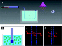
Acidic coagulation bath was essential in the process of forming graphene oxide fibers. The pH value of coagulation bath was about 2.22. Due to the ionization, the zeta potential value of the acidic coagulation bath was 12.8 mV, which means the acidic coagulation bath was positive charged as Fig. 3a displayed. Meanwhile, nanosheets of graphene oxide was highly negative charged in water,29 as the result of the ionization of carboxyl groups and phenolic hydroxyl groups.30 The electrostatic repulsion (ER) of negative charged graphene oxide nanosheets was larger than van der Waals' force (VDW) of nanoflakes,31,32 so it can stably disperse in common solvents. When the solution of negative charged graphene oxide ejected into the positive charged coagulation bath, positive charges would neutralize with negative charges on the surface of initial spun graphene oxide fiber. At the same time, due to the neutralization reaction, the electrostatic repulsion force (ER) was obviously reduced and the van der Waals' force (VDW) was apparently increased. Meanwhile, the distance between graphene oxide nanosheets on the surface became smaller after neutralization reaction as illustrated in Fig. 3b and c. In addition, the carboxyl groups and phenolic hydroxyl groups were mainly on the periphery of the basal plane of graphene oxide during the oxidation process33 and the nanoflakes would gradually shrink. Because the primary neutralization reaction takes place on the surface of graphene oxide fiber, the fiber forms a skin–core structure. This kind of skin–core structure refers to that, nanosheets on the surface of the fiber shrunk and the core of the fiber slightly shrunk without chemical reaction occurring. Due to the skin–core structure, the prepared fibers can be stably existed in the coagulation bath and can be directly pulled out and then go through the drying process. In summary, during coagulation process, nanoflakes on the surface of the spun graphene oxide fiber gradually shrunk owing to the neutralization reaction. Beyond those, in drying process, with the evaporation of coagulation bath and the solution in the layer of nanosheets, the prepared graphene oxide fibers strongly shrunk and became thinner and formed many orderly grooves were along the fiber axis direction.
image file: c6ra24261h-f3.tif
Fig. 3 The coagulation process of graphene oxide fiber. (a) The schematic image of acidic coagulation bath, (b and c) the schematic images of the forces of graphene nanosheets before and after coagulation.

Characterization of graphene oxide fiber and graphene fiber

To observe the morphology of prepared graphene oxide fibers, scanning electron microscope (SEM) measurements were carried out to reveal the characteristics of their microstructures. Obviously, many orderly grooves were along the fiber axis direction as Fig. 4a–c showed. Grooves, which contributed to the flexible property of macroscopic fiber,34,35 were formed in coagulating and drying process. In coagulating process, graphene oxide nanoflakes gradually assembled and shrunk. Furthermore, in drying process, graphene oxide nanoflakes rapidly shrunk along with the evaporation of coagulation bath and water between the graphene oxide layers. The diameter of graphene oxide fiber was uniform and about 100 μm as SEM images exhibited in Fig. 4a–c. Graphene oxide fiber demonstrated a layer-by-layer structure in cross-section as showed in Fig. 4d–f. Owing to the layer-by-layer structure, the microstructure of graphene oxide fiber was dense and intact.
image file: c6ra24261h-f4.tif
Fig. 4 (a)–(c) Scanning electron microscope (SEM) images of the morphology of graphene oxide fibers, (d)–(f) the cross-section of graphene oxide fibers with different magnification.

In order to achieve graphene fiber, graphene oxide fiber was chemical reduced by HI at 80 °C for 8 h. After reduction, the microscopic morphology of graphene fiber had no difference to graphene oxide fibers confirmed by SEM images as Fig. 5a and b showed. Besides, the diameter of graphene did not change, which proved that prepared graphene fiber had compact structure coinciding with the cross-section images in Fig. 4d–f. In chemical reduction process, oxygen-containing functional groups, like hydroxyl and epoxy groups were eliminated confirming by X-ray photoelectron spectroscopy (XPS) in Fig. 6a and b. In XPS spectra, four peaks centered at 284.8, 286.6, 288.3 and 289 eV were assigned to C–C/C[double bond, length as m-dash]C in aromatic rings, C–O (epoxy), carbonyl (C[double bond, length as m-dash]O), and carboxyl acid groups (COOH),36–38 respectively. In comparison, the peak at 284.8 eV sharply stronger from graphene oxide fibers to graphene fibers following with the fading of peak at 286.6, and 289 eV, verifying the removal of oxygen functional groups and the restoration of conjugated network.17,39 High effectiveness of the reduction of graphene oxide fibers (GO-F) to graphene fibers (G-F) was also confirmed by the Raman spectra from Fig. 6c. The D-band was quite intense after reduction, and the value of intensity ratio of D-band (1331 cm−1) to G-band (1567 cm−1) raises from 1.01 for GO-F to 1.16 for G-F, indicating the degree of disorder and the average of the sp2 domains.23,40,41 In addition, the 2D band of at 2683 cm−1 in Raman spectra is strengthen after reduction, revealing the restoration of sp2 carbon and the decrease of sp3 carbon detects.23 This ratio raised, because graphene oxide flakes disorderly accumulated to form fiber in wet-spinning process. After reduction, oxygen groups were almost removed and sp2 carbon in graphene significantly increased.7,16,40


image file: c6ra24261h-f5.tif
Fig. 5 (a) and (b) Scanning electron microscope (SEM) images of the morphology of graphene fibers.

image file: c6ra24261h-f6.tif
Fig. 6 XPS spectra of graphene oxide fiber (a) and graphene fiber (b), Raman spectra of graphene oxide fibers (GO-F) and graphene fibers (G-F) (c).

Mechanical and electrochemical properties of GO-F and G-F

Mechanical tensile measurements demonstrated that both GO-F and G-F exhibited typical plastic deformation under tensile loading at room temperature as showed in Fig. 7. The tensile strength of the individual GO-F were 73.5 MPa. The corresponding elongation of GO-F was 5.6%. After reduction, the intensity of graphene fibers had increased to 107.9 MPa. However, the elongation of G-F decreased to 3.5%. The superior strength probably caused by smaller interlayer spacing after reduction.42,43
image file: c6ra24261h-f7.tif
Fig. 7 The strength of GO-F and G-F.

To investigate its electrochemical properties, G-F was directly used as working electrode by the method of three-electrode system. A platinum and Hg/HgO were respectively used as the counter and reference electrodes. The electrolyte was 1 M Na2SO4 solution. Fig. 8a illustrated the cyclic voltammetry (CV) cures of G-F at scan rate 10–500 mV s−1. The CV cures were in the shape of distorted rectangular with no peak generated by faradic current, which demonstrated G-F had ideal capacitive behaviour.44–46 The galvanostatic charge–discharge cycles with a current density of 30–50 μA were used to test the rate stability of G-F electrodes, as shown in Fig. 8b. All cures were in the shape of equilateral triangle, which indicated good reversibility.44 The specific capacitance (Cs) were calculated by using the slope of the discharge curves with different current was 4.3 mF cm−2 at 30 μA and 2.5 mF cm−2 at 50 μA respectively, which were much higher than previous reported values.44,45 The cylindrical surface area was calculated by formula (1):

 
S = 2πRL (1)
where R was the radius of the fiber and L was the length of the fiber.


image file: c6ra24261h-f8.tif
Fig. 8 Electrochemical characterization. (a) CV cures of G-F at scan rate from 10 to 500 mV s−1 and (b) galvanostatic charge–discharge cycles of G-F at 30–50 μA cm−2.

Conclusion

In summary, macroscopic GO-F and G-F were prepared by intermolecular forces and charge properties in a new acidic system, containing acidic coagulation bath system and acidic reduction agent. In addition, the formation mechanism of GO-F in acidic bath was proposed. Negative charged graphene oxide nanoflakes were neutralized with positive charged hydrogen ion during the coagulation process. At the same time, during the drying process, graphene oxide nanoflakes shrunk seriously and stacked layer by layer. Furthermore, G-F has strong intensity after reduction. Besides, G-F was directly used as electrode, demonstrating extraordinary capacitance and outstanding stability.

Instruments

Atomic force microscopy images were taken in the tapping mode by carrying out on a Multimode & Bioscope, with samples prepared by spin-coating graphene oxide dispersions onto freshly cleaved mica substrates at 1000 rpm. SEM images were taken on a Hitachi S4800 field-emission SEM system. X-ray photoelectron spectroscopy (XPS) measurements were analyzed by an ESCALAB 250. Raman spectra were recorded using a LabRamHR. The laser excitation was provided by a regular model laser operating at 514.5 nm. Mechanical property tests of as-prepared products were conducted with an Instron material testing system (Instron 3365) at a strain rate of 10 mm min−1. The electrochemical characterization was carried out in a standard three-electrode system with platinum as the counter electrode and Hg/HgO as the reference electrode. The electro-chemical performance was characterized using a CHI 660B electrochemical workstation (Shanghai CH Instrument Co.). The CV response of the device was measured at a scan rate of 10–500 mV s−1 within the potential range of 0.1–0.1 V.

Acknowledgements

The authors are grateful for the financial support by the National Natural Science Foundation of China (No. 51403141), Natural Science Foundation of Jiangsu Province, China (No. BK20140347) and The Applied Basic Research Program of Nantong City (No. GY12015023).

Notes and references

  1. K. P. Loh, Q. Bao, P. K. Ang and J. Yang, J. Mater. Chem., 2010, 20, 2277–2289 RSC.
  2. J. Gu, N. Li, L. Tian, Z. Lv and Q. Zhang, RSC Adv., 2015, 5, 36334–36339 RSC.
  3. J. Gu, X. Yang, Z. Lv, N. Li, C. Liang and Q. Zhang, Int. J. Heat Mass Transfer, 2016, 92, 15–22 CrossRef CAS.
  4. H. B. Gu, C. Ma, J. W. Gu, J. Guo, X. R. Yan, J. N. Huang, Q. Y. Zhang and Z. H. Guo, J. Mater. Chem. C, 2016, 4, 5890–5906 RSC.
  5. J. Gu, C. Xie, H. Li, J. Dang, W. Geng and Q. Zhang, Polym. Compos., 2014, 35, 1087–1092 CAS.
  6. X. Wan, G. Long, L. Huang and Y. Chen, Adv. Mater., 2011, 23, 5342–5358 CrossRef CAS PubMed.
  7. D. R. Dreyer, S. Park, C. W. Bielawski and R. S. Ruoff, Chem. Soc. Rev., 2010, 39, 228–240 RSC.
  8. L. Wang, C. Tian, H. Wang, Y. Ma, B. Wang and H. Fu, J. Phys. Chem. C, 2010, 114, 8727–8733 CAS.
  9. T. Li, J. R. Hauptmann, Z. Wei, S. Petersen, N. Bovet, T. Vosch, J. Nygard, W. Hu, Y. Liu, T. Bjornholm, K. Norgaard and B. W. Laursen, Adv. Mater., 2012, 24, 1333–1339 CrossRef CAS PubMed.
  10. L. L. Zhang, X. Zhao, M. D. Stoller, Y. Zhu, H. Ji, S. Murali, Y. Wu, S. Perales, B. Clevenger and R. S. Ruoff, Nano Lett., 2012, 12, 1806–1812 CrossRef CAS PubMed.
  11. W. Chen and L. Yan, Nanoscale, 2011, 3, 3132–3137 RSC.
  12. Z. Tang, S. Shen, J. Zhuang and X. Wang, Angew. Chem., 2010, 49, 4603–4607 CrossRef CAS PubMed.
  13. Z. Tian, C. Xu, J. Li, G. Zhu, Z. Shi and Y. Lin, ACS Appl. Mater. Interfaces, 2013, 5, 1489–1493 CAS.
  14. H. P. Cong, X. C. Ren, P. Wang and S. H. Yu, Sci. Rep., 2012, 2, 613 Search PubMed.
  15. Z. Dong, C. Jiang, H. Cheng, Y. Zhao, G. Shi, L. Jiang and L. Qu, Adv. Mater., 2012, 24, 1856–1861 CrossRef CAS PubMed.
  16. S. Pei and H.-M. Cheng, Carbon, 2012, 50, 3210–3228 CrossRef CAS.
  17. D. Kim, S. J. Yang, Y. S. Kim, H. Jung and C. R. Park, Carbon, 2012, 50, 3229–3232 CrossRef CAS.
  18. I. K. Moon, J. Lee, R. S. Ruoff and H. Lee, Nat. Commun., 2010, 1, 73 Search PubMed.
  19. Z. Xu, H. Sun, X. Zhao and C. Gao, Adv. Mater., 2013, 25, 188–193 CrossRef CAS PubMed.
  20. X. Fan, W. Peng, Y. Li, X. Li, S. Wang, G. Zhang and F. Zhang, Adv. Mater., 2008, 20, 4490–4493 CrossRef CAS.
  21. H. Wu, W. Lu, J.-J. Shao, C. Zhang, M.-B. Wu, B.-H. Li and Q.-H. Yang, New Carbon Mater., 2013, 28, 327–335 CrossRef CAS.
  22. C. Bosch-Navarro, E. Coronado, C. Marti-Gastaldo, J. F. Sanchez-Royo and M. G. Gomez, Nanoscale, 2012, 4, 3977–3982 RSC.
  23. G. Huang, C. Hou, Y. Shao, H. Wang, Q. Zhang, Y. Li and M. Zhu, Sci. Rep., 2014, 4, 4248 Search PubMed.
  24. H. Bai, C. Li, X. Wang and G. Shi, Chem. Commun., 2010, 46, 2376–2378 RSC.
  25. X. Wang, H. Bai and G. Shi, J. Am. Chem. Soc., 2011, 133, 6338–6342 CrossRef CAS PubMed.
  26. R. L. Whitby, A. Korobeinyk, V. M. Gun'ko, R. Busquets, A. B. Cundy, K. Laszlo, J. Skubiszewska-Zieba, R. Leboda, E. Tombacz, I. Y. Toth, K. Kovacs and S. V. Mikhalovsky, Chem. Commun., 2011, 47, 9645–9647 RSC.
  27. S. Pei, J. Zhao, J. Du, W. Ren and H.-M. Cheng, Carbon, 2010, 48, 4466–4474 CrossRef CAS.
  28. W. S. Hummers Jr and R. E. Offeman, J. Am. Chem. Soc., 1958, 80, 1339 CrossRef.
  29. D. Li, M. B. Mueller, S. Gilje, R. B. Kaner and G. G. Wallace, Nat. Nanotechnol., 2008, 3, 101–105 CrossRef CAS PubMed.
  30. J. Zhu, M. Chen, Q. He, L. Shao, S. Wei and Z. Guo, RSC Adv., 2013, 3, 22790–22824 RSC.
  31. Y. Bai, R. B. Rakhi, W. Chen and H. N. Alshareef, J. Power Sources, 2013, 233, 313–319 CrossRef CAS.
  32. Z. Liu, S. Li, C. Hu, W. Zhang, H. Zhong and Z. Guo, J. Raman Spectrosc., 2013, 44, 75–80 CrossRef CAS.
  33. A. Lerf, H. He, M. Forster and J. Klinowski, J. Phys. Chem. B, 1998, 102, 4477–4482 CrossRef CAS.
  34. Z. Xu and C. Gao, Nat. Commun., 2011, 2, 571 CrossRef PubMed.
  35. J. Gu, X. Yang, C. Li and K. Kou, Ind. Eng. Chem. Res., 2016 DOI:10.1021/acs.iecr.6b03093.
  36. Y. Li, Y. Hu, Y. Zhao, G. Shi, L. Deng, Y. Hou and L. Qu, Adv. Mater., 2011, 23, 776–780 CrossRef CAS PubMed.
  37. Y. Li, Y. Zhao, H. Cheng, Y. Hu, G. Shi, L. Dai and L. Qu, J. Am. Chem. Soc., 2012, 134, 15–18 CrossRef CAS PubMed.
  38. J. Gu, C. Liang, J. Dang, W. Dong and Q. Zhang, RSC Adv., 2016, 6, 35809–35814 RSC.
  39. D. Kim, S. J. Yang, Y. S. Kim, H. Jung and C. R. Park, Carbon, 2012, 50, 3229–3232 CrossRef CAS.
  40. A. C. Ferrari and J. Robertson, Phys. Rev. B: Condens. Matter Mater. Phys., 2000, 61, 14095–14107 CrossRef CAS.
  41. W. Zhao, J. Kong, H. Liu, Q. Zhuang, J. Gu and Z. Guo, Nanoscale, 2016 10.1039/c6nr06622d.
  42. Z. Xu, Y. Zhang, P. Li and C. Gao, ACS Nano, 2012, 6, 7103–7113 CrossRef CAS PubMed.
  43. O. C. Compton and S. T. Nguyen, Small, 2010, 6, 711–723 CrossRef CAS PubMed.
  44. X. Li, T. Zhao, K. Wang, Y. Yang, J. Wei, F. Kang, D. Wu and H. Zhu, Langmuir, 2011, 27, 12164–12171 CrossRef CAS PubMed.
  45. H. Cheng, Z. Dong, C. Hu, Y. Zhao, Y. Hu, L. Qu, N. Chen and L. Dai, Nanoscale, 2013, 5, 3428–3434 RSC.
  46. Q. Wu, Y. Xu, Z. Yao, A. Liu and G. Shi, ACS Nano, 2010, 4, 1963–1970 CrossRef CAS PubMed.

This journal is © The Royal Society of Chemistry 2016
Click here to see how this site uses Cookies. View our privacy policy here.