Highly conductive graphene-bonded polyimide yarns for flexible electronics

Lianmei Liuab, Wei Weng*a, Xingyu Daib, Ning Liuc, Junjie Yanga, Yunxia Lianga and Xin Ding*b
aState Key Laboratory for Modification of Chemical Fibers and Polymer Materials, College of Materials Science and Engineering, Donghua University, Shanghai 201620, China. E-mail: gotovic@163.com
bKey Laboratory of Textile Science & Technology, Ministry of Education of China, College of Textiles, Donghua University, Shanghai 201620, China. E-mail: xding@dhu.edu.cn
cCarl Zeiss Co., Ltd., Shanghai 200131, China

Received 29th September 2016 , Accepted 5th November 2016

First published on 7th November 2016


Abstract

Recently there has been a strong interest in flexible and conductive fibers to meet the demands of wearable electronics. However, how to combine high conductivity, good durability and low cost in one fiber is still a big challenge. Here, we fabricate graphene-bonded polyimide yarns through a large-scale dip-reduction process with an initial alkali treatment. The role of interfacial bonding on conductivity and durability is investigated. Resultantly, conductive yarns of 1.02 × 10³ S m−1 are obtained and possess outstanding stability after bending up to 100 times, water wash, and even Scotch tape test. Furthermore, the graphene-bonded polyimide yarns can serve as an effective flexible conductor wire. Supercapacitors made from two conductive yarns show a high specific capacitance of 22.89 F cm−3. These highly conductive yarns are demonstrated to have a great potential in flexible electronics.

Introduction

Recently flexible conductive fibers have gained much attention and interest due to the fast growing need for flexible and wearable electronics. As a fundamental pillar, flexible conductive fibers can be applied in electrical conduction, electromagnetic shielding, sensors, energy conversion and storage, and so on.1–4 To this end, various attempts have been made by using carbonaceous materials, especially carbon nanotube (CNT) and graphene.5,6 They possess both good mechanical and electrical properties, which excel the metal fibers and prevail in academic and industrial communities.7,8

CNT-based or graphene-based fibers can be prepared by dry- or wet-spinning and high performances in flexibility and conductivity have been achieved.8,9 However, it remains challenging in the mass production and not to mention the unaffordable costs. Therefore, composite fibers composed of polymer matrices and carbonaceous materials become an alternative choice.10–12 Accordingly, several large-scale approaches have been developed, including mixing carbonaceous materials with polymers and then spinning,11 blending carbonaceous materials with polymer precursors before polymerization and then spinning,13 and coating carbonaceous materials on the surface of polymer fibers.14 To date, the conductivities of CNT-based or graphene-based fibers, polymer–matrix composite fibers with CNT or/and graphene coatings, and polymer–matrix composite fibers with CNT or/and graphene fillers are in the ranges of 102 to 106, 10−1 to 103, and 10−4 to 101 S m−1, respectively (Table S1 and Fig. S1).

Although composite fibers with conductive coatings possess a relatively high conductivity and can be applicable to the present textile technology, they usually suffer a poor durability due to the weak interfacial bonding.15–17 Moreover, to the best of our knowledge, there are few studies on the interfacial modification of CNT- or graphene-coated polymer fibers. Polyimide (PI) is known for thermal stability, good chemical resistance and excellent mechanical properties. Metal-coated PI films have been extensively used in the electronics industry.18 Usually, alkali treatment is applied to generate the ring-opening of the imide of PI and an improved interfacial bonding between PI and metals (e.g., Cu and Ni) is then realized.18–20 Therefore, the method may be feasible for graphene and PI, but which needs demonstration.

Herein, a strong interfacial adhesion is achieved between PI yarns and graphene coating. Alkali treatment with sodium hydroxide solution grants polyimide new functional groups, i.e., carboxyl and amide, which can react with graphene oxide (GO), resulting in a good bonding. Consequently, a high conductivity of 1.02 × 10³ S m−1 is realized, which is also well maintained under bending for 100 times, after Scotch tape test, and after water wash. Furthermore, the resultant graphene-bonded PI yarns can serve as an effective flexible conductor wire and can be assembled into a flexible fiber-shaped supercapacitor with a high specific capacitance of 22.89 F cm−3.

Experimental section

Preparation of graphene-bonded PI yarns

Commercial PI yarns with a density of 1.38 g cm−3 and a cross-sectional area of 7.77 × 10⁻⁴ cm2 were washed sequentially with acetone and deionized water to remove impurities. Afterwards they were immersed into an aqueous solution of sodium hydroxide (2 mol L−1) for 30 min to modify the surface both in functional groups and roughness at room temperature. Then they were washed with deionized water until the pH value reached neutral. GO was prepared by chemical oxidation of natural graphite powder according to the modified Hummer's method.21 The alkali-treated PI yarns were dipped into an aqueous solution of GO (2 mg mL−1) with 5 min, and the number of times of dipping is controlled to determine the GO load. After that they were dried at 100 °C and then immersed into an aqueous solution of hydroiodic acid (40 wt%) for 30 min to reduce the GO at 80 °C. Finally, the yarns were washed with deionized water and dried at 80 °C, resulting in the graphene-bonded PI yarns, which is referred to as GrPI@AT. For comparison, a control sample without alkali treatment (denoted as GrPI@NAT) was prepared using the same PI yarns and GO, and the same procedure but without the alkali treatment.

Characterization and property test

The fibers were characterized by scanning electron microscopy (SEM, Zeiss, GeminiSEM G500), X-ray photoelectron spectroscopy (XPS, Thermo, Escalab 250Xi), Fourier transform infrared spectroscopy (FTIR, Nicolet 6700) and Raman spectroscopy (Renishaw, inVia-Reflex). Tensile properties were measured by a table-top universal testing instrument (Hengyi, HY-0580). Electrochemical performance was tested in a two-electrode system with an electrochemical workstation (CHI660E). The voltage window was ranged from 0 to 0.8 V, and the current densities were varied from 90 to 720 mA cm−3. Gel electrolyte was used. To prepare the gel electrolyte, water (10 mL) and phosphoric acid (10 mL) were mixed and stirred for 30 min. PVA power (10 g) was dissolved in 90 mL of water at 90 °C and then added to the above solution under stirring for 1 h, followed by cooling down to the room temperature.

Results and discussion

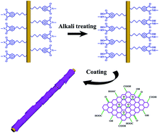
Fig. 1 illustrates the scheme to the preparation of GrPI@AT yarns. Alkali treatment leads to the hydrolysis of the imide ring, generating hydrophilic groups including carboxyl and amide groups on the surface of PI.22,23 Then these generated groups have a high reactivity with oxygen-containing groups of GO sheets, resulting in a strong interfacial adhesion.
image file: c6ra24206e-f1.tif
Fig. 1 Scheme to the preparation of graphene-bonded PI yarns with a strong interfacial adhesion (i.e., GrPI@AT yarns).

The as-received commercial PI yarns with a glassy yellow color are shown in Fig. 2a. The surface of bare and non-treated PI yarns is clean and smooth (Fig. 2b and c). The cross-sectional view of non-treated PI yarns is shown in Fig. S2a, which is compared with that of alkali-treated PI yarns (Fig. S2b). It can be learned that a modification layer occurred on the PI surface after the alkali treatment. After dipping in the GO solution and the reduction procedure, the GrPI@AT yarns were obtained and shown in Fig. 2d–f. The color has been changed from yellow to dark and is uniform in a roll of yarns (Fig. 2d). The PI yarns are fully wrapped by graphene after experiencing 12 times of dipping (Fig. 2e and f). The morphology of GrPI@AT yarns with different dipping times is shown in Fig. S3. With increasing the number of times, the graphene layer becomes thick and moreover bridges the neighboring PI fibers leading to a high conductivity.


image file: c6ra24206e-f2.tif
Fig. 2 (a) Photo of bare PI yarns. SEM images of bare PI yarns with (b) a low magnification and (c) a high magnification. (d) Photo of GrPI@AT yarns. SEM images of GrPI@AT yarns with (e) a low magnification and (f) a high magnification, which experienced 12 dipping times.

A comparison was made on morphology between GrPI@AT and GrPI@NAT yarns (Fig. 3). A good and tight interfacial bonding is observed for GrPI@AT yarns, which is ascribed to the alkali treatment (Fig. 3a). Furthermore, the graphene coating is uniform and integrated (Fig. 3b). However, the graphene coating has a loose contact with the substrate for GrPI@NAT yarns (Fig. 3c). Much worse is its cracked graphene coating (Fig. 3d), which should has a bad effect on its conductivity.


image file: c6ra24206e-f3.tif
Fig. 3 SEM images. (a) A cross-sectional view and (b) a top view of GrPI@AT yarns. (c) A cross-sectional view and (d) a top view of GrPI@NAT yarns. They all experienced 12 dipping times.

XPS analyses were conducted for bare PI yarns, GrPI@NAT and GrPI@AT yarns (Fig. 4). Here the graphene coating that formed for 1 dipping time is thin enough to enable the XPS analysis on both the surface and the interface. Table S2 shows the XPS atomic concentration where only C, N and O are observed. Compared with bare PI yarns, two composite yarns possess a relatively high concentration of C, which unveils the existence of graphene coating. The C 1s core-level XPS spectra can be decomposed by Gaussian curve fitting. In Fig. 4a for bare PI yarns, the peaks are assigned to C–C (284.8 eV), C–N (285.7 eV), C–O (286.7 eV), and C[double bond, length as m-dash]O (288.6 eV) bonds, respectively.23 In addition, the bonds can be shifted in a range of ±0.6 eV due to the interaction with other groups.24,25 Table S3 shows the peak area fractions of bonds, in which the concentration of oxygen-containing bonds for composite yarns is larger than that of the bare PI yarns. This means that the GO is not fully reduced to graphene, but it is a common issue.26


image file: c6ra24206e-f4.tif
Fig. 4 C 1s core-level XPS spectra of (a) bare PI, (b) GrPI@NAT and (c) GrPI@AT yarns.

Compared with bare PI yarns (Fig. 4a), the C–N bond of GrPI@NAT yarns (Fig. 4b) shifted from 285.7 eV to 285.2 eV, which may be ascribed to the interaction between the C–N bond of PI and the remained oxygen-containing bonds of graphene. This also happened on GrPI@AT yarns, i.e., its C–N bond shifted to 285.3 eV (Fig. 4c). For GrPI@AT yarns, new peaks show at 287.1 eV and 289.6 eV (Fig. 4c), which are attributed to HN–C[double bond, length as m-dash]O (amide) bond and O[double bond, length as m-dash]C–OH (carboxyl) bond, respectively.27 And compared with GrPI@NAT yarns, the C–O bond of GrPI@AT yarns shifted from 286.6 eV to 286.2 eV, which may be induced by the new-born amide and carboxyl bonds.

Raman spectra of PI yarn, graphene film and GrPI@AT yarn are shown in Fig. S4. Graphene film was synthesized by using the same GO solution, which was casted on a glass substrate and dried to form a GO film. Afterwards GO film was reduced to a graphene film. For PI yarn, there are strong signals at about 1513 cm−1 (C[double bond, length as m-dash]C bonding in the aromatic phenylene ring stretch), 1450 cm−1 (C–N–C axial vibration stretch) and 1780 cm−1 (C[double bond, length as m-dash]O stretch).28 Typical D (1350 cm−1) and G (1580 cm−1) bands for crystalline graphitic carbon are observed for graphene film.29 Here the high intensity ratio of D and G band (ID/IG) reveals a high degree of defects and a small average domain size of graphene.30,31 For GrPI@AT yarn, there is a slight shift to the D and G bands, which may be originated from the interfacial reaction.

FTIR spectra for bare PI, GrPI@NAT and GrPI@AT yarns are shown in Fig. S5. For bare PI yarns, the peaks at 1777, 1714 and 1380 cm−1 are ascribed to symmetric, asymmetric stretching vibrations of C[double bond, length as m-dash]O and C–N vibrations in the imide groups. The peaks at 1092, 1116 and 1168 cm−1 are attributed to deformation vibrations of (CO)2NC groups.32 The peak at 1503 cm−1 comes from benzene ring absorption. For the composite yarns, the intensity of IR absorption peaks related to the imide group is decreased indicating the existence of graphene coating. For GrPI@AT yarns, new absorption peak display at 1648 cm−1, which is assigned to stretching vibrations of C[double bond, length as m-dash]O in CONH group.33 This demonstrates that an amino compound is formed on the surface of the polyimide. Meanwhile, the peak at 1077 cm−1 (C–N stretching vibrations) indicates the chemical interaction between graphene and the surface of the yarns.34

The conductivity of GrPI@AT yarns was tested and shown in Fig. 5. The number of times of dipping has an important influence on the conductivity. A fast growth in the conductivity is witnessed when the number of times increased from 1 to 10, after that the conductivity nearly unchanged (Fig. 5a). Specifically, the conductivity of GrPI@AT yarns experiencing 12 dipping times is 1.02 × 10³ S m−1, which stands at the ceiling level of polymer fibers with conductive coatings (Fig. S1). To be mentioned, the linear mass of graphene on GrPI@AT yarns was also investigated with increasing the number of times of dipping (Fig. S6a). They are 0.0088, 0.028, 0.082, 0.108, 0.107 and 0.108 mg cm−1 for 1, 3, 8, 10, 12 and 15 times, respectively. Correspondingly, the weight contents of graphene in GrPI@AT yarns are 0.82%, 2.65%, 7.71%, 10.07%, 9.98% and 10.07%, respectively (Fig. S6b). It can be found that the mass of graphene corresponds to the conductivity. Additionally, the conductivity altered with the time of alkali treatment (Fig. S7). When increasing the time of alkali treatment, the conductivity increased to a high level and maintained. And the optimum treating time is 30 min. The conductivity of GrPI@NAT yarns was also tested and shown in Fig. S8. Its highest conductivity is 13.8 S m−1, which is two orders lower than that of the GrPI@AT yarns. This is ascribed to the loose interfacial contact and the cracked graphene coating (Fig. 3).


image file: c6ra24206e-f5.tif
Fig. 5 (a) Effect of conductivity of GrPI@AT yarn on the number of times of dipping GO solution. Stability of GrPI@AT yarn on (b) bending and twisting, (c) water wash, and (d) Scotch tape test. (e) Resistance test of GrPI@AT yarn with a length of 25 cm in various conditions. (f) GrPI@AT yarn made into a pentagram and the red circle is the start end. (g) GrPI@AT yarn serving as a flexible conductor wire to light a LED.

The stability of the conductivity of GrPI@AT yarns is shown in Fig. 5b–d. Firstly, the composite yarns underwent bending and twisting deformations, in which the bending angle is 180° and the twisting angle is 90°. The conductivity was slightly increased in both cases for 100 times (Fig. 5b). Secondly, the composite yarns were tested by water wash. They were immersed into water and swayed at a frequency of 60 Hz for 30 min, and then dried at 100 °C. Consequently, there is no exfoliation in the water (Fig. S9a) and the conductivity is stable for 10 cycles (Fig. 5c). Thirdly, the composite yarns was tested by Scotch tape. A clear surface of Scotch tape can be observed (Fig. S9b) and the conductivity kept for 10 tests (Fig. 5d). All of these verified a good interfacial adhesion between the graphene coating and the PI substrate. For a direct observation, the GrPI@AT yarns were made into various patterns and woven into fabrics (Fig. 5e and f). In all cases, the conductivity is stable and it can effectively serve as a flexible conductor wire (Fig. 5g). Moreover, the tensile properties of PI and GrPI@AT yarns were measured and the latter one possesses an enhanced tensile performance due to the good mechanical properties of graphene (Fig. S10).

The GrPI@AT yarns were further assembled into a flexible fiber-shaped supercapacitor. Two GrPI@AT yarns with a length of 3 cm were coated by gel electrolyte and then twisted to form a supercapacitor. Here, all yarns experienced 12 dipping times and the resultant graphene load is 0.107 mg cm−1 on the PI yarn. The CV spectra and voltage profiles at different current densities are shown in Fig. 6a and b, respectively. The CV curves are nearly rectangular at low scanning rates. The volumetric specific capacitance is 16.4, 12.6, 9.5 and 5.9 F cm−3 at current density of 90, 180, 360 and 720 mA cm−3, respectively (Fig. 6c). Considering the graphene weight, the gravimetric specific capacitance is 119 F g−1 corresponding to 16.4 F cm−3 based on the mass of graphene. Also the fiber-shaped supercapacitor shows an excellent long-life performance up to 3000 cycles (Fig. 6d).


image file: c6ra24206e-f6.tif
Fig. 6 Electrochemical performance of fiber-shaped supercapacitor assembled from two GrPI@AT yarns. (a) CV spectra. (b) Voltage profiles in a window from 0 to 0.8 V. (c) Rate capability. (d) Long-life performance.

Furthermore, fiber-shaped supercapacitors using GrPI@AT yarns of different lengths were studied (Fig. S11). The current density is 90 mA cm−3 for all cases. The volumetric capacitance is increased when decreasing the length of GrPI@AT yarns (Fig. S11b). For GrPI@AT yarns of 1 cm, the supercapacitor reached a high capacitance of 22.89 F cm−3. Moreover, to further enhance the electrochemical performance, polyaniline (PANI) was electrodeposited on the GrPI@AT yarns resulting in GrPI@AT–PANI yarns. The electrochemical performance is shown in Fig. S12. When the length of 3 cm and current density of 90 mA cm−3 were applied, the volumetric capacitance of the fiber-shaped supercapacitor using GrPI@AT–PANI yarns can be as high as 81.11 F cm−3, which is nearly 5 times of that without PANI. The achieved volumetric specific capacitance is higher than most of the other works based on fibers or textiles (Fig. S13).35–38

Conclusions

Graphene coating is successfully bonded on the PI yarn and the engineered strong interfacial adhesion leads to good flexibility, conductivity and stability. The conductivity reaches a high value of 1.02 × 10³ S m−1, which is at the ceiling level of polymer fibers with conductive coatings. The resultant conductive composite yarns can effectively serve as flexible conductor wire and are facilely assembled into fiber-shaped supercapacitors. Furthermore, high electrochemical performance is achieved, i.e., 22.89 F cm−3. The paper provides a general method to developing flexible conductive fibers using an interfacial modification, and a family of feasible conductive fibers that can be applicable to the present textile technology.

Acknowledgements

This work was supported by the Chinese Universities Scientific Fund (Grant No. CUSF-DH-D-2013029) and the Initial Research Funds for Young Teachers of Donghua University.

Notes and references

  1. D. Yu, K. Goh, H. Wang, L. Wei, W. Jiang, Q. Zhang, L. Dai and Y. Chen, Nat. Nanotechnol., 2014, 9, 555 CrossRef CAS PubMed.
  2. W. Weng, Q. Sun, Y. Zhang, H. Lin, J. Ren, X. Lu, M. Wang and H. Peng, Nano Lett., 2014, 14, 3432 CrossRef CAS PubMed.
  3. H. Wang, Z. Liu, J. Ding, X. Lepro, S. Fang, N. Jiang, N. Yuan, R. Wang, Q. Yin, W. Lv, Z. Liu, M. Zhang, R. Ovalle-Robles, K. Inoue, S. Yin and R. H. Baughman, Adv. Mater., 2016, 28, 4998 CrossRef CAS PubMed.
  4. Q. Huang, D. Wang and Z. Zheng, Adv. Energy Mater., 2016 DOI:10.1002/aenm.201600783.
  5. C. Hua, Y. Shang, X. Li, X. Hu, Y. Wang, X. Wang, Y. Zhang, X. Li, H. Duan and A. Cao, Nanoscale, 2016, 8, 10659 RSC.
  6. Y. Zhang, Y. Zhao, X. Cheng, W. Weng, J. Ren, X. Fang, Y. Jiang, P. Chen, Z. Zhang, Y. Wang and H. Peng, Angew. Chem., Int. Ed. Engl., 2015, 54, 11177 CrossRef CAS PubMed.
  7. G. Xin, T. Yao, H. Sun, S. Scott, D. Shao, G. Wang and J. Lian, Science, 2015, 349, 1083 CrossRef CAS PubMed.
  8. N. Behabtu, C. C. Young, D. E. Tsentalovich, O. Kleinerman, X. Wang, A. W. Ma, E. A. Bengio, R. F. ter Waarbeek, J. J. de Jong, R. E. Hoogerwerf, S. B. Fairchild, J. B. Ferguson, B. Maruyama, J. Kono, Y. Talmon, Y. Cohen, M. J. Otto and M. Pasquali, Science, 2013, 339, 182 CrossRef CAS PubMed.
  9. Z. Dong, C. Jiang, H. Cheng, Y. Zhao, G. Shi, L. Jiang and L. Qu, Adv. Mater., 2012, 24, 1856 CrossRef CAS PubMed.
  10. L. Kou and C. Gao, Nanoscale, 2013, 5, 4370 RSC.
  11. S. Chen, W. Ma, H. Xiang, Y. Cheng, S. Yang, W. Weng and M. Zhu, J. Power Sources, 2016, 319, 271 CrossRef CAS.
  12. G. Sun, L. Zheng, J. An, Y. Pan, J. Zhou, Z. Zhan, J. H. Pang, C. K. Chua, K. F. Leong and L. Li, Nanoscale, 2013, 5, 2870 RSC.
  13. W. Hou, B. Tang, L. Lu, J. Sun, J. Wang, C. Qin and L. Dai, RSC Adv., 2014, 4, 4848 RSC.
  14. S. Jiang, H. Zhang, S. Song, Y. Ma, J. Li, G. Lee, Q. Han and J. Liu, ACS Nano, 2015, 9, 10252 CrossRef CAS PubMed.
  15. P. D. Angelo and R. R. Farnood, J. Adhes. Sci. Technol., 2010, 24, 643 CrossRef CAS.
  16. X. Ji, Y. Xu, W. Zhang, L. Cui and J. Liu, Composites, Part A, 2016, 87, 29 CrossRef CAS.
  17. W. Weng, Q. Wu, Q. Sun, X. Fang, G. Guan, J. Ren, Y. Zhang and H. Peng, J. Mater. Chem. A, 2015, 3, 10942 CAS.
  18. L. E. Stephans, A. Myles and R. R. Thomas, Langmuir, 2000, 16, 4706 CrossRef CAS.
  19. S. Lee, S. S. Park and K. L. Hong, Macromol. Symp., 2007, 249–250, 586 CrossRef.
  20. Z. Zhao, C. Yan, Z. Liu, X. Fu, L. M. Peng, Y. Hu and Z. Zheng, Adv. Mater., 2016 DOI:10.1002/adma.201603679.
  21. W. Ren and H. M. Cheng, Nat. Nanotechnol., 2014, 9, 726 CrossRef CAS PubMed.
  22. S. Ikeda, H. Yanagimoto, K. Akamatsu and H. Nawafune, Adv. Funct. Mater., 2007, 17, 889 CrossRef CAS.
  23. K.-J. Min, S.-C. Park, K. H. Lee, Y. Jeong and Y.-B. Park, J. Electron. Mater., 2009, 38, 2455 CrossRef CAS.
  24. C. N. Taylor, B. Heim and J. P. Allain, J. Appl. Phys., 2011, 109, 053306 CrossRef.
  25. Y. P. Xie, G. Liu, G. Q. Lu and H. M. Cheng, Nanoscale, 2012, 4, 1267 RSC.
  26. Z. Hu, Y. Zhao, J. Liu, J. Wang, B. Zhang and X. Xiang, J. Colloid Interface Sci., 2016, 483, 26 CrossRef CAS PubMed.
  27. A. Vesel, R. Zaplotnik, G. Primc, X. Liu, K. Xu, K. C. Chen, C. Wei and M. Mozetic, Plasma Chem. Plasma Process., 2016, 36, 835 CrossRef CAS.
  28. Y. Yang, D. Yin, C. Zhong, R. Xiong, J. Shi, Z. Liu, X. Wang and Q. Lei, Polym. Eng. Sci., 2013, 53, 1536 CAS.
  29. H. J. Shin, W. M. Choi, S. M. Yoon, G. H. Han, Y. S. Woo, E. S. Kim, S. J. Chae, X. S. Li, A. Benayad, D. D. Loc, F. Gunes, Y. H. Lee and J. Y. Choi, Adv. Mater., 2011, 23, 4392 CrossRef CAS PubMed.
  30. J. Meng, D. Shi and G. Zhang, Mod. Phys. Lett. B, 2014, 28, 1430009 CrossRef.
  31. Z. Jin, J. Yao, C. Kittrell and J. M. Tour, ACS Nano, 2011, 5, 4112 CrossRef CAS PubMed.
  32. H. Ishida, S. T. Wellinghoff, E. Baer and J. L. Koenig, Macromolecules, 2002, 13, 826 CrossRef.
  33. W. L. Kang, S. P. Kowalczyk and J. M. Shaw, Langmuir, 1991, 7, 2450 CrossRef.
  34. L. Ma, G. Wang and J. Dai, J. Appl. Polym. Sci., 2016, 133, 43820 Search PubMed.
  35. W. Ma, S. Chen, S. Yang, W. Chen, W. Wei and M. Zhu, ACS Appl. Mater. Interfaces, 2016, 8, 14622 CAS.
  36. H. Jin, L. Zhou, C. L. Mak, H. Huang, W. M. Tang and H. L. W. Chan, Nano Energy, 2015, 11, 662 CrossRef CAS.
  37. J. Deng, Y. Zhang, Y. Zhao, P. Chen, X. Cheng and H. Peng, Angew. Chem., 2015, 54, 15419 CrossRef CAS PubMed.
  38. X. Xiao, T. Li, P. Yang, Y. Gao, H. Jin, W. Ni, W. Zhan, X. Zhang, Y. Cao and J. Zhong, ACS Nano, 2012, 6, 9200 CrossRef CAS PubMed.

Footnote

Electronic supplementary information (ESI) available. See DOI: 10.1039/c6ra24206e

This journal is © The Royal Society of Chemistry 2016