
Li/Ag2VO2PO4 batteries: the roles of composite electrode constituents on electrochemistry†
David C. Bocka,
Andrea M. Bruckb,
Christopher J. Pelliccionea,
Yiman Zhangb,
Kenneth J. Takeuchi*bc,
Amy C. Marschilok*bc and
Esther S. Takeuchi*abc
aBrookhaven National Laboratory, Upton, NY 11973, USA. E-mail: kenneth.takeuchi.1@stonybrook.edu; amy.marschilok@stonybrook.edu; esther.takeuchi@stonybrook.edu
bDepartment of Chemistry, Stony Brook University, Stony Brook, NY 11794, USA
cDepartment of Materials Science and Engineering, Stony Brook University, Stony Brook, NY 11794, USA
First published on 1st November 2016
Abstract
In this study, we utilize silver vanadium phosphorous oxide, Ag2VO2PO4, as a model system to systematically study the impact of the constituents of a composite electrode, including polymeric and conductive additives, on electrochemistry. Notably, although highly resistive, this bimetallic cathode can be discharged as a pure electroactive material in the absence of a conductive additive as it generates an in situ conductive matrix via a reduction displacement reaction resulting in the formation of silver metal nanoparticles. Three different electrode compositions were investigated: Ag2VO2PO4 only, Ag2VO2PO4 with binder, and Ag2VO2PO4 with binder and carbon. Constant current discharge, pulse testing and impedance spectroscopy measurements were used to characterize the electrochemical properties of the electrodes as a function of depth of discharge. In situ EDXRD was used to spatially resolve the discharge progression within the cathode by following the formation of Ag0. Ex situ XRD and EXAFS modeling were used to quantify the amount of Ag0 formed. Results indicate that the metal center reduced (V5+ or Ag+) was highly dependent on composite composition (presence of PTFE, carbon), depth of discharge (Ag0 nanoparticle formation), and spatial location within the cathode. The addition of a binder was found to increase cell polarization, and the percolation network provided by the carbon in the presence of PTFE was further increased with reduction and formation of Ag0. This study provides insight into the factors controlling the electrochemistry of resistive active materials in composite electrodes.
Introduction
The next generation of battery systems will require the full utilization of electroactive material capacity in order to improve energy density. To achieve this objective, the fast transport of both ions and electrons to all regions of the electrode is critical.1 While strategies including dimension reduction, morphology control, and synthesis of layered and tunneled structures can be used to facilitate ion diffusion, the electron access must also be considered. Low electrical conductivity can limit active material utilization, especially at high discharge or charge rates, and may be a cause of capacity fade with extended cycling. Electron access is particularly problematic in polyanion type cathode materials which provide a path toward high voltage cathode materials yet have low conductivity, including olivine LiFePO4 and LiMnPO4.2To overcome the issue of low electrical conductivity in cathode materials, battery systems utilize composite electrodes that contain conductive media, most often carbon. While widely employed, this strategy is imperfect, as inhomogeneous dispersion of the active material in the conductive additive results in incomplete electrical contact to all particles in the electrode.3,4 Another general approach is to encapsulate individual active material particles with a carbon coating.2,5 While more effective for providing electrical contact to each particle, these methods have the disadvantages of additional synthesis steps and increased production cost. An alternative strategy for approximating an ideal electrode in which each active material particle is electrically connected is to generate a conductive network in situ. Bimetallic cathode materials offer the opportunity for in situ conductive matrix formation via reduction displacement reactions that result in the formation of metal nanoparticles. These materials include Ag2V4O11,6–8 Ag4V2O6F2,9 AgFeO2,10,11 Cu2.33V4O11,12 and CuFe2O4.13
In this study, we utilize silver vanadium phosphorous oxide, Ag2VO2PO4, as a model bimetallic cathode system to study the impact of composite electrode composition on electrochemical polarization and the bimetallic discharge progression. Ag2VO2PO4 has been developed as a cathode material intended for use in batteries that power implantable cardiac defibrillators (ICDs). This application demands primary battery systems that are reliable over long periods of implantation and are able to deliver high current pulses to charge the capacitors of the device.14 With these requirements in mind, primary Li/Ag2VO2PO4 batteries are particularly promising because of their high capacity (∼270 mA h g−1), excellent rate capability with pulses >30 mA sq. cm−1,15–17 and lower cathode dissolution compared to the commercially used Li/Ag2V4O11 system.15,18–20
Ag2VO2PO4 is especially well suited for studies of discharge progression in bimetallic cathode systems. While Ag2VO2PO4 is resistive, it can be discharged as a pure material due to the change in conductivity upon initial reduction.15–17 Further, the conductivity change occurs concurrently with the in situ formation of Ag0 nanoparticles, which are detectable by diffraction based techniques, allowing discharge pathways in the material to be spatially resolved. The electrochemical discharge of Ag+ and V5+ in Ag2VO2PO4 has previously been determined to take place sequentially at low rates, with reduction of Ag+ to Ag0 occurring first but with low levels of V5+ reduction occurring concurrently.16 (Scheme 1).
 | ||
| Scheme 1 | ||
In addition to the active material and conductive additive in a composite electrode, an inert polymeric binder (PTFE, PVDF, etc.) is also typically added to provide mechanical integrity and to integrate the other components.21 The polymeric binder typically comprises only 2–5% of the total electrode mass in commercial electrodes.22 It is a critical component as it provides adhesion strength and can improve contact between active material particles with the conductive additive.23 At the same time, because of its insulating nature and electrochemical inactivity, the amount of binder in the electrode needs to be carefully considered for the specific system under study.24 While the modification of binder type and loading have been shown to affect battery performance for a range of cathode materials,22 the influence of binder on the electrochemistry of bimetallic, reduction displacement materials has not been previously reported. To provide insight, in this study Ag2VO2PO4 electrodes are investigated with three compositions: active material only, active material with 5% PTFE binder, and active material with 5% PTFE binder and 5% carbon black additive.
In order to spatially resolve the progression of discharge in the electrodes with varying composite compositions, we utilize synchrotron based energy dispersive X-ray diffraction (EDXRD). This technique provides unique insight into the state of the electrode by enabling evaluation of discharged phases as a function of spatial location. Furthermore, the white beam energy of the synchrotron light source can penetrate the steel casing of the battery, providing in situ measurements of coin type cells without the need for specially designed X-ray windows. Past studies using EDXRD have observed heterogeneous discharge with a variety of materials as a function of spatial distribution in the bulk electrode by observing the emergence of new phases and significant peak shifting.25–30 Liang et al.31 showed that EDXRD could successfully profile the state of charge of a LiMnO2-based coin cell by monitoring the emergence of the (400) peak of a compressed lattice phase of the parent material both by the peak area and the peak intensity.
EDXRD has also been used extensively to investigate the discharge characteristics of Ag2VP2O8, another member of the AgwVxPyOz family.25,32,33 The studies indicated that the spatial distribution of the Ag0 network formed is dependent on discharge rate.33 In cathodes without conductive additive, low rate initial discharge provided a more even distribution of Ag0 and thus a more effective conductive network compared to a faster discharge rate. In contrast, in cathodes containing carbon, higher initial discharge rate more effectively decreased cell impedance as a result of the formation of a greater number of smaller Ag0 crystallites. A preliminary EDXRD study of the Li/Ag2VO2PO4 cells was also performed with cathodes discharged to 2 discharge levels, indicating that reaction progress in the system could be effectively tracked.
In contrast to previous EDXRD based studies on the AgwVxPyOz family of materials, the current work focuses on investigating the component parts of a composite electrode and the how they influence electrochemical polarization and the bimetallic discharge mechanism. Several aspects of this work distinguish it from our prior publications: (1) For the first time, the role of polymeric binder on the formation of the Ag0 conductive network is considered. (2) Pulse discharge of the test cells was performed in order to quantify subtle differences in polarization among the electrode compositions. (3) The low rate discharge voltage profiles of the cells are evaluated with respect to the bimetallic discharge mechanism (reduction of Ag+ vs. V5+). (4) Ex situ extended X-ray absorption fine structure (EXAFS) at the Ag K-edge of the discharged cathodes was modelled to quantify the amount of Ag0 metal formed. In conjunction with these analyses, electrochemical impedance spectroscopy and ex situ X-ray diffraction measurements were also used to characterize Ag0 percolation network as a function of electrode composition. Results indicate a composition-dependent discharge progression in the cathodes and provide insight into the factors controlling electrochemical performance in composite cathodes containing bimetallic, reduction displacement type active materials.
Experimental methods
Materials synthesis and characterization
Silver vanadium phosphorous oxide (Ag2VO2PO4) was synthesized by a previously reported hydrothermal method.34 Briefly, the material was prepared by heating silver(I) oxide (Ag2O), vanadium(V) oxide (V2O5) and phosphoric acid (H3PO4, 85%) for 96 h at 230 °C. Differential scanning calorimetry (DSC) analysis was performed using a TA instruments Q20 with a temperature range of 40–580 °C. Powder X-ray diffraction (XRD) measurements were recorded with a Rigaku Ultima IV X-ray diffractometer using Cu Kα radiation and Bragg–Brentano focusing geometry. Samples matched the reference pattern (PDF # 97-007-3580) with no impurity phases detected.Cell assembly and testing
Three types of cathode formulations were prepared for electrochemical testing: 100% Ag2VO2PO4, 95% Ag2VO2PO4 + 5% polytetrafluoroethylene (PTFE) binder, and 90% Ag2VO2PO4 + 5% PTFE + 5% carbon black. Cathode pellets were at pressed at 4500 psi and were 13 mm in diameter with a thickness of ∼0.4 mm. Stainless steel coin cells were constructed using the cathodes, lithium metal anodes, polypropylene membrane separators, and electrolyte consisting of 1 M LiPF6 in 30![[thin space (1/6-em)]](https://www.rsc.org/images/entities/char_2009.gif) :70 ethylene carbonate:dimethyl carbonate.
:70 ethylene carbonate:dimethyl carbonate.
Coin cells from each of the three cathode formulation groups were discharged to 0.08, 0.2, and 0.5 electron equivalents at a C/500 rate (full discharge in 500 hours). An additional cell from each group was kept in the non-discharged state. Before and after discharge, Electrochemical Impedance Spectroscopy (EIS) measurements were collected using a Biologic VSP multichannel potentiostat with a 5 mV sinus amplitude and frequency range of 10 mHz to 1 MHz. Electrochemical measurements were taken at 30 °C, consistent with previous EDXRD investigations of Li/AgwVxOyPz batteries.25,32,33 While the operating temperature is 37 °C for the intended application (implanted biomedical batteries), 30 °C was chosen because it is similar to the ambient temperature of the EDXRD measurement. The small temperature difference is expected to have negligible effect on the discharge characteristics on the batteries and the spatial distribution of Ag0 formation. Equivalent circuit analysis was performed using Zview software. For undischarged cells, the charge transfer impedance was too high for the diffusional tail to be accurately quantified in the measured frequency range. When modeling impedance in these cases, the Warburg element values (ZW,R (Ω), ZW,T (Ω), ZW,P) were fixed to values of 4000, 2000, and 0.35.
In situ EDXRD
Energy dispersive X-ray diffraction (EDXRD) measurements were performed on intact, coin cells at beamline 6-BM, B at the Advanced Photon Light Source at Argonne National Laboratory. A LaB6 standard was used to calibrate the detector. The incident white beam impinged upon the sample was 20 μm in height and parallel to the sample stage, while the germanium detector used to measure the diffracted radiation was set at 2θ = 3.0°. The slit size for the detector was set such that the length of the z-direction from which diffracted X-rays were collected was ∼3.6 mm. In the x-direction, the width of the incident beam was 1.0 mm, making the dimensions of the gauge volume approximately 3.6 × 1.0 × 0.02 mm. The coin cell was placed on an automated stage such that the gauge volume was centered radially on the cell. The stage was moved upwards in the y direction through the incident beam. Thus, diffraction patterns were collected as a function of y, and a spatial profile for the cell was collected. The entire profile of the cell was measured, with measurements collected every 0.04 mm. A description of the experimental EDXRD setup including figures has been published previously.25,35 Analysis of the data was performed using MATLAB software.Ex situ analysis
Post EDXRD and electrochemical measurements, the coin cells were disassembled and the cathodes and anodes were recovered for further analyses after rinsing with dimethyl carbonate and drying. Cathodes were ground and measured by angle-resolved X-ray diffraction (XRD) using a Rigaku Miniflex XRD system (Cu Kα radiation). Peaks in the diffraction patterns were fit using PeakFit software and Pearson VII lineshape. The crystallite sizes of Ag0 component in the powders was calculated by applying the Scherrer equation36,37 to the FWHM of the Ag0(111) peak. An instrumental broadening correction was applied using a LaB6 standard. Lithium anodes were dissolved in a nitric acid solution which was then measured by inductively coupled plasma-optical emission spectroscopy (ICP-OES) using a Thermofisher ICAP 6000.Ex situ XAS
Full XAS spectra were collected at the Ag K-edge (25.51 keV) at sector 10-BM of the Advanced Photon Source at Argonne National Laboratory. Ground cathodes were sealed between Kapton tape and stored in an inert atmosphere environment until XAS measurements were collected. Each sample was measured in transmission mode with incident and transmission ion chambers filled with 100% Ar. The Si(111) double crystal monochromator was detuned to 50% for harmonic rejection. A silver metal foil was used for initial X-ray beam energy calibration and was also measured simultaneously with each sample to ensure proper energy alignment of multiple XAS scans during analysis. XAS spectra were aligned, merged and normalized using Athena.38,39 Spectra were fit using Artemis with theoretical models created by FEFF6 (ref. 40 and 41) of Ag2VO2PO4 and metallic Ag crystal structures. Fits were made using a k-range of 2–9 Å−1 with a Hanning window in k2 and k3 weighting. An R-range of 1.0–3.8 Å was used to fully encompass the |χ(R)| coordination shells of Ag atoms in Ag2VO2PO4 and Ag0 phases.Results
Materials synthesis and characterization
Synthesized Ag2VO2PO4 (SVPO) samples were characterized using X-ray powder diffraction, and the experimental XRD patterns compared well with previously reported reference data (PDF # 97-007-3580). SVPO crystallized in the monoclinic space group C2/m. As shown in Fig. S1,† the comprised of layers of distorted vanadium octahedra and PO43− tetrahedra sheets, with Ag+ ions located between the layers in a distorted octahedral coordination with oxygen. Differential scanning calorimetry was used to further assess the purity of the synthesized material (Fig. S2†). A single endothermic transition was observed, indicating the presence of a single phase material.Electrochemistry
Three types of Ag2VO2PO4 cathode formulations were electrochemically tested: 100% Ag2VO2PO4 (SVPO), 95% Ag2VO2PO4 + 5% polytetrafluoroethylene (PTFE) binder (Ag2VO2PO4 + PTFE), and 90% Ag2VO2PO4 + 5% PTFE + 5% carbon black (Ag2VO2PO4 + PTFE + C). In the ICD batteries for which the Ag2VO2PO4 cathode material is intended, the percentage of active material in the cathode composite is typically greater than 90% in order to maximize volumetric energy density.42 Thus, the selected weight ratio of active material, binder, and conductive additive is relevant for the anticipated application of the Li/Ag2VO2PO4 battery demanding high volumetric energy density. PTFE was selected instead of PVDF as the polymeric binder because it provides good adhesion to the Ag2VO2PO4 cathode material in a pressed pellet electrode form, permitting a low percentage of binder in the electrode. PTFE is commonly used as the binder in electrodes of silver vanadium oxide, the current state of the art cathode material for the ICD's, both in literature investigations7,43–47 and commercial application42,48 of the material.Li/Ag2VO2PO4 cells were galvanostatically discharged at a C/500 rate to 0.08, 0.2, and 0.5 electron equivalents, corresponding to 5.4 mA h g−1, 13.6 mA h g−1 and 34 mA h g−1, respectively (Fig. 1). These discharge levels were selected based on prior reports which indicated significant conductivity changes in Ag2VO2PO4 in the early stages of discharge.17,49,50 The C/500 rate permitted cells without conductive additive to be discharged while maintaining a loaded voltage above 2.0 V. The full discharge profile of a Li/Ag2VO2PO4 cell to theoretical capacity (4 electron equivalents, 272 mA h g−1) is presented in Fig. S3.† Despite the relatively low rate, Ag2VO2PO4 and Ag2VO2PO4 + PTFE cells display significant polarization, with voltage dropping to between 2.3–2.5 V initially and recovering as the discharge progressed. The voltage recovery behavior is consistent with the formation of Ag0 upon discharge, which enhances electronic conduction and thus allows electron access to undischarged regions of the cathode.51 It is notable that addition of the PTFE binder resulted in a lower loaded voltage (∼2.76 V for Ag2VO2PO4 + PTFE, ∼2.87 V for SVPO), suggesting that the presence of PTFE is not benign. In contrast, Ag2VO2PO4 + PTFE + C cells maintained a significantly higher loaded voltage of approximately 2.9 V throughout discharge, indicating that the addition of 5% carbon to the Ag2VO2PO4 + PTFE mixture significantly improved electron access to the Ag2VO2PO4 particles.
 | ||
| Fig. 1 Discharge profiles cells with cathodes Ag2VO2PO4-only, Ag2VO2PO4 + PTFE, and Ag2VO2PO4 + PTFE + C. | ||
Post discharge, the cells rested at open circuit potential for 24 hours followed by measurement of the electrochemical impedance spectroscopy (EIS) response. Cells of each composition in the non-discharged state were also measured. Results are presented as Nyquist plots in Fig. 2, where 2A, 2C, and 2E show the full frequency range and 2B, 2D, 2F focus on features in the high frequency region. Significant differences in the impedance spectra are observed dependent on both the discharge state of the Ag2VO2PO4 and the presence of PTFE and carbon in the composite. In cells without carbon, either with or without PTFE, the most prominent feature in the impedance spectra is a large semicircle in the nondischarged state which dramatically decreases in magnitude upon reduction. For the nondischarged cell with carbon, the initial magnitude of the middle/low frequency semicircle is lower such that it overlaps with an observable diffusional tail. Analogous to cells without carbon, the size of the semicircle markedly decreases even at low depths of discharge. EIS response was also measured after the EDXRD experiment to ensure that the X-ray exposure did not affect the properties of the cells; there were insignificant changes in the EIS response post EDXRD measurements.
 | ||
| Fig. 2 Electrochemical impedance spectroscopy results for cells with (a, b) Ag2VO2PO4-only, (c, d) Ag2VO2PO4 + PTFE, and (e, f) Ag2VO2PO4 + PTFE + C cathodes. | ||
All impedance spectra were fit to the equivalent circuit model in Fig. 3 to allow quantitative comparison of the impedance data.52,53 The selected equivalent circuit used to fit the data is a modified version of the Randles circuit54 consisting of a resistor in series with two RC elements and a Warburg element. The first resistor, R1, represents DC electrolyte resistance and ohmic resistances of the cell components and fits the intercept of the Nyquist plot in the high frequency region. R2 and CPE1 in the first parallel resistor-constant phase element component fits the high frequency semicircular features in the Nyquist plot and correspond to the ionic resistance and capacitance, respectively, of the surface film on the lithium. The third resistor (R3) and Warburg element (Wo) in parallel with constant phase element (CPE2) are used to fit the middle to low frequency spectra and approximate the charge transfer resistance, double layer capacitance and solid state diffusion of Li+ in the cathode. Assignments of these equivalent circuit elements to EIS features are consistent with previous literature.25,55–61
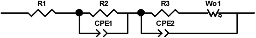 | ||
| Fig. 3 Equivalent circuit used to fit impedance spectroscopy data. | ||
Equivalent circuit fit results are tabulated in Table S4,† and the magnitude of R1, R2, and R3 are plotted as a function of depth of discharge in Fig. 4. While R1 (electrolyte, electrical contacts resistance) and R2 (anode film resistance) have low magnitude (<7 Ω for R1, <50 Ω for R2) under all conditions, the charge transfer resistance R3 is highly dependent on both the cathode composition and depth of discharge. In Ag2VO2PO4 only cathodes, upon initiation of discharge, the value of R3 decreases from 535 kΩ to ca. 155 Ω at only 0.08 electron equivalents of discharge. R3 further decreases to ca. 23 Ω and ca. 8 Ω by 0.2 and 0.5 electron equivalents, respectively. A similar trend is observed for Ag2VO2PO4 + PTFE cells, however, it is notable that at each depth of discharge the Ag2VO2PO4 + PTFE cell has a higher charge transfer resistance than its corresponding Ag2VO2PO4 only cell. At 0.5 electron equivalents, the charge transfer resistance of the Ag2VO2PO4 + PTFE cell is ca. 3× higher than the Ag2VO2PO4 only cell, indicating that the addition of PTFE to the cathode pellet hinders interparticle contact and limits the Ag0 percolation network. The addition of carbon to the cathode pellet greatly reduces the charge transfer resistance in the non-discharge state by a factor of ca. 70×. This observation was expected based on a previous study reporting that 5% carbon loading is sufficient in forming a foundational percolation network in composites with similarly sized active material particles.62
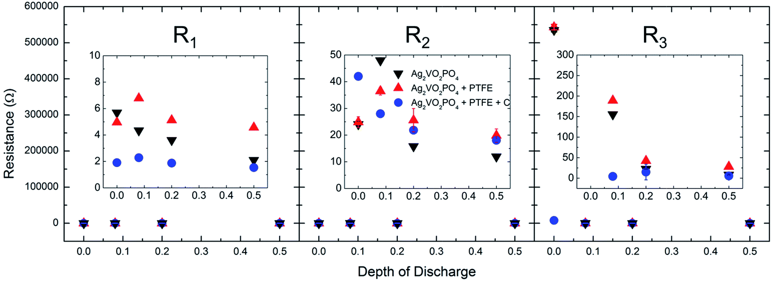 | ||
| Fig. 4 Equivalent circuit fit results as a function of depth of discharge for R1, R2 and R3. | ||
Upon reduction the charge transfer resistance in cells with carbon further reduces, suggesting that the silver reduction process still provides a conductivity benefit.
Post EDXRD measurement, the pulse discharge capability of the cells was tested to further probe the changes in conductivity observed by EIS. The pulse tests simulate intermittent therapy delivery of an implantable cardioverter defibrillator (ICD), which is the primary application for which Li/Ag2VO2PO4 batteries are intended. One cell at each condition was pulse tested with a single 10 s, 20 mA cm−2 pulse and lower voltage cutoff of 0.1 V. The voltage versus time response is shown in Fig. 5. The voltage profile of each pulse consists of 3 main parts.58,63 The initial voltage drop is due to the internal ohmic resistance of the cell and is proportional to the pulse current. The second drop occurs due to lithium intercalation in the electrode. The third component of the pulse response corresponds to the current interruption, during which the ohmic drop is regained and the cell subsequently undergoes slow relaxation to an equilibrium voltage.
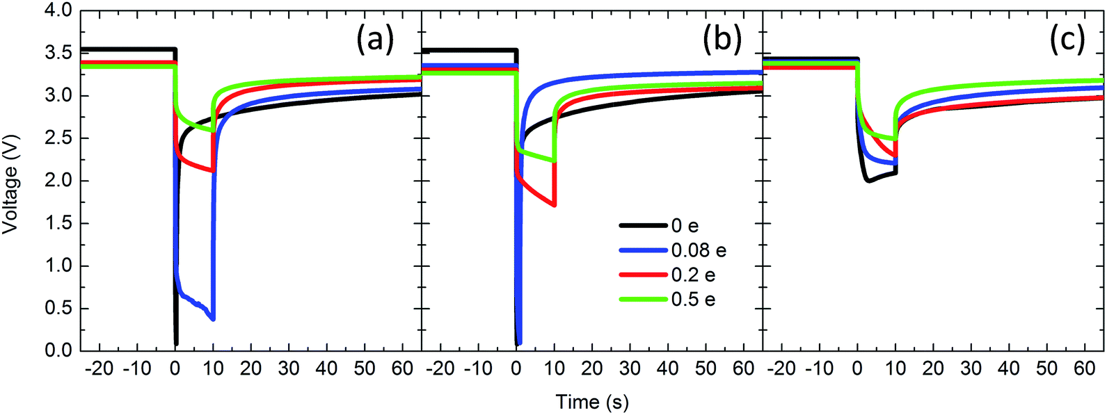 | ||
| Fig. 5 Pulse discharge tests for (a) Ag2VO2PO4 only, (b) Ag2VO2PO4 + PTFE, and (c) Ag2VO2PO4 + PTFE + C. Pulsing parameters were 10 mA cm−2 for 10 s, with a voltage cutoff of 0.1 V. | ||
Calculated total DC resistance, ohmic resistance and delivered energy of the pulse discharge tests are tabulated in Table 1. In cells without carbon (both with and without PTFE), before any discharge the ohmic resistance is too high to deliver useful power. As a result, significant polarization occurs and the voltage drops to 0.1 V (cutoff voltage). At 0.08 electron equivalents initialization of Ag0 reduction has occurred and the ohmic resistance of the Ag2VO2PO4 cell is ca. 200 Ω, such that the duration of the pulse is maintained albeit at 0.5 V. In contrast, the Ag2VO2PO4 + PTFE displays significantly higher polarization, with the voltage reaching the cutoff when the load is applied. By 0.2 e and 0.5 e DOD both Ag2VO2PO4 and Ag2VO2PO4 + PTFE cells are able to deliver useful power, consistent with the formation of a conductive Ag0 network that significantly decreases interparticle contact resistance. However, in agreement with the impedance data, the resistance of cells with PTFE is higher than those without at each depth of discharge, suggesting that the addition of PTFE impedes formation of an ideal Ag0 network where all individual particles are electrically connected.
| Composition | DOD | Total DC resistance (Ω) | Ohmic resistance (Ω) | Energy delivered (J) |
|---|---|---|---|---|
| Ag2VO2PO4 | 0 | 259 | 259 | 0.001 |
| Ag2VO2PO4 | 0.08 | 225 | 177 | 0.078 |
| Ag2VO2PO4 | 0.2 | 96 | 67 | 0.293 |
| Ag2VO2PO4 | 0.5 | 56 | 33 | 0.356 |
| Ag2VO2PO4 + PTFE | 0 | 259 | 259 | 0.001 |
| Ag2VO2PO4 + PTFE | 0.08 | 245 | 203 | 0.005 |
| Ag2VO2PO4 + PTFE | 0.2 | 120 | 90 | 0.249 |
| Ag2VO2PO4 + PTFE | 0.5 | 77 | 58 | 0.306 |
| Ag2VO2PO4 + PTFE + C | 0 | 100 | 51 | 0.279 |
| Ag2VO2PO4 + PTFE + C | 0.08 | 90 | 38 | 0.306 |
| Ag2VO2PO4 + PTFE + C | 0.2 | 77 | 29 | 0.335 |
| Ag2VO2PO4 + PTFE + C | 0.5 | 67 | 29 | 0.343 |
In contrast to the Ag2VO2PO4 only and Ag2VO2PO4 + PTFE groups, cells with the carbon additive are able to deliver a pulse voltage above 2.0 V even at the 0 DOD level, thus the carbon additive is effective in creating a primary percolation network even in the presence of the insulating PTFE binder. However, the magnitude of the ohmic drop still decreases upon discharge, from 51 Ω in the non-discharged cell to 29 Ω in the 0.5 e DOD cell. Thus, the initial percolation network in the Ag2VO2PO4 + PTFE + C electrode is not entirely sufficient for electrically connecting all particles in the cathode, and the Ag0 formation still provides significant benefit. Interestingly, at 0.5 electron DOD, the ohmic resistance of the Ag2VO2PO4 only cell is similar to that of the Ag2VO2PO4 + PTFE + C cell (33 Ω and 29 Ω for Ag2VO2PO4 only and Ag2VO2PO4 + PTFE + C cells respectively), demonstrating that the carbon additive is not necessary to achieve optimum interparticle conductivity at higher depths of discharge.
In situ energy dispersive X-ray diffraction (EDXRD)
The homogeneity of the electrode discharge can be monitored by energy dispersive X-ray diffraction (EDXRD) by spatially identifying where the Ag0 is being formed within the cathode. The diffraction pattern of each cell discharged to 0.5 e− equivalents is shown in Fig. 6 where the Ag(111) peak is clearly visible in each cell. In the Ag2VO2PO4 only cell, the Ag(111) peak appears primarily at the Li anode and steel can interfaces, indicating a heterogeneous discharge. In Ag2VO2PO4 + PTFE cathodes, a similar condition was observed where the Ag(111) peaks were observed at both interfaces rather than throughout the electrode. Adding conductive carbon caused a dramatic difference in the EDXRD results with the Ag(111) peak clearly visible at both interfaces and in the interior of the electrode. | ||
| Fig. 6 The collected EDXRD patterns from 0.35–0.55 inverse d-spacing. The arrow indicates beam position increasing away from the Li anode. The blue dashed line shows the Ag(111) peak and the red dashed line at 1/d = 0.430 is Ag2VO2PO4 (312) which is shown to distinguish it from the Ag(111) peak. The red dashed line at 1/d = 0.478 is the Ag2VO2PO4(222) and the black dashed line shows the Fe0 (110) peak which indicates the steel can. | ||
The formation of Ag0 was evaluated as a function of discharge at 0 e− equiv., 0.08 e− equiv., 0.2 e− equiv., and 0.5 e− equiv. To analyze the formation of Ag0 compared to the distribution of Ag2VO2PO4, the peak intensity of the Ag(111) diffraction plane was compared to the peak intensity of the Ag2VO2PO4(222) diffraction plane in individual cells. This method compensates for differences in attenuation from cells that are constructed with different electrode compositions. Fig. 7 shows the Ag(111)/Ag2VO2PO4(222) ratio as a function of y axis position where the zero position is the center of the Ag2VO2PO4 containing electrode. The positive values in the y axis position are towards the steel can interface and the negative values are towards the Li anode interface. Each electrode was approximately 400–450 microns thick, and additional scans were taken up to 100 microns along each interface to observe Ag0 formation at the current collector and Li anode. The position of the current collector interface differs by up to 50 microns due to slight differences in cathode thickness among the individual cells. The intensity ratio is plotted on a logarithmic scale to highlight subtle changes in the Ag0 formation within the cathodes. A ratio of Ag(111)/Ag2VO2PO4(222) equal to 1 indicates an area with very little presence of either phase, while a Ag(111)/Ag2VO2PO4(222) ratio >1 indicates a Ag0 rich region and <1 indicates a Ag2VO2PO4 rich region. The raw Ag(111) and Ag2VO2PO4(222) intensities can be found in the ESI Fig. S5–S7.†
 | ||
| Fig. 7 A comparison of the Ag0(111)/Ag2VO2PO4(222) peak intensities on a log scale from EDXRD cells as a function of spatial position where 0 is the center of the cathode. Negative spatial values are towards the Li anode and positive values are towards the steel can. The three different cell conditions (Ag2VO2PO4 only, Ag2VO2PO4 + PTFE, and Ag2VO2PO4 + PTFE + C) are shown in four different depths of discharge (0, 0.08, 0.2, and 0.5 e− equivalence). | ||
In the Ag2VO2PO4 only undischarged cell, intensity for Ag(111) is observed on the Li anode, but no additional Ag0 is observed throughout the cell or at the current collector interface. Previous studies of Ag2VO2PO4 have shown that silver ions dissolved (through ion exchange) can deposit as a silver metal layer on the lithium anode.15,19,20 This possibility was investigated further by ex situ analyses of the lithium anodes, as will be described subsequently. At higher depths of discharge, Ag2VO2PO4 cells show increased Ag0 formation primarily at the current collector interface. However, by 0.5 e−, low levels of Ag0 formation are observed to spread from the current collector interface towards the center of the cathode. In Ag2VO2PO4 + PTFE cells, a similar trend is observed where Ag0 formation is observed on the Li interface even in the non-discharged cell, and additional Ag0 formation occurs primarily at the current collector interface. By 0.5 e− the Ag0 is also observed deeper into the cathode spreading from the current collector, but at lower amounts compared to the 0.5 e− Ag2VO2PO4 only cell. The Ag0 distribution is strikingly different in the Ag2VO2PO4 + PTFE + C cells compared to the two other groups. Ag0 is visible at the Li interface in the non-discharged cell, indicating some Ag0 formation at the anode prior to discharge. However, additional Ag0 formation occurs throughout the electrode, compared to the cells without carbon where Ag0 formation occurs primarily at the cathode interface.
Ex situ analyses
Post EDXRD and electrochemical analyses, the coin cells were disassembled, and both the Ag2VO2PO4 cathodes and Li anodes were recovered for further study. The cathodes were measured by X-ray diffraction after grinding the pellet type electrodes into a fine powder where the emergence of the silver phase was apparent at higher depths of discharge, Fig. S8.† The Ag(111) peak area and Scherrer crystallite size determined from the measurements are plotted as a function of discharge level in Fig. 8. Electrodes containing carbon had higher levels of Ag0 present at each DOD, consistent with the EDXRD data. The discrepancy in the amount of silver metal formed originates at 0.08 electron equivalents, does not increase at higher levels of discharge, and thus is likely related to the conductivity of the cathode which is dependent on both depth of discharge and the presence of PTFE and/or binder. | ||
| Fig. 8 Ex situ X-ray diffraction results including Ag0(111) peak area. | ||
Ex situ X-ray absorption spectroscopy (XAS) measurements were performed on the ground pellets to further investigate the formation of Ag0 at different depths of discharge. While XRD can evaluate phase fractions of crystalline materials, XAS gives insight into the local environment of the Ag0 and Ag2VO2PO4 phases in the discharged cathodes. Unlike X-ray diffraction which relies on long range periodic structure to obtain spectra, XAS is dependent only on the local atomic structure, providing accurate evaluation of the state of Ag atoms in the electrode.64–66 X-ray absorption fine structure (EXAFS) k2 weighted-R-space spectra are shown in Fig. 9, and are overlaid with the spectra for Ag0 metal. In the undischarged state at each composition, the EXAFS spectra primarily consist of a major peak at ca. 1.6 Å originating from neighboring oxygen atoms and at ca. 3 Å correlated to Ag–P, Ag–V, as well as additional Ag–O contributions. Qualitatively it is evident that as the discharge proceeds, two new peaks form at ca. 2.25 Å and 2.75 Å which are consistent with Ag–Ag distances of fcc Ag0. For the Ag2VO2PO4 + PTFE + C composition, the peaks associated with Ag0 begin developing at lower DOD compared with the compositions which did not contain carbon. However, by 0.5 electron equivalents the magnitude of the Ag0 peaks appears more similar for all three compositions.
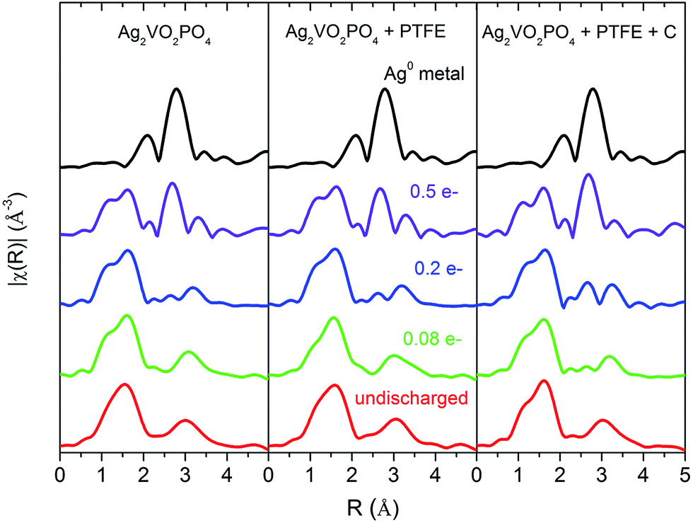 | ||
| Fig. 9 Ag K-edge k2 weighted |χ(R)| comparison of Ag2VO2PO4, Ag2VO2PO4 + PTFE, and Ag2VO2PO4 + PTFE + C cathodes at various charge/discharge levels. The spectra for Ag0 metal is included as a reference. | ||
The EXAFS spectra were fit using Artemis to quantify the relative amount of Ag0 metal and Ag2VO2PO4 in the discharged electrodes using theoretical models based on Ag2VO2PO4 and Ag0 crystal structures. For electrodes in the non-discharged state, the theoretical model of Ag2VO2PO4 consisted of 4 distinct Ag–O paths, 2 Ag–Ag paths, 1 Ag–V path, and 1 Ag–P path. Discharged electrodes were fit with an additional Ag–Ag path corresponding to the Ag–Ag interatomic distance in fcc Ag metal. Full EXAFS fitting results are tabulated in Tables S9–S12† and example EXAFS fits in k2 χ(k) and |χ(R)| are shown in Fig. S13–S16.† Results showing the relative amplitude of the Ag2VO2PO4 and Ag0 phases at each depth of discharge are shown in Fig. 10. At 0.08 electron equivalents, the relative amplitude of the Ag0 formed in Ag2VO2PO4 + PTFE + C electrodes is ca. 0.5 ± 0.2, while the amplitude in Ag2VO2PO4 and Ag2VO2PO4 + PTFE cathodes is 0. At higher electron equivalents, while the total amount of Ag0 formed increases in all electrode types, the difference in amplitude between cells with and without carbon remains between 0.4–0.7. Thus, the data are in agreement with the ex situ XRD result, and indicate that at 0.08 e− the amount of Ag0 formed in cells without carbon is significantly lower than cells with carbon, but that the amount of Ag0 formed is similar for all three groups at higher DOD. The amplitude of Ag2VO2PO4 phase consistently decreases for all electrode types by 0.5 e−, also indicating loss of Ag+ from the structure. Notably, the fitted interatomic distances for all paths within the Ag2VO2PO4 structure (Tables S9–S12†) do not shift significantly at any DOD. These data suggest that the reduction of Ag+ ions results in Ag ions exiting the lattice to form Ag0, which is consistent with previous literature showing Ag0 nanoparticle formation on the surface of Ag2VO2PO4 crystals.16
 | ||
| Fig. 10 Relative amplitude of Ag2VO2PO4 and Ag0 phases determined from EXAFS fitting. | ||
Ex situ quantitative analysis of the lithium anodes was also conducted to investigate the source of silver metal detected at the cathode/anode interface by EDXRD. Previous studies of Ag2VO2PO4 have indicated that silver ions can dissolve into the electrolyte due to an ion exchange mechanism and subsequently deposit as Ag0 metal on the lithium surface.15,19,20 Results are shown in Fig. S17.† Significant levels of Ag on the lithium surface were detected by ICP-OES for all 12 lithium anodes analyzed, suggesting Ag0 detected by EDXRD near the anode interface likely originates from silver metal deposited on the lithium subsequent to dissolution in the electrolyte. The level of vanadium on deposited on the anode was low (below 0.8 μg cm−2) for all samples, which is also consistent with previous reports that report significantly higher levels of Ag+ dissolution relative to Vn+.15,19,20
Discussion
The experimental data provide a comprehensive understanding of the components of the composite electrode and the how they impact the electrochemistry of a bimetallic phosphate active material. Results show that the discharge reaction in these cathodes is primarily limited by the kinetics of interparticle electron transfer, and as a result the addition of insulating polymeric binder and conductive carbon have a large impact on the electrode polarization both at low rate and high rates of discharge. In Ag2VO2PO4 only electrodes, significant polarization upon initial discharge at C/500 is observed, as evidenced by a drop in voltage from an OCV of ca. 3.5 V to a loaded voltage of ca. 2.3 V consistent with limited electron access among insulating Ag2VO2PO4 particles. Once a low level of Ag0 is formed via the reduction displacement mechanism in Scheme 1, electron conduction improves, allowing electron access to undischarged regions of the cathode and causing the voltage to recover to ca. 2.8 V by 0.5 electron equivalents of reduction. The Ag0 percolation network which forms dramatically decreases the charge transfer resistance of the cell, with RCT decreasing from ca. 540000 Ω in the non-discharged state to 150 Ω after 0.08 electron equivalents of discharge. The change in polarization is also observed in the pulse discharge results. The nondischarged cell is unable to deliver useful power, but after only 0.2 electron equivalents of reduction, 290 mJ of energy are delivered for a 10 s, 10 mA cm−2 pulse. Energy dispersive X-ray diffraction results show that the formation of Ag0 in Ag2VO2PO4 only cells occurs primarily at the current collector interface, and spreads further towards the center of the electrode at higher levels of discharge. Despite the spatial inhomogeneity of the reduced Ag0, the conduction network is adequate for functional operation at the pulse current tested.
The addition of PTFE polymeric binder to the active material has a notable effect on the polarization of the electrode. While the EDXRD results are similar to Ag2VO2PO4 only cells, with Ag0 formation occurring primarily at the current collector and extending into the cathode as the discharge progresses, electrochemical analysis reveals significant differences between the electrodes with and without binder. Addition of the PTFE resulted in consistently lower loaded voltages under a C/500 discharge rate when compared to the Ag2VO2PO4 only cells. Even at 0.5 electron equivalents, when ca. 12.5% of the Ag atoms in Ag2VO2PO4 are theoretically reduced, the loaded voltage is still ∼0.1 V lower in cells containing the PTFE additive. Furthermore, the charge transfer resistance, as determined via EIS, of Ag2VO2PO4 + PTFE cathodes is higher relative to Ag2VO2PO4-only cathodes at each depth of discharge. The increased polarization caused by the addition of PTFE is also manifested in the pulse discharge, with PTFE cells showing higher ohmic resistance (33 Ω and 58 Ω for Ag2VO2PO4 and Ag2VO2PO4 + PTFE cells, respectively, at 0.5 electron equivalents discharge) and lower delivered energy per pulse. These results suggest that the addition of insulating PTFE to the active material interferes with the conduction network among Ag2VO2PO4 particles.
The addition of carbon conductive additive considerably improves the electrochemical properties of the cathodes. Polarization upon initial discharge under C/500 current is minimized, with <0.1 V difference between OCV and the loaded voltage. In contrast to the other two electrode types, EDXRD shows that formation of Ag0 occurs uniformly throughout the cathode. However, the EIS and pulse discharge results suggest that the percolation network provided by the carbon in the presence of PTFE is not sufficient for optimum conductivity in the electrode. Upon reduction the charge transfer resistance of Ag2VO2PO4 + PTFE + C cells significantly decreases. Furthermore, delivered pulse power improved at each depth of discharge, indicating that formation of the Ag0 conductive network is necessary for ideal electrical connections between non-conductive active material particles in the composite.
The experiments also provide insight into the discharge mechanism occurring in the cathode pellets, and how it is impacted by the addition of PTFE and carbon. Both ex situ XRD and EXAFS indicate that at 0.08 electron equivalents DOD, the total amount of Ag0 formed in Ag2VO2PO4 + PTFE + C cells is higher than in the other 2 cells groups. However, results show that further formation of Ag0 proceeds at a similar rate for all cells regardless of conductive additive. The data suggest that whether Ag+ or V5+ metal centers reduce in Ag2VO2PO4 pellets is highly dependent on the cathode conductivity, which is determined by (1) the initial components of the composite electrode and (2) the formation of Ag0 percolation networks as the cathode is reduced. The reduction of Ag+ → Ag0 occurs at higher voltages and is preferred to V5+ → V4+ at low discharge rates based on previous reports on Ag2VO2PO4.16,49 The higher loaded voltage of Ag2VO2PO4 + PTFE + C cells and greater levels of Ag0 formation by XAS and EXAFS all indicate that in the presence of carbon, the preferred Ag+ → Ag0 reduction primarily occurs, likely due to the pre-formed percolation network afforded by the conductive additive. In comparison, in resistive Ag2VO2PO4 only and Ag2VO2PO4 + PTFE cathodes, initially only a very limited amount of active material is accessed by electrons at the current collector interface. As a result, at low levels of discharge, V5+ → V4+ reduction must occur concurrent to Ag+ → Ag0 reduction to satisfy the electron flux. Once a sufficient conductive network is formed by in situ reduction of Ag0, a greater number of Ag2VO2PO4 particles are able to be accessed by electrons and the rate of Ag+ → Ag0 reduction occurs similarly to that in cathodes containing the carbon additive. In comparing Ag2VO2PO4 only and Ag2VO2PO4 + PTFE cathodes, EIS and pulse discharge data indicate that the addition of PTFE without carbon is detrimental to the conductivity of the cathode. While XRD and EXAFS results do not detect significant differences in the amount of Ag0 formed, the addition of PTFE does result in consistently lower loaded voltages. Thus, it is likely that cathodes with PTFE may have a higher level of vanadium reduction rather than silver ion reduction relative to the pure active material.
The conductivity-dependent discharge progression is summarized in Fig. 11. Upon initial discharge in insulating Ag2VO2PO4 cathodes, the preferred Ag+ → Ag0 reduction occurs primarily at the current collector interface, with V5+ → V4+ occurring concurrently due to lack electron access. In Ag2VO2PO4 + PTFE cathodes, the insulating binder blocks some Ag2VO2PO4–Ag0–Ag2VO2PO4 connections, further reducing interparticle conductivity. In cathodes with the carbon additive, Ag+ → Ag0 reduction is the primary discharge mechanism and occurs uniformly throughout the electrode. As the discharge progresses, in cathodes w/out carbon, a greater number of Ag2VO2PO4 particles are accessible to electrons due to the conductive silver network, and Ag+ reduction occurs at rate similar to that in cells with carbon. The reduced Ag0 is concentrated close to the current collector but spreads into the cathode as the discharge progresses. The presence of PTFE blocks some conductive pathways created by the Ag0 network, resulting in a higher amount of vanadium reduction, lower loaded voltage, and poorer pulse performance. In Ag2VO2PO4 + PTFE + C cathodes, the discharge continues to progress uniformly with Ag reduction being the primary mechanism, with some amount of V reduction likely as well. The carbon alone does not yet provide ideal interparticle contact between Ag2VO2PO4 particles, as indicated by the improved pulse capability as the material is reduced and Ag0 is formed.
 | ||
| Fig. 11 Schematic diagram of the discharge progression in Ag2VO2PO4, Ag2VO2PO4 + PTFE, and Ag2VO2PO4 + PTFE + C. The current collector is represented by the grey bar on the left of each figure. | ||
Conclusions
In batteries with composite cathodes containing the insulating bimetallic active material Ag2VO2PO4, consideration of both insulating polymeric binder and conductive carbon additive incorporation is critical for understanding electrochemical polarization in the system. Results from a combination of measurement techniques including EIS, pulse testing, in situ EDXRD, ex situ XRD, and EXAFS modeling show that electrical conductivity can be the limiting factor for discharging the material, thus, the reduction mechanism (extent of V5+ → V4+ vs. Ag+ → Ag0 reduction) is highly dependent on composite composition (presence of PTFE, carbon), depth of discharge (Ag0 nanoparticle formation), and spatial location within the cathode. The findings suggest that the incorporation of PTFE without carbon limits the effectiveness of the Ag0 conduction network formed on reduction. Furthermore, carbon in the presence of PTFE decreases impedance significantly. However, the impedance is further reduced on initiation of reduction concomitant with the formation of Ag0 nanoparticles. The implications of these results can be extended to consider electrode constructs to reduce the impedance of other resistive electroactive materials which are utilized as composites.Acknowledgements
This work was supported as part of the Center for Mesoscale Transport Properties, an Energy Frontier Research Center supported by the U.S. Department of Energy, Office of Science, Basic Energy Sciences, under award #DE-SC0012673 for financial support. This research used resources of the Advanced Photon Source beamlines 6-BM, B and 10-BM, a U.S. Department of Energy (DOE) Office of Science User Facility operated for the DOE Office of Science by Argonne National Laboratory under Contract No. DE-AC02-06CH113. Use of APS Beamline 6-BM is partially supported by the National Synchrotron Light Source II, Brookhaven National Laboratory, under DOE Contract No. DE-SC0012704. A. M. B. acknowledges the support of the National Science Foundation Graduate Research Fellowship under grant No. 1109408. Any opinions, findings, and conclusions or recommendations expressed in this material are those of the authors and do not necessarily reflect the views of the National Science Foundation.Notes and references
- N. J. Dudney and J. Li, Science, 2015, 347, 131–132 CrossRef CAS PubMed.
- N. Nitta, F. Wu, J. T. Lee and G. Yushin, Mater. Today, 2015, 18, 252–264 CrossRef CAS.
- R. Cornut, D. Lepage and S. B. Schougaard, J. Electrochem. Soc., 2012, 159, A822–A827 CrossRef CAS.
- J. L. Li, B. L. Armstrong, C. Daniel, J. Kiggans and D. L. Wood, J. Colloid Interface Sci., 2013, 405, 118–124 CrossRef CAS PubMed.
- J. J. Wang and X. L. Sun, Energy Environ. Sci., 2012, 5, 5163–5185 CAS.
- E. S. Takeuchi and W. C. Thiebolt III, J. Electrochem. Soc., 1988, 135, 2691–2694 CrossRef CAS.
- K. J. Takeuchi, R. A. Leising, M. J. Palazzo, A. C. Marschilok and E. S. Takeuchi, J. Power Sources, 2003, 119–121, 973–978 CrossRef CAS.
- K. J. Takeuchi, A. C. Marschilok, S. M. Davis, R. A. Leising and E. S. Takeuchi, Coord. Chem. Rev., 2001, 219–221, 283–310 CrossRef CAS.
- F. Sauvage, V. Bodenez, H. Vezin, T. A. Albrecht, J.-M. Tarascon and K. R. Poeppelmeier, Inorg. Chem., 2008, 47, 8464–8472 CrossRef CAS PubMed.
- J. L. Durham, K. Kirshenbaum, E. S. Takeuchi, A. C. Marschilok and K. J. Takeuchi, Chem. Commun., 2015, 51, 5120–5123 RSC.
- K. E. Farley, A. C. Marschilok, E. S. Takeuchi and K. J. Takeuchia, Electrochem. Solid-State Lett., 2012, 15, A23–A27 CrossRef CAS.
- M. Morcrette, P. Rozier, L. Dupont, E. Mugnier, L. Sannier, J. Galy and J. M. Tarascon, Nat. Mater., 2003, 2, 755–761 CrossRef CAS PubMed.
- C. A. Cama, C. J. Pelliccione, A. B. Brady, J. Li, E. A. Stach, J. Wang, J. Wang, E. S. Takeuchi, K. J. Takeuchi and A. C. Marschilok, Phys. Chem. Chem. Phys., 2016, 18, 16930–16940 RSC.
- D. C. Bock, A. C. Marschilok, K. J. Takeuchi and E. S. Takeuchi, Electrochim. Acta, 2012, 84, 155–164 CrossRef CAS PubMed.
- D. C. Bock, R. V. Tappero, K. J. Takeuchi, A. C. Marschilok and E. S. Takeuchi, ACS Appl. Mater. Interfaces, 2015, 7, 5429–5437 CAS.
- E. S. Takeuchi, A. C. Marschilok, K. Tanzil, E. S. Kozarsky, S. Zhu and K. J. Takeuchi, Chem. Mater., 2009, 21, 4934–4939 CrossRef CAS PubMed.
- A. C. Marschilok, K. J. Takeuchi and E. S. Takeuchi, Electrochem. Solid-State Lett., 2008, 12, A5–A9 CrossRef.
- D. C. Bock, A. C. Marschilok, K. J. Takeuchi and E. S. Takeuchi, J. Power Sources, 2013, 231, 219–235 CrossRef CAS PubMed.
- D. C. Bock, K. J. Takeuchi, A. C. Marschilok and E. S. Takeuchi, Dalton Trans., 2013, 42, 13981–13989 RSC.
- D. C. Bock, K. J. Takeuchi, A. C. Marschilok and E. S. Takeuchi, Phys. Chem. Chem. Phys., 2015, 17, 2034–2042 RSC.
- M. Zhu, J. Park and A. M. Sastry, J. Electrochem. Soc., 2011, 158, A1155–A1159 CrossRef CAS.
- S. L. Chou, Y. D. Pan, J. Z. Wang, H. K. Liu and S. X. Dou, Phys. Chem. Chem. Phys., 2014, 16, 20347–20359 RSC.
- G. Liu, H. Zheng, S. Kim, Y. Deng, A. M. Minor, X. Song and V. S. Battaglia, J. Electrochem. Soc., 2008, 155, A887–A892 CrossRef CAS.
- H. H. Zheng, R. Z. Yang, G. Liu, X. Y. Song and V. S. Battaglia, J. Phys. Chem. C, 2012, 116, 4875–4882 CAS.
- K. C. Kirshenbaum, D. C. Bock, Z. Zhong, A. C. Marschilok, K. J. Takeuchi and E. S. Takeuchi, Phys. Chem. Chem. Phys., 2014, 16, 9138–9147 RSC.
- J. W. Gallaway, B. J. Hertzberg, Z. Zhong, M. Croft, D. E. Turney, G. G. Yadav, D. A. Steingart, C. K. Erdonmez and S. Banerjee, J. Power Sources, 2016, 321, 135–142 CrossRef CAS.
- G. Liang, M. C. Croft and Z. Zhong, ECS Trans., 2013, 50, 293–304 CrossRef.
- H. Murayama, K. Kitada, K. Fukuda, A. Mitsui, K. Ohara, H. Arai, Y. Uchimoto, Z. Ogumi and E. Matsubara, J. Phys. Chem. C, 2014, 118, 20750–20755 CAS.
- W. A. Paxton, Z. Zhong and T. Tsakalakos, J. Power Sources, 2015, 275, 429–434 CrossRef CAS.
- F. C. Strobridge, B. Orvananos, M. Croft, H.-C. Yu, R. Robert, H. Liu, Z. Zhong, T. Connolley, M. Drakopoulos, K. Thornton and C. P. Grey, Chem. Mater., 2015, 27, 2374–2386 CrossRef CAS.
- G. Liang, M. C. Croft and Z. Zhong, J. Electrochem. Soc., 2013, 160, A1299–A1303 CrossRef CAS.
- K. Kirshenbaum, D. Bock, Z. Zhong, A. C. Marschilok, K. J. Takeuchi and E. S. Takeuchi, J. Mater. Chem. A, 2015, 3, 18027–18035 CAS.
- K. Kirshenbaum, D. C. Bock, C.-Y. Lee, Z. Zhong, K. J. Takeuchi, A. C. Marschilok and E. S. Takeuchi, Science, 2015, 347, 149–154 CrossRef CAS PubMed.
- H. Y. Kang, S. L. Wang, P. P. Tsai and K. H. Lii, J. Chem. Soc., Dalton Trans., 1993, 1525–1528 RSC.
- E. S. Takeuchi, A. C. Marschilok, K. J. Takeuchi, A. Ignatov, Z. Zhong and M. Croft, Energy Environ. Sci., 2013, 6, 1465–1470 CAS.
- P. Scherrer, Nachrichten von der Gesellschaft der Wissenschaften zu Göttingen, 1918, 96–100 CAS.
- A. L. Patterson, Phys. Rev., 1939, 56, 978–982 CrossRef CAS.
- M. Newville, J. Synchrotron Radiat., 2001, 8, 322–324 CrossRef CAS PubMed.
- B. Ravel and M. Newville, J. Synchrotron Radiat., 2005, 12, 537–541 CrossRef CAS PubMed.
- J. Mustre de Leon, J. J. Rehr, S. I. Zabinsky and R. C. Albers, Phys. Rev. B: Condens. Matter Mater. Phys., 1991, 44, 4146–4156 CrossRef CAS.
- J. J. Rehr, J. Mustre de Leon, S. I. Zabinsky and R. C. Albers, J. Am. Chem. Soc., 1991, 113, 5135–5140 CrossRef CAS.
- D. Linden and T. B. Reddy, in Handbook of Batteries, ed. D. Linden and T. B. Reddy, McGraw-Hill, 2002, vol. 3 Search PubMed.
- Y. K. Anguchamy, J.-W. Lee and B. N. Popov, J. Power Sources, 2008, 184, 297–302 CrossRef CAS.
- X. Cao, L. Xie, H. Zhan and Y. Zhou, Inorg. Mater., 2008, 44, 886–889 CrossRef CAS.
- A. Crespi, C. Schmidt, J. Norton, K. Chen and P. Skarstad, J. Electrochem. Soc., 2001, 148, A30–A37 CrossRef CAS.
- R. A. Leising and E. S. Takeuchi, Chem. Mater., 1994, 6, 489–495 CrossRef CAS.
- S. Zhang, W. Li, C. Li and J. Chen, J. Phys. Chem. B, 2006, 110, 24855–24863 CrossRef CAS PubMed.
- A. M. Crespi, S. K. Somdahl, C. L. Schmidt and P. M. Skarstad, J. Power Sources, 2001, 96, 33–38 CrossRef CAS.
- A. C. Marschilok, E. S. Kozarsky, K. Tanzil, S. Zhu, K. J. Takeuchi and E. S. Takeuchi, J. Power Sources, 2010, 195, 6839–6846 CrossRef CAS PubMed.
- A. C. Marschilok, Y. J. Kim, K. J. Takeuchi and E. S. Takeuchi, J. Electrochem. Soc., 2012, 159, A1690–A1695 CrossRef CAS.
- K. C. Kirshenbaum, D. C. Bock, A. B. Brady, A. C. Marschilok, K. J. Takeuchi and E. S. Takeuchi, Phys. Chem. Chem. Phys., 2015, 17, 11204–11210 RSC.
- D. D. Macdonald, Electrochim. Acta, 2006, 51, 1376–1388 CrossRef CAS.
- J. R. Macdonald, J. Electroanal. Chem., 1987, 223, 25–50 CrossRef CAS.
- J. E. B. Randles, Discuss. Faraday Soc., 1947, 1, 11–19 RSC.
- E. Prada, D. Di Domenico, Y. Creff, J. Bernard, V. Sauvant-Moynot and F. Huet, J. Electrochem. Soc., 2013, 160, A616–A628 CrossRef CAS.
- H. Nakahara, S.-Y. Yoon, T. Piao, F. Mansfeld and S. Nutt, J. Power Sources, 2006, 158, 591–599 CrossRef CAS.
- S. Yang, J. Huo, H. Song and X. Chen, Electrochim. Acta, 2008, 53, 2238–2244 CrossRef CAS.
- R. P. Ramasamy, C. Feger, T. Strange and B. N. Popov, J. Appl. Electrochem., 2006, 36, 487–497 CrossRef CAS.
- C. J. Zhang, X. He, Q. S. Kong, H. Li, H. Hu, H. B. Wang, L. Gu, L. Wang, G. L. Cui and L. Q. Chen, CrystEngComm, 2012, 14, 4344–4349 RSC.
- X. Liu, M. Wu, M. Li, X. Pan, J. Chen and X. Bao, J. Mater. Chem. A, 2013, 1, 9527–9535 CAS.
- M. D. Levi and D. Aurbach, J. Power Sources, 2005, 146, 727–731 CrossRef CAS.
- M. E. Spahr, D. Goers, A. Leone, S. Stallone and E. Grivei, J. Power Sources, 2011, 196, 3404–3413 CrossRef CAS.
- Y. K. Anguchamy, J.-W. Lee and B. N. Popov, J. Power Sources, 2008, 184, 297–302 CrossRef CAS.
- C. J. Pelliccione, E. V. Timofeeva and C. U. Segre, Chem. Mater., 2015, 27, 574–580 CrossRef CAS.
- C. J. Pelliccione, Y. R. Li, A. C. Marschilok, K. J. Takeuchi and E. S. Takeuchi, Phys. Chem. Chem. Phys., 2016, 18, 2959–2967 RSC.
- C. J. Pelliccione, E. V. Timofeeva and C. U. Segre, J. Phys. Chem. C, 2016, 120, 5331–5339 CAS.
Footnote |
| † Electronic supplementary information (ESI) available: Differential scanning calorimetry of Ag2VO2PO4, EIS fitting results, EDXRD peak intensities, ex situ XRD, full EXAFS fitting results, quantitative analysis of Li anodes. See DOI: 10.1039/c6ra24024k |
| This journal is © The Royal Society of Chemistry 2016 |