Body armour materials: from steel to contemporary biomimetic systems
Ramdayal
Yadav
a,
Minoo
Naebe
*a,
Xungai
Wang
a and
Balasubramanian
Kandasubramanian
*b
aDeakin University, Institute for Frontier Materials (IFM), Geelong, Australia. E-mail: minoo.naebe@deakin.edu.au
bDepartment of Materials Engineering, Defence Institute of Advanced Technology, Ministry of Defence, Girinagar, Pune-411025, India. E-mail: meetkbs@gmail.com
First published on 30th November 2016
Abstract
The history of armour is as old as the evolution of mankind; indeed, it is an intrinsic instinct of humanity to protect and shield ourselves from danger, such as from various critical environments and from other humans, especially in a battlefield setting. The development of high-speed projectiles and explosive materials changed the dynamics of the battlefield and led to an evolution in advanced ballistic personal protection systems, with requirements for the new systems to be damage resistant, flexible and lightweight, and with an efficient energy absorbing capacity. Steel was the preferred material in the battlefield for our ancestors, but in modern days, especially in the last two decades, new design strategies and materials, including fibres, composites, laminates, ceramics and bioinspired materials, have been extensively exploited to accomplish the requirements of modern military operations, and to provide protection appropriate for modern technology-driven war tactics and for protection against current terror threats. The present review covers the general strategies and materials used in armour systems, from felt to metals and composites, which themselves have been further extended, particularly to now include bioinspired materials and utilizing biomimetic conditions. Detailed discussions regarding the various armour materials and any issues in their performance against modern ammunition systems are outlined.
1 Introduction
Human consciousness has been engrained since the beginning of the civilization to defend, protect, save, shield and guard ourselves from harm. The history of protective materials and their role is vast and hence a complete chronological account of all the significant changes in the advancement of these materials is impossible. However, it is well-established that proper protective tactics have saved mankind from various threats throughout history, including threats from the environment, enemies and animals. For centuries, humans have sought to expand their territories in the hunt for food, life, resources, riches or just new territory. Alongside this drive for expansion, the threat of warfare between societies evolved, and just as new weapons emerged, so did the need to utilize personal protection systems, which since early days were called “armour”. Armour can be defined as a system covering a body or object with the aim being to provide maximum possible resistance to penetration by all types of projectiles as well as from fragmentation resulting from the detonation of high explosives shells, grenades, mines, high-velocity jets kinetic energy penetration, etc. In addition, armour must resist cracking, spalling and fracture upon multiple impacts, while at the same time maintaining structural integrity if it is used as part of a structure.1The history of armour is not clear from early man, since we do not have actual prototypes from archaeological findings, but from the records we do have, we can say that historically the Assyrians (1100–600 B.C.) had the most advanced amour in the ancient world in terms of armour materials and systems, which included felt, wool, leather, wood, iron and bronze. The Persians (500 B.C.) and the Greeks were possibly the next key groups that utilized armour for their protection. The Greeks acquired considerable expertise and sophistication in working with large bronze plates, while the Romans who followed the ancient Greeks expanded their expertise of fabricating flexible cuirasses made from iron plates mounted on a leather harness. The Romans extensively exploited iron for protecting themselves against contemporary weapons and arms. Globally, the proficiency in working with steel reached its peak during the Medieval Period, where the knights were able to wear complete suits of armour but with enhanced mobility and freedom compared to early suits of armour. Simo Dunstan reported that quilted coats of ring mail and many other combinations of all these materials were the most common materials in ancient and medieval times.2–18
Since the main sources of information on ancient armour are mainly based on sculptures, paintings and coins from the time, it would be challenging to lay out an accurate table for the chronical development of all the materials and designs relating to the development of armour over time. However, notwithstanding this challenge the development of armour in terms of some known protective materials and designs utilized in some major civilizations are illustrated in Table 1 based on the literary work of Roy C. Liable and J. Paul Hazzel.2–19
| Kingdom | Armour materials and designs |
|---|---|
| Egyptians | Linen, bronze, steel, wool, wood |
| Sumerians | Linen, bronze, steel, wool, wood |
| Akkadians | Metal helmet, boiled leather breast plate |
| Assyrians | Felt, wool, leather, wood, iron, bronze |
| Persians | Leather, iron, bronze |
| Greeks | Metallic armour, leather armour |
| Romans | Iron, laminated cuirass, scale armour, plate armour |
| Charlemagne's era | Coat of scale armour (Jazerant) |
| Norman | Iron, bronze, leather, horn, quilted armour |
| Saxons | Byrnie |
| Crusades | Borgne, interlaced metal rings or chains |
| 1400 A.D. | Armour plates, breastplates, gauntlets for the hands, narrow waited cuirass, greaves and sollerets |
| 16th century | Fluted or channelled armour with manganese alloy |
| 17th century | The thickness of the metal armour was increased to protect from newly developed fire arms |
| English civil war (1642–1648) | Metal breastplate and helmet |
| Japanese–Russian war (1905) | Silk vests as armour |
| World War I | Metal helmets, heavy metal breastplate, armoured waistcoat |
| World War II | Steel plates, doron plates, comprising laminates of fibreglass and polyester and nylon |
| 1960s and later | Ceramic armour, aluminium oxide first introduced into armour, fibreglass laminates, boron carbide, polyaramids |
Despite all the craftsmanship reported for the development of armour materials and new designs to combat contemporary arms and weapons, the advent of handheld firearms in the seventeenth century changed the dynamics of the battlefield. It has been reported that machine guns, rifle fire and shrapnel produced appalling casualties during World War I. The advent of trench warfare further alarmingly enhanced the incidence of head injuries due to soldiers being hit by shell fragments.18 Though, various strategies have been employed based on prior experience and advancements in arms and ammunition for developing armour materials, there were no systematic studies reported on the protection of individual soldiers. Coates and Bayer in their study considered discrete elements, including ballistics characteristics and the relative anatomy of the body with regard to various potential wounds, for the effective threat analysis of potential injuries that could occur during fighting in World War II and the Korean War.20 Their study revealed that, on average, injuries of the head and neck accounted for 12%, thorax 16%, abdomen 11%, upper limbs 22% and lower limbs 39% for full-standing soldiers. T. W. Baskin illustrated the anatomical distribution of low-velocity incapacitating wounds resulting from modern fragmentation weapons, as illustrated in Table 2.21 Hofmeister et al. reported how, on average, survival rates for battlefield injuries have dramatically increased since World War I due to the progress in modern body armour systems and advanced war-time treatment facilities (Table 3).22
| Conflict | Head & neck injuries (%) | Thorax (%) | Abdomen (%) | Limbs (%) |
|---|---|---|---|---|
| World War I | 17 | 4 | 2 | 70 |
| World War II | 4 | 8 | 4 | 75 |
| Korean War | 17 | 7 | 7 | 67 |
| Vietnam War | 14 | 7 | 5 | 74 |
| Afghanistan conflict | 16 | 12 | 11 | 61 |
| War | % surviving battlefield injuries |
|---|---|
| World War I | 21% (approx.) |
| World War II | 69.7% |
| Vietnam War | 76.4% |
| Iraq War | 88.2% |
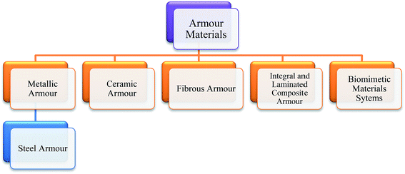
In spite of all these studies, in development of materials and design, the primary function of armour remains same: to impede weapon and projectile penetration into the human body and to diffuse the impact energy. However, the prerequisites of the materials have enormously changed in the last two decades and now include greater flexibility (wearability and mobility of the wearer), lightweight, damage resistance and multi-hit capability, together with an efficient energy absorbing capacity with minimum physiological stress.23 In this review, we aimed to highlight the factors governing the evolution of advanced technology and materials for body armour applications, and at the same time to elaborate on the reasons behind the obsolescence of some forms of ancient armour. Although, various literature reports on personal protection systems are available in the form of defence reports, case studies and book chapters, extensive illustrations of various armour materials (Fig. 1), their penetration–protection mechanisms and their historical aspects are less reported in the research articles. Therefore, the present review will discuss in detail the standards and specifications of armour, the armour materials themselves and the issues regarding their performance against modern ammunition systems.
1.1 Standards and specifications
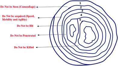
Graham Cooper and Philip Gotts define protective armour in terms of any material that provides protection from energy, where that energy is principally in the form of impact by a penetrating, non-penetrating or blast-wave projectile, blows or missiles.24 The primary function of armour includes absorbing and redistributing energy generated due to the projectiles or explosives and extending the time before it approaches the actual body. In addition, armour should be flexible, lightweight, damage resistant and have a multi-hit capability with minimum physiological stress. In recent years, body armour has been designed with various layers to accomplish the requirements of modern ammunition warfare, whereby these layers of protection can be thought of in terms of the concept of “onion survivability”, which is illustrated in Fig. 2.19In order to provide standard methods to assess the efficacy and proficiency of an armour material, various standards and specifications are practiced around the world, and some of these are described in the section below.25
(a) Body armour.
(b) Armoured seats for aircraft and ground vehicles.
(c) Crew station armour for military aircraft.
(d) Internal and external armour for aircraft.
(e) Transparent armour, such as windows, windshields and vision blocks for aircraft and ground vehicles.
(f) Bulkhead armour for shipboard use.
(g) Structural or integral armour for use on ship exteriors.
(h) Armour for military tactical shelters (AFWAL-TR-82-4163).
(i) Visors for eye and face protection.
(j) Armour for potential space applications.
(k) Armour for light and heavy combat vehicles and structures.
General requirement.
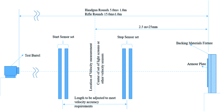
Projectile. The specified projectile should be used in the testing procedure by utilizing a millimetre unit to identify the calibre of bullet.
Weapons. The weapon(s) used in the ballistic test firing should be capable of firing the appropriate projectile at the specified V50BL(P) velocity range within yaw limitations. Millimetres should be used to identify the calibre of weapons unless otherwise specified.
Velocity measuring equipment.
Chronograph. An electronic counter-type chronograph measuring to at least the nearest microsecond (10–6 s) should be used.
Detectors. The utilized detector should contain either high-velocity lumiline screens or electrical contact screens that either open or close an electrical circuit by passage of the projectile. Contact screens may consist of metallic foils separated by a thin insulating layer, or may consist of a circuit printed on paper with the circuit spacing such that the projectile passing through the screen will “break” the circuit. The used chronograph or electronic timers should be calibrated and certified for accuracy. If accuracy is not certified, two pairs of velocity screens and two chronograph counters should be used. This system enables the computation of an average projectile velocity between each pair of screens. The difference between the two instrumentation velocities should be less than or equal to 10 ft s−1 (3 m s−1); thus, giving greater accuracy of the actual average velocity.
Radar. A Doppler radar should be used occasionally to check the lumiline screens.
Propellants. Any propellants that are standard or suitable for the weapons can be utilized and the projectile velocity propellant charge curve for the weapon should be determined before initiating the test procedure, since the curve renders the basis for selecting a powder charge to achieve the desired velocity. It is recommended that the propellant storage and weighing area be maintained at 19–24 °C (65–75 °F) and 50% + 5% relative humidity.
Test sample mount. The armour test sample should be secured on the test target mounted with the impact side perpendicular to the line-of-flight of the projectile. The frame supports and clamps or mounting fixtures must be capable of retaining the sample and withstanding the shock resulting from the ballistic impact by the test projectiles. The test sample mounts should be capable of adjustment for moving the sample in the vertical or horizontal directions so that the point of impact can be located anywhere on the sample, and so that the zero-degree obliquity impacts can be achieved anywhere on the sample. The test sample mounts should be able to rotate on the vertical or horizontal axis so that various obliquity attack angles can be achieved. The test samples should be mounted with a rigidity equal to or greater than the actual installation of the part.
Test samples. The sampling plan for the ballistic acceptance tests should be specified.
The rejection or acceptance of the selected armour samples depends on the minimum V50BL(P) ballistic requirements specified. If any sample fails to reconcile with the minimum specified V50BL (P) ballistic limit, the entire lot that the sample represents will be rejected.
| Armour type | Test rounds | Test bullets | Bullet mass | Conditioned armour test velocity | New armour test velocity | Hits per panel at 0° | Max BFS depth | Hits per panel at 30° and 45° | Shots per panel | Panel size | Panel condition | Panel required | Shots required | Total shots required |
|---|---|---|---|---|---|---|---|---|---|---|---|---|---|---|
| IIA | 1 | 9 mm FMJ RN | 8.0 g | 355 m s−1 | 373 m s−1 | 4 | 44 | 2 | 6 | Large | New | 4 | 24 | 144 |
| Conditioned | 2 | 12 | ||||||||||||
| Small | New | 4 | 24 | |||||||||||
| Conditioned | 2 | 12 | ||||||||||||
| 2 | 0.40 S & W FMJ RN | 11.7 g | 325 m s−1 | 352 m s−1 | 4 | 44 | 2 | 6 | Large | New | 4 | 24 | ||
| Conditioned | 2 | 12 | ||||||||||||
| Small | New | 4 | 24 | |||||||||||
| Conditioned | 2 | 12 | ||||||||||||
| II | 1 | 9 mm FMJ RN | 8.0 g | 379 m s−1 | 398 m s−1 | 4 | 44 | 2 | 6 | Large | New | 4 | 24 | 144 |
| Conditioned | 2 | 12 | ||||||||||||
| Small | New | 4 | 24 | |||||||||||
| Conditioned | 2 | 12 | ||||||||||||
| 2 | 0.357 Magnum JSP | 10.0 g | 408 m s−1 | 436 m s−1 | 4 | 44 | 2 | 6 | Large | New | 4 | 24 | ||
| Conditioned | 2 | 12 | ||||||||||||
| Small | New | 4 | 24 | |||||||||||
| Conditioned | 2 | 12 | ||||||||||||
| IIIA | 1 | 0.357 SIG FMJ FN | 8.1 g | 430 m s−1 | 448 m s−1 | 4 | 44 | 2 | 6 | Large | New | 4 | 24 | 144 |
| Conditioned | 2 | 12 | ||||||||||||
| Small | New | 4 | 24 | |||||||||||
| Conditioned | 2 | 12 | ||||||||||||
| 2 | 0.44 Magnum SJHP | 15.6 g | 408 m s−1 | 436 m s−1 | 4 | 44 | 2 | 6 | Large | New | 4 | 24 | ||
| Conditioned | 2 | 12 | ||||||||||||
| Small | New | 4 | 24 | |||||||||||
| Conditioned | 2 | 12 | ||||||||||||
| III | 1 | 7.62 mm NATO FMJ | 9.6 g | 847 m s−1 | — | 6 | 44 | 0 | 6 | All | Conditioned | 4 | 24 | 24 |
| IV | 1 | 0.30 Calibre M2 AP | 10.8 g | 878 m s−1 | — | 1 to 6 | 44 | 0 | 1 to 6 | All | Conditioned | 4 to 24 | 24 | 24 |
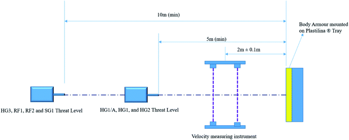
HG1/A. Lightweight-flexible soft armour intended for use by unarmed officers in very-low-risk patrolling situations. Suitable for both overt and covert use.
HG1. General duty soft armour for low-risk situations. May be overt or covert.
HG2. Special duty soft armour intended for use in firearms operations. Can be used in conjunction with RF1 and SG1 plates. Usually overt.
HG3. Heavy duty armour intended for use in firearms operations. Can be used in conjunction with RF and SG plates. Overt.
SG1. Offers protection from full-length shotguns at close range. Usually used in conjunction with HG2 armour.
RF1. Offers protection against soft-core ammunition fired from rifles. Usually used in conjunction with HG2 armour.
RF2. Offers protection against steel core high power ammunition fired from rifles. Intended for use in conjunction with HG2 or HG3 armour.
The ballistic performance levels are tabulated in Table 5 and the corresponding test procedures involved in the standard are also illustrated in Fig. 4.
| Performance level | Calibre | Ammunition description | Bullet mass | Range (min) | UPL (mm) | Velocity (m s−1) |
|---|---|---|---|---|---|---|
| HG1/A | 9 mm | 9 mm FMJ Dynamite Nobel DM11A1B2 | 8.02 g | 5 | 44 | 365 ± 10 |
| 0.357′′ Magnum | Soft Point Flat Nose Remington R357M3 | 10.2 g | 5 | 390 ± 10 | ||
| HG1 | 9 mm | 9 mm FMJ Dynamite Nobel DM11A1B2 | 8.02 g | 5 | 25 | 365 ± 10 |
| 0.357′′ Magnum | Soft Point Flat Nose Remington R357M3 | 10.2 g | 5 | 390 ± 10 | ||
| HG2 | 9 mm | 9 mm FMJ Dynamite Nobel DM11A1B2 | 8.02 g | 5 | 25 | 430 ± 10 |
| 0.357′′ Magnum | Soft Point Flat Nose Remington R357M3 | 10.2 g | 5 | 455 ± 10 | ||
| HG3 | Carbine 5.65 × 45 NATO 1 in 7′′ Twist | Federal Tactical Bonded 5.56 mm (0.223) Law Enforcement Ammunition | 4.01 g | 10 | 25 | 750 ± 15 |
| RF1 | Rifle 7.62 mm calibre 1 in 12′′ Twist | BAE System Royal Ordnance Defence Radway green NATO Ball L2A2 | 9.3 g | 10 | 25 | 830 ± 15 |
| RF2 | Rifle 7.62 mm Calibre 1 in 12′′ Twist | BAE System Royal Ordnance Defence Radway Green NATO Ball L40A1 7.62 × 51 mm High Power | 9.7 g | 10 | 25 | 850 ± 15 |
| SG1 | Shotgun 12-gauge True Cylinder | Winchester 1 oz. Rifle Lead Slug 12RS15 or 12RSE | 28.4 g | 10 | 25 | 435 ± 25 |
Test equipment.
Barrel size. The projectile may be any bullet against which protection is required; however, a fragment-simulating projectile (FSP) defined in US MIL-P-46593 should be used in the case of fragment-protection systems.
Velocity range. The mean velocity should be in the range of 80 ± 15 m s−1 on either side of the expected ballistic limit.
Firing barrel. Bullets should be fired from the same diameter barrel as a rifle barrel. The FSP may be fired either from smooth bore barrels or with the aid of the sabot.
Timing system. This system will consist of two chronographs.
Yaw yards. A stiff material (such as cardboard) should be used to check the uniformity of the circular size hole after shooting at the stiff measuring materials.
Armour size and clamping. The armour materials should be firmly clamped or bolted to a rigid framework in such a manner that the projectile will hit in a perpendicular direction to the armour surface. There should be no backing support to the armour within 30 mm of any point of contact.
Part 1. General requirements.
Part 2. Bullet resistance: requirement and test method.
Part 3. Knife stab resistance: requirement and test method.
Part 4. Needle and spike stab resistance: requirement and test method.
These refer to the following types of body armour:
Type A. A vest not protecting the top of the shoulder, and not overlapping at the sides of the torso. The lower edge is intended to be less than 70 mm above the top of the pelvic bone. Type A is only covert body armour.
Type B. A vest not protective over the top of the shoulder, but closed or with an adequate overlap at the side of the torso. The lower edge is intended to be less than 20 mm above the top of the pelvic bone. Type B is normally covert, but may also be overt body armour.
Type C. A vest providing protection over the shoulder, and closed or with an adequate overlap at the side of the torso. The lower edge is intended to be less than 20 mm above the top of the pelvic bone (overt).
Type D. Similar to Type C, but the lower edge is intended to be more than 40 mm below the top of the pelvic bone (overt).
Type E. A pelvic protector attached to another type of armour.
Type F. An optional collar to attach to another type of armour.
Type G. Armour-moulded plates, single or multiple, which are intended to provide a higher level of protection when worn with an appropriate Type A, B, C or D vest.
| Category | Specifications | Country of origin | Test details | Comments |
|---|---|---|---|---|
| General | MIL-STD-662F | USA | Used for standard V-50 determination uses Al witness plate to judge failure | General use for any armour materials |
| STANAG 2920 | NATO | General purpose use for ballistic testing methods | ||
| HOSDB | UK | General purpose use for UK Police only | ||
| ISO/FDIS 14876 | Switzerland | Acceptance of the sample will depend upon indentation of depth and no bullet penetration should occur for any acceptable shots | General use for only those materials that provide torso protection | |
| Flexible and soft armour plates | NIJ 0101.06 level II, IIA, IIIA | USA | Widely used ballistic standard for body armour in the case of flexible vests | Applicable only for soft body armours |
| Hard armour plates | NIJ 0101.06, level III, IV | USA | Ballistic standard for body armour, with smaller edge distances and vastly increased sample size compared to NIJ 0101.04 | Latest version, with more stringent conditioning requirements |
1.2 Brief description of bullet geometries
In order to clarify the detailed knowledge on armour materials, it is important to give a brief background introduction on firearms and small arms ammunitions. It has been reported that the initial forms of ammunitions consisted of loose powder, but by the fifteenth century, ammunition had become fairly standardized and was manufactured using a black powder propellant (a mixture of charcoal, sulphur and potassium nitrate). Later, enormous modifications and innovations took part in every aspect of ammunition. Currently, ammunition is composed of the following components. Fig. 5 presents the typical muzzle velocities for different bullets.19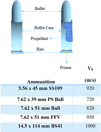 | ||
| Fig. 5 Components of small arms ammunition and their corresponding velocities.19 | ||
(a) The primer.
(b) The cartridge.
(c) The propellant.
(d) Any ancillaries (such as propellant packing).
(e) The projectile (bullet).
In discussing the failure phenomenon of armour materials, the projectile type and its geometry become the prominent factors because the failure behaviour of body armour materials largely depends on the geometry of the projectile tip, the velocity of the impact and the relative dimensions of the target and the projectile. In the early days of firearms weapon development, the initial shape of the projectiles was a simple sphere, but this shape cannot attain an efficient ballistic profile, so in the later stages of development the inefficient spherical shape was replaced by an ogival shape for increased aerodynamic stability and reduced flight drag. Fig. 6a–d illustrate the various shapes of bullets that are extensively exploited in small arms.
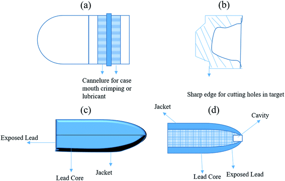 | ||
| Fig. 6 (a) Round-nosed bullet; (b) wadcutter bullet; (c) jacketed bullet; (d) semi-jacketed hollow-point bullet. | ||
B. J. Heard et al. elaborated various other shapes, such as the wadcutter (flat-nosed bullet with a sharp shoulder), the spitzer (a German term applied to an elongated ogival bullet with a sharp point), the hollow point (a semi-jacketed bullet nose, which has a cavity) and Dum–dum (a 0.303′′ bullet design developed in the Indian arsenal of Dum Dum in 1894).26 The destructive effects of the bullet shape and geometry on ballistic armour were studied in detail by T. G. Montomery et al., who reported how, at higher velocities, a pointed bullet does not decelerate, and is comparatively more stable than a blunt-shaped bullet.27 In this study, it was found that at lower velocity, the pointed bullet struck to the target at an angle, which demonstrated the extraction of a higher impact energy. In contrast to all these phenomena, the authors of the report pointed out that with the increase in the thickness (e.g. in their study, the number of plies) of the target, the difference in penetrating energy as a function of projectile shape was less noticeable. In addition to this remark, the effects of the projectile shape and geometry are further analysed in the present paper in the subsequent sections related to the failure mechanism of various body armour materials.
1.3 Metallic armour (steel armour)
Jared Diamond wrote that “historical inequalities have cast long shadows on the modern world, because the literate societies with metal tools have conquered or exterminated the other societies”.28 This conjecture of Jared Diamond has been applicable around the world since the dawn of mankind. The desire for survivability has attracted significant attention to the development of protective armour to protect against the evolution of arms, from combat axes, to swords, light lances, daggers, arrows and later high energy projectiles, firearms and large-calibre missiles. However, Bashfor Dean illustrated in his book Helmets and body armour in modern warfare (Published in 1919) that “Helmets and body armours are considered as beautiful objects and its technical side is not much explored for individual's knowledge”.29 World War I marks the point when the contemporary dimensions of armour materials and designs evolved to the current form seen in advanced modern protective materials.In the ancient world, iron and steel were the most explored materials for armoured protection against arms and weapons. It is a challenge to clearly mark the exact transition between the iron and bronze age or to say which came first, but Dr John Percy articulated in favour of iron in his inaugural address as President of the Iron and Steel Institute in May 1985 when he stated, “It has always appeared to me reasonable to infer from metallurgical considerations that the age of iron would have preceded the age of bronze. The primitive method, not yet wholly extinct, of extracting iron from its ores is a much simpler process than that of producing bronze, and this requires a much less advanced state of the metallurgical arts. In the case of iron, all that is necessary is to heat the ore strongly in contact with charcoal; whereas in the case of bronze, which is an alloy of copper and tin, both copper and tin have to be obtained by smelting their respective ores separately, which then have to be subsequently melted together in due proportions and the resulting alloy cast in moulds, which requires considerable skill in their preparation”.30
Our ancestors also utilized malleable iron, which was discovered in western Asia and in the northern part of Africa. This form of iron was produced in a furnace, which was similar in style to the nineteenth century “air bloomeries”.31 These primitive furnaces were simple conical structures that contained one small and one large opening for the admission of air and for the escape of combustion product, respectively. The furnace was further erected high on the ground to assist the combustion by the flow of air. The process of reduction resulted in an imperfect malleable iron mixed with scoriae and unreduced oxide. Other than malleable iron, cast iron was another form of iron that was utilized during the antiquarian period. Cast iron was discovered accidently due to the high demand for iron, where, to meet the increased demand, the size and height of the smelters of the bloomeries were increased, which caused a prolonged exposure of the ore to charcoal in the bloomeries, and this led to a higher state of carburation, which resulted in an unknown product being formed, i.e. cast iron.31 The fabrication and reduction of iron ores to useful products was known to all contemporary civilizations of ancient Egypt, including the Chaldeans, Babylonians and Assyrians. The Greeks were the logical successors in the pursuit of iron, and indeed many iron antiquities have been found to date, including iron helmets, neck guards in chain armour and fragments of breastplates unearthed in city of Thebes, which illustrate the prowess of the Greeks for working with iron.30 Iron is considered a revolutionary metal that transformed various civilizations around the world due to its availability, ease of fabrication and high strength. The longing for survivability led mankind to employ iron in numerous forms, arrangements and designs for personal protection after the advent of arms and weapons. The following forms are the most exploited body protection systems around the world against lances, swords, arrows and even firearms and ammunitions.
(a) Scale armour: consists of small metal scales, with the size in the range of 2.8 × 1.4 cm to 8 × 54 cm plates (Ex. coat of scale armour).
(b) Mail armour: fabricated via interlinked small iron rings to form a mesh (Ex. hauberk, chain mail, byrnie).
(c) Plate armour: made up of plates of iron or steel (Ex. cuirass, laminated cuirass, corselet).
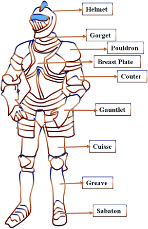
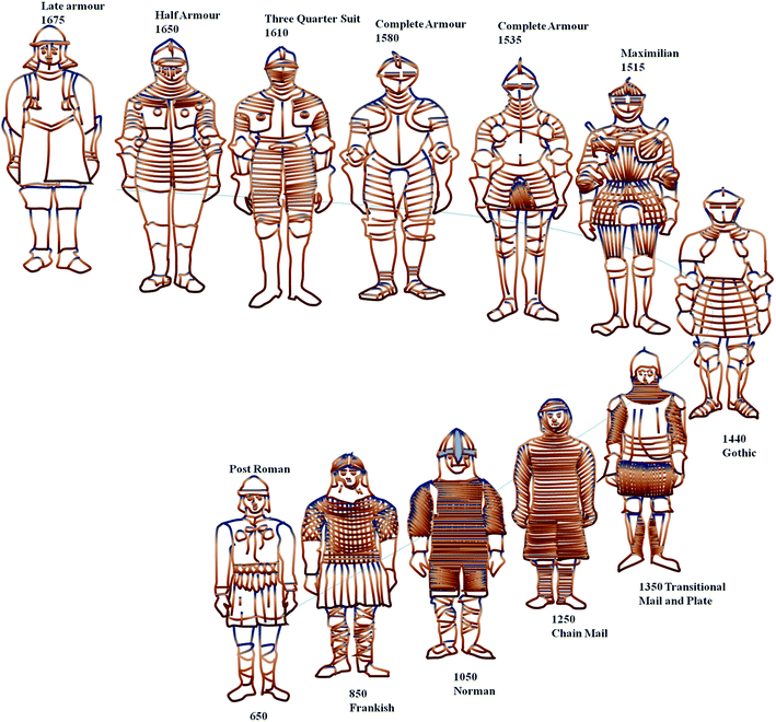
The fabrication of scale armour was relatively easy and required minimum skill and cost. Therefore, its use was quite ubiquitous for hundreds of years for the Roman Empire. In the Middle Ages, chain mail was quite acclaimed but its cost of manufacturing was high due to the evolution of new materials and techniques. The mail possessed the ability to prevent penetration by swords, lances and arrows, but it could not stop casualties or deaths from blunt trauma and blow energy. To circumvent trauma-related casualties, between 1200 and 1400 A.D., mail armour was reinforced with bands or steel plates.8 The use of chain mail was further diminished due to its high manufacturing cost and its inadequacy against cavalry charges with lances, impact warfare and high-powered crossbows. By about 1400 A.D., soldiers were completely attired with plate armour, as illustrated in Fig. 7. Plate armour was at its highest development phase during the end of the fifteenth century and continued in the same form till the mid-seventeenth century. Simultaneously, handguns, firearms and powder explosives improved prominently, which lead to the development of much heavier body defence systems compared to previous developments.32Fig. 8 illustrates the chronological development of body armour systems in Europe.29
There is evidence that army personnel were not happy with the weight of personal protection systems in the late sixteenth century, which prevented them taking a more active participation in the battlefield. In spite of various physiological stresses posed by heavy armour, various other reasons were also responsible for the reduced usage of personal protection systems, including changes in war tactics, such as the need for a manoeuvring army to cover long distances in a short time, which was challenging in heavy personal armour.29 In later wars, armour was used more sporadically, mostly in the form of body defence, helmets or shields. By the time World War I broke out in Aug 1914, even though, a dozen or more types of armour were available in the early 1900s, soldiers were not adequately attired with any defence for the body, albeit helmets were manufactured on a priority basis. Steel continued to be a preferred material for body armour and later for structural tank armour. Table 7 shows the evolution of steel in armour. The modern armour era for body protection evolved after World War II and the Vietnam War and was then further remodelled by the advent of armour grade ceramics and fibres.
| Steel armour | Time period | Drawbacks |
|---|---|---|
| Cast iron | Before World War II | Insufficient armour protection |
| Face hardened steel armour | World War II | Brittleness and manufacturing difficulties |
| High hardness steel | 1960 | Brittleness and inappropriate for structural applications |
| Dual hardness steel | 1964 | Machining and forming difficulties |
| Heat treatable dual hardness steel | 1967 | Expensive attachment process of rear plate |
| Unidirectional solidified wrought steel | 1970 | Scaling with desired properties was difficult |
| ESR steel | 1972 | Reduced toughness at low temperature, inappropriate for structural applications |
| Steel plate wrought ESR | 1976 | Inappropriate for structural applications |
| Previous versions of steel with modifications and the utilization of advanced materials, such as composites, laminates, ceramics, fibres | Beyond 1976 | Complex manufacturing process, degradability associated with various armour fibre laminates |
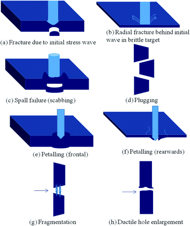
It has been observed that very high compressive waves accompanied by instantaneous release waves are generated at the surface of a penetrator (e.g. the projectile) and target (e.g. the armour). In addition to the compressive and release wave, another release wave is produced due to the reflection of the compressive wave from the free surface of the target materials.35–40 The phenomenon of spalling of the target plate has been noticed when the compressive stresses are large enough compared to the tensile stress originating from both the release waves. This is the first failure mode that can ensue in a metal target used to protect against high energy projectiles. In addition to this mechanism, another phenomenon can also prevail during the catastrophic target failure of metallic armour. For instance, when a projectile strikes the surface of the metal armour, a large strain builds around the periphery of the projectile and, further, a fracture may occur at that position if the developed strain exceeds a certain critical value. Subsequently, as the penetration of the projectile proceeds, tensile stress can be generated at the free surface of the target material, which causes adiabatic plugging if the projectile geometry and materials properties are such that the rate of heat generation by plastic deformation is greater that heat dissipation by conduction. The temperature rise in the local region of deformation reduces the material's flow stress, thereby permitting further deformation to occur. The process accelerates until fracture is initiated and plugs form through the entire thickness of the target.33 The penetrating projectile and target during a high-velocity impact encounter various physical phenomena based on their characteristics and properties, as presented in Table 8.35
| Phenomenon observed in the target | Characteristics of the target |
|---|---|
| Wave propagation (elastic, plastic, hydrodynamic, normal bending, shear stress, hydrostatic pressure) | Bulk and shear Moduli |
| Plate deformation (elastic, plastic) | Strength |
| Cracks (initiation, propagation, arrest) | Density |
| Petalling | Thickness: Semi-infinite |
| Plugging, spalling and scabbing | Thick |
| Frictional effect | Intermediate |
| Fragmentation, vapourization and phase change | Thin |
| Phenomenon observed in the projectile | Characteristics of the projectile |
|---|---|
| Wave propagation | High velocity |
| Permanent deformation | Sub-ordnance velocity (25–500 m s−1), Nominal Ordnance range (500–1300 m s−1) |
| Fracturing | Ultra Ordnance range (1300–3000 m s−1) |
| Fragmentation | High density |
| Heating | Length in dimension of penetration |
The analytical method utilized for evaluating the dynamics of the penetration mechanism involves an empirical or quasi-empirical model, an approximate analytical method and a numerical method, where these methods are generally explained on the basis of either the conservation of momentum or on the energy balance.41 The theories derived from a momentum balance are typically used for thin plates, whilst the energy balance theories are utilized for thick and moderate thick plates. The analytical approach for evaluating the ballistic response of a metallic system has been substantially explored by various authors and researchers for a variety of penetration configurations.41–47 The simplest ballistic data correlations were developed by de Marre, Grabarek and Thor, as discerned in eqn (1)–(3) below.48–50 T. W. Wright illustrated that these correlations are appropriate for the interpolation and extrapolation of a small data set but they do not consider non-dimensional forms and material properties.51 Later, several efforts were made to modify de Marre's formula to empirically derive a more general form of the equation to predict the penetration phenomenon, as outlined in eqn (4)–(6).
de Marre:
| mV12 = Cdβtα | (1) |
Grabarek:
 | (2) |
Thor:
| VS − VR = CtαmβVSγ | (3) |
H. Berthe:
| mV12 ∼ td2 | (4) |
Zener & Holloman:
| mV12 ∼ t2d | (5) |
Curtis Taub:
 | (6) |
S. Jacobson proposed different energy relations for plugging or piercing phenomena, as below:41
| Eplug = force × dis. ≈ Πdtγst | (7) |
 | (8) |
They further modified eqn (7) and (8) as below:
 | (9) |
 | (10) |
To obtain the critical value of the ratio of thickness of the target plate to the diameter of the projectile  they solved the equation by equating both the energies required for plugging and piercing to happen (Eplug = Epiercing), which rendered the following relations:
| γs ≈ 0.6γflow | (11) |
 | (12) |
 | (13) |
This analysis implies that once the ratio of  exceeds 0.42, then piercing would be expected, whereas below this value, plugging would be anticipated. This is the simplified methodology to represent the penetration phenomenon of a projectile into a target, while various other models have also been reported, which also exhibit fairly accurate results (within 15%).46,47
1.4 Monolithic ceramic and ceramic composite armour
The term ceramics is derived from the word “Keramikos”, implying to “burn things”. Ceramics encompass all inorganic materials, ranging from crystalline to a vitreous glass, but excluding metal and metal alloys.2,19 Ceramics for body armour applications are exploited either in the form of monolithic plates or a composite metal ceramic system confined by ballistic nylon and high-performance fibre lining and laminates.52 Ceramics are one of the most prominent materials for ballistic applications due to their high compressive strength, low density and high hardness. The utilization of brittle materials as a body armour was first witnessed in 1918, when Major Neville Monroe-Hopkins explored the possibility of using a thin layer of enamel on steel plate.18 Later, Goodyear Aerospace promoted ceramics as an armour material by filing a patent in 1970 for a ceramic faced armour composed of alumina facing. In the course of development of armour grade ceramics, alumina has been extensively explored, regardless of its elevated density compared to other oxide and non-oxide ceramics, due to its high physical properties and performance, low processing cost and its ability to be manufactured via a variety of methods, such as slip casting, pressing and injection moulding.53,54 In contrast to oxide dense ceramics, non-oxide ceramics, such as boron carbide (B4C), silicon carbide (SiC), silicon nitride (Si3N4) and aluminium nitride (AlN), including their binary systems, render low density and high mechanical properties (hardness, Young modulus and strength) but the manufacturing cost (hot pressing) curtails their utilization in armour application. Recently, reaction bonded silicon carbides and boron carbides have been other noticeable developments that have demonstrated good prowess for manufacturing large-size products at low cost but with high physical properties.55 W. A. Gooch Jr extensively detailed the development of armour grade ceramics, which have been utilized in a wide range of military platforms and applications in recent years (Table 9).56 Simultaneously, extensive research was carried out to into the possibility of utilizing various ceramic materials and combinations against a variety of high impact projectiles, as listed in Table 10.| Advancements in ceramic armour |
|---|
| Tandem ceramic armour |
| Hot isostatically pressed encapsulated ceramics |
| Pelletized ceramic armour system |
| LIBA™ (light improved ballistic armour) |
| SMART™ (super multi-hit armour technology) |
| Corbit™ 98 |
| High-density ceramics |
| Functionally graded metal/ceramics |
| Process | Ceramic type | Backing plate | Type of projectile | Mode of penetration |
|---|---|---|---|---|
| Pressure-less sintering process | Al2O3 & AlN | Al-5083 wrought alloy | 7.62 Dragunov Rifle (840 m s−1) | Depth of penetration (DOP) [ref. 62] |
| Spark plasma sintered process | B4C, SiC–5 wt% B4C, SiC–2.5 wt% AlN–3 wt% C | — | 7.62 × 54 B32 API Mk2 (616–883 m s−1) | V50 [ref. 63] |
| Hot pressing | Ti3SiC2 | Al | 9 × 19 mm Parabellum type (TC 95) | — [ref. 64] |
| — | SiC–Al2O3, SiC–Si3N4–Al2O3, SiC–Si3N4–SiAlON | Commercial available aramid and polyethylene fabrics | 5.56 × 45 mm SS109 NATO Ball FMJ steel tip ball | DOP [ref. 65 and 66] |
| 7.62 × 39 mm Russian ball FMJ mild steel core | ||||
| 7.62 × 51 mm NATO ball FMJ lead core | ||||
| 0.308 win Winchester 7.62 × 51 mm Ball FMJ | ||||
| 7.62 × 54 R LPS Russian ball LPS streamlined ball steel core | ||||
| 0.308 Lapua 7.62 × 51 mm Ball FMJ | ||||
| 7.62 × 63 mm APM 2 | ||||
| Armour-piercing M2 FMJ WC core | ||||
| Sintering | 10% zirconia toughening alumina & 95% alumina ceramic | Medium steel | Tungsten long-rod projectile | DOP [ref. 67] |
| Pressure infiltration method | B4C/2024 Al, with 55% volume fraction of B4C | — | 7.62 × 51 mm armour-piercing bullet | — [ref. 68] |
| — | B4C | Radial confinement by steel with aluminium alloy backing (Al 6063-T6 & Al 7017 | 7.62 armour-piercing bullet (600–820 m s−1) | [ref. 69] |
| Plasma spray technique | Al 2024-T351 | — | 9 × 19 mm Parabellum bullet (370 ± 10 m s−1) | DOP [ref. 70] |
| Al 6061-T 651 | ||||
| Al 7075-T651 | ||||
| Coated with Co–Mo–Cr and ZrO2 | ||||
| — | Convex curved Al2O3–4 wt% Nb2O5 | 6061-T6 aluminium alloy | 7.62 × 51 mm NATO ammunition bullet | DOP [ref. 71] |
| Cold pressed method | Al2O3 ceramic powder | Polycarbonate & Al6082-T651 | 22 mm bore 2 m barrel single stage gas gun (375 m s−1) and modified FFV core bullet (approx. 900 m s−1) | DOP [ref. 72] |
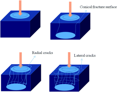
The combat responses of ceramics are determined by utilizing V50 (the projectile velocity at which there is a 50% probability of penetration) and the depth of penetration. The V50 methodology is employed for testing the finite thickness of ceramic armour backed by a metal or composite against small calibre and fragment-type kinetic energy (KE) threats, whilst the depth of penetration is utilized for understanding the mass efficiency of ceramics relative to the thick metal backing against medium and large-calibre KE as well as against long-rod penetrators and shape charge jets.93 The general phenomenological descriptions of the penetration process in ceramics are illustrated in Fig. 10, which can be explained via two timescales. The first timescale can be described as a shock wave period, which includes the time required for stress wave reflections to pass through the armour plate, and a second timescale, which encompasses the subsequent structure response period.92 In the first timescale, when the projectile strikes the ceramic surface, a circular ring-like tensile crack develops at an angle of 25–70° from the normal surface, which propagates along the principle stress plane.40 These circles around the centre of contact with the projectile spread to form a group of shallow co-axial cylindrical cracks that propagate to the distal boundary and form Hertzian-type conoid crack by coalescence of the waves.41,92 At this instance, the structural response period determines the failure mechanism of the ceramic system. If the ceramic is not backed and if the shock exceeds its Hugoniot elastic limit (HEL), the ceramic would be perforated via plugging.94 In the case of a complete failure, projectile erosion is a prominent factor and largely defines the performance of any armour grade ceramics. It has been observed that the time required for perforating (dwell time) the plate largely influences the penetration efficacy of the ceramic armour.
If the projectile is backed, the ceramic plug moment will be restricted, which results in the start of microcracks forming. At this point, the pulverization of ceramic materials is attributed to the comminuted zone. If a projectile attempts to penetrate through the comminuted ceramic, the rate of projectile erosion is enhanced and further causes the conoid ceramic to distribute the concentrated impact load over a large area of the backup plate. The backup plate is deflected under the applied load, and the powdered material flows radially outward and rearward, and thus the amour subsequently fails in this condition.95
Significant numbers of experimental studies have been performed to understand the failure mechanism of ceramic armour under a variety of loading conditions. In contrast to the meso-scale assessment of ceramic failure and its validation via an analytical method, T. Antoun et al. showed that the majority of experiments actually investigated the response of the ceramic during and after the penetration phenomenon or included the measurement of static (toughness, hardness, yield strength) or dynamic (Hugoniot elastic limit, rate effect on yield strength) properties in strength-dominating regimes.96 However, various analytical methods have been developed to elaborate the more intrinsic mechanisms involved in the response of ceramics against ballistic impact, such as:96
(i) Constitutive models (such as the comprehensive mechanical model).88,97–102
(ii) Meso-mechanical models.103–108
(iii) Adaptive discrete continuum models.96,109
Among the above-stated models, the comprehensive mechanical model (constitutive model hypothesis) of Johnson and Holmquist has been highly recognized due to its sophisticated description of the material response under loading and unloading stimuli. Johnson and Holmquist's model contained three stages of development represented by three models, termed as JH-1, JH-2 and JHB. A brief description of these entire models is provided in Table 11.
| JH-1 [ref. 110] | JH-2 [ref. 111] | JHB [ref. 112] |
|---|---|---|
| Pressure dependent strength, damage and fracture, bulking and strain rate effect | Under the condition of increasing plastic strain, a gradual softening is noticed, which is attributed to the damage accumulation (D > 0) | The description of this model is similar to the JH-1 except that it contains an analytical description of the strengths (intact and failed) and analytical function for the failure strength. It also accommodates the phase change of the material |
| Instantaneous softening occurs when the damage, D = 1.0 | Pressure and strength components are normalized with the pressure and strength component of the Hugoniot elastic limit, which renders many of the dimensionless constants | |
| It uses multiple linear segments | The strength and damage are considered as analytical functions of the pressure and other variables |
According to the JH-2 model, the hydrostatic pressure before fracture begins (D = 0) is given by:
| P = K1μ + K2μ2 + K3μ3 | (14) |
 (ρ = current density; ρ0 = initial density).
When the damage begins to accumulate, Johnson and Holmquist introduced an additional incremental pressure due to the bulking, (pressure increase and/or volumetric strain increase) phenomenon. Further, the updated ΔP can be solved as eqn (16):
| P = K1μ + K2μ2 + K3μ3 + ΔP | (15) |
 | (16) |
1.5 Fibrous armour
Fibres are a conspicuous method of protection against heat, cold and other environmental conditions. The demand for lightweight wearable ballistic protection systems simulated research activity to develop body armours made of fibres and fabrics. It could be assumed that fibrous armour could provide the most comfortable, compatible and obtrusive method of protection on a battlefield. This conjecture regarding fibres was given more credence by Carothers at DuPont in the early 1930s, when he invented nylon fibre, which he demonstrated to have a strength of 0.6 to 0.7 N/Tex.113 Despite, nylon manifesting outstanding strength, at that period of time it was not extensively exploited as a ballistic fibre due to its loss of modulus and other physical properties when exposed to high humidity conditions. Over time, various other fibrous materials, including fibre glass, polyester, rayon, silk, acetate yarn and isotactic polypropylene, have been developed and explored for ballistic protection applications, but none of them have accorded satisfactory results.114–120 The development of a liquid crystalline aromatic polymer at DuPont in 1965 emerged as a benchmark in the history of fibrous armour systems, with this polymer recognized now by its more famous trademark name: Kevlar®. In the last two decades, a wide variety of high-performance fibres, like Twaron® (para-aramid), Kevlar® (polyaramids), Spectra® (polyethylene fibres), Technora® (aramid fibres), Zylon® (poly(p-phenylene-2,6-benzobisoxazole)) and Vectran® (aromatic polyester), have been exploited for their ability to stop high energy projectiles, but Kevlar® (polyaramids) and High Molecular Weight Polyethylene (HMWPE) have also been utilized as ballistic armours for a broader range of arms and ammunitions.23,121,122 A more detailed consideration of Kevlar and HMWPE are outlined in the subsequent section.| Kevlar type | Characteristics | Strength of yarn (GPa) | Initial tensile modulus (g d−1) | Elongation at rupture (%) |
|---|---|---|---|---|
| Kevlar® 29 | 720D, 1000D, 1500D | 2.9 | 525 | 3.5 |
| Kevlar® 49 | 1420D, 2840D | 2.9 | 950 | 2.5 |
| Kevlar® 68 | Medium type between 29 and 49 | 3.1 | 780 | 3.0 |
| Kevlar® 119 | High durable | 3.1 | 430 | 4.11 |
| Kevlar® 129 | High tenacity | 3.4 | 750 | 3.4 |
| Kevlar® 149 | Ultrahigh modulus | 2.3 | 1100 | 1.3 |
The utilization of Kevlar as a ballistic protection began with the National Institute of Law Enforcement and Criminal Justice, the National Institute of Standards & Technology and the Office of Law Enforcement Standards. The evolution of body armour by NIJ was planned in four phases, with the first phase being the testing of Kevlar® fabric to determine whether it could stop a lead bullet. The Kevlar® vest was first time tested at the Aberdeen Proving Ground, Maryland, USA, on 100 goats against 0.22 and 0.38 calibre pistols. The obtained results were outstanding; all the goats survived and suffered nothing worse than bruises. In 1975, 5000 Kevlar® vests were distributed to 15 police departments throughout the United States.18 More recently, Kevlar® has gone beyond its economic state in 1975; now estimated global demand for aramid fibre is projected at around US$4.7 billion.129 Despite its high mechanical properties, Kevlar® exhibits a time-dependent mechanical behaviour. Its physical, chemical and environmental effects have been extensively explored to understand its ability to retain its mechanical property under adverse conditions. Mead et al. reported that Kevlar® 29 losses 23% of its strength by being aged for 2 weeks at 100% room humidity (RH) and 150 °C, and, simultaneously, a 27% reduction was observed in smog after 26 weeks. Morgan et al. related the mechanical integrity and oxidation and hydrolytic stability to the impurities generated due to the processing constraints.130 They described how a small amount of impurities such as the ash content or H2SO4 residue, can accelerate chemical degradation and moisture absorption. It has been noted that Kevlar® fibre losses 40% of its efficacy against 0.22 calibre bullets under the wet conditions.130
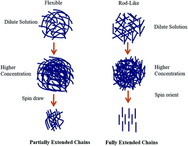
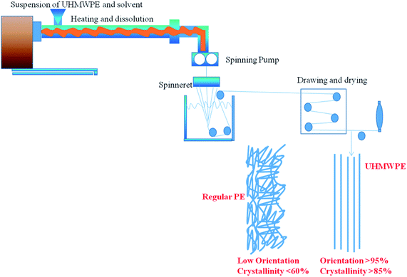
The ballistic efficacy of UHMWPE is generally explored in the composite form due to its low coefficient of friction for individual fibres, which results in interyarn movement under ballistic conditions. In order to improve the ballistic efficacy of UHMWPE, various strategies have been employed for a variety of configurations.152–162 N. Bhatnagar et al. demonstrated that body armour materials based on polymeric systems are prone to environmental degradation under various stimuli, such as temperature, humidity, radiation and ultraviolet light.163 A. L. Alves exposed UHMWPE to the weather and gamma radiation to evaluate its ballistic response against a 9 mm calibre projectile.164 They demonstrated that, a composite plate exposed to the weather did not perforate, whereas a 25 kGy dose and all 250 kGy doses were perforated. They described how the failure mechanism of the fibre follows a process of fibre breakage, matrix cracking, fibre-matrix debonding and delamination, simultaneously or separately. The interfacial resistance was further found to be reduced due to oxygen diffusion among the layers due to the weathering or gamma irradiation, which resulted in oxidative degradation. The high-performance fibre durability was extensively elaborated and compiled in a report “understanding and improving the durability of textiles”.165
 | (17) |
 | (18) |
 | (19) |
 | (20) |
 | (21) |
 | (22) |
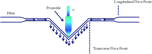
In order to understand the failure mechanism of a single ply of fabric, Cunnif et al. noted that the velocity of the projectile deflects the principal yarn at the point of contact, whereas orthogonal yarn was pulled out of the original fabric plane. The orthogonal yarn experiences a similar wave propagation as the principle yarn, and the movement between both the yarns generates friction, which results in bowing and misalignment of the orthogonal yarn.191 In another study, Y. Duan et al. described the impact response of fabrics and depicted that fabrics offer a reaction force when a projectile strikes the fabric. In this condition, they postulated the energy conservation hypothesis by assuming negligible energy dissipation due to the projectile deformation, while intermolecular friction, wind resistance and acoustic losses were not considered in the analysis.192 The governing equation for energy transfer between the projectile and fabric was given as below:
| ΔEpk = Eys + Eyk + Ef | (23) |
 | (24) |
(i) 3D non-interlaced fabrics: 3D interlaced fabrics manufactured via laying fabrics on a plane without creating any kind of interlacement. These kinds of fabrics can be further classified as: uniaxial (0°), biaxial (0°/90°) and multiaxial (0°/90° ± 45).
(ii) Multi-stitched 3D woven fabrics: multi-stitched fabrics can be obtained by stitching 2D woven fabrics in the out-of-plane direction via a lock stitch technique (warp-0°, warp and Weft 0°/90°) and warp, weft and bias 0°/90 ± θ).
(iii) 3D fully interlaced woven fabrics: in order to achieve such fabrics, warp yarns are interlaced with weft yarn, with each layer based on the weave pattern in the in-plane principal direction, whereas the z-direction yarn is interlaced with warp yarn via the out-of-plane principal direction.
The authors also defined a few more 3D fabrics, such as 3D orthogonal woven fabrics, multi-axis 3D woven fabrics, 3D braided fabrics and 3D nonwoven fabrics. In addition to the 3D fabrics, a multi-ply system is another strategy to enhance the ballistic proficiency of high-performance fabrics. However, P. M. Cunnif did not concur with the statement stated above because he hypothesized that when a projectile hits a multilayer system, the transverse direction deflection is constrained by the subsequent ply, which in turn augments the tensile gradient. Therefore, the target materials fail with lower velocity impacts.191 He also reported that the transverse shear and compressive system are enhanced with further increases in the ply layers. Consequently, shear and compressive failure become pre-eminent with a multi-ply system. In contrast to these findings, Wang et al. suggested that the overall effectiveness of a multi-ply system depends on: (i) the ply orientation; (ii) the layering sequence of plies; (iii) the ply group combination within the plane. They reported that angled fabric panels demonstrate a higher energy absorption compared aligned fabrics, whereas for eight ply systems, the performance of the sub-ply group determines their energy absorption capacity.196 Therefore, it can be concluded that the most effective and optimum design of the fabric will be when the ballistic threats and wearer conditions are properly anticipated and evaluated (Fig. 13).
1.6 Nanomaterials for ballistic applications
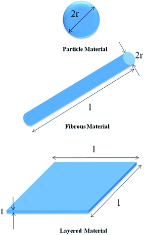
According to E. T. Thostenson et al., nanotechnology is defined as the creation, processing, characterization and utilization of materials, devices and systems with dimensions in the order of 0.1–100 nm and that exhibit novel and significantly enhanced physical, chemical and biological properties, phenomenon and processes due to their nano-scale size.197 The properties of composites developed by reinforcing nanomaterials are broadly dependent on the surface area/volume ratio and the interphase characteristics between the matrix and nano-reinforcement. E. T. Thostenson described three categories of nano-additives: particles (silica, organic and inorganic particles), layered materials (graphite, etc.) and fibrous material (nanofibres and tubes), as illustrated in Fig. 14.Among all the nano-additives, carbon nanotubes (CNTs) render unparalleled properties, including chemical, mechanical, electronic and magnetic properties.198 CNTs are rolled hexagonal carbon networks capped by pentagonal carbon rings and categorized as single walled carbon nanotubes (SWCNTs) and multiwalled carbon nanotubes (MWCNTs).199 MWCNTs were first engineered by S. Lijima from a carbon structure via the DC arc discharge evaporation of carbon in an argon-filled vessel, where the obtained carbon needles possessed diameters of 4 to 30 nm, with lengths up to 1 μm.200 S. Lijima et al. and Bethune et al. simultaneously reported the formation of SWCNTs by introducing a metal catalyst to the carbon arc chamber.201,202 In contrast to the findings of Lijima and Lijima et al., M. Terrones claimed in his review that MWCNTs and SWCNTs were first imaged by Endo in the mid-1970s, where he varied the experimental conditions to obtain HRTEM images of a carbon fibre produced by the pyrolysis of benzene and ferrocene at 1000 °C.199,203 In recent years, CNTs have been produced by a variety of processes, such as arc discharge, the pyrolysis of hydrocarbons over metal particles, laser vaporization of a graphite target, solar carbon vaporization and electrolysis of carbon electrodes in molten ionic salts.199
K. Mylvaganam et al. described the energy absorption capacity of carbon nanotubes under ballistic impact, and investigated SWCNTs [(27, 0), (18, 0) and (9, 0)] of radii 10.576, 7.05 and 3.525 Å with approximate lengths of 75 Å under the condition of one and both ends of a CNT fixed.204 To simulate the bullet condition, a piece comprising 1903 atoms with dimensions of 35.67 × 35.67 × 7.13 Å was utilized with varying speeds of 100 to 1500 m s−1. It was ascertained that with an increase in the bullet speed, the energy absorption efficiency decreases with the increase in the relative height of the bullet when one end of the CNT was fixed; while for the CNT fixed at both ends, the energy absorption capacity of the CNT was dramatically reduced beyond the speed of ≈1000 m s−1. In another study, the same group considered the ballistic proficiency of analogous CNTs against bullet speeds between 1000 and 3000 m s−1.205 In this report, they explored the bullet resistance capacity of CNTs (fixed at both ends) by considering the force, energy, momentum and velocity variation in the time domain. They postulated that the speed of the bullet will start decreasing from the moment it strikes the CNT target, while the velocity would be zero if the bullet was embedded in the target or at higher velocity, the bullet could penetrate the target. In all the conditions, the energy conservation hypothesis was applied and it was speculated that the highest speed a CNT target could withstand was a function of the relative impinging location (ρ = h/L, where h = distance between the bullet impinging point and the end of the nanotube, and L = length of the tube). The energy absorption capacity was observed to be higher with long lengths and reached a maximum at ρ = 0.5.
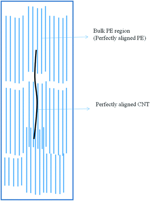
Ruan et al. has been acknowledged for utilizing MWCNTs to enhance the properties of high-performance UHMWPE and achieved a 150% improvement in strain energy density accompanied with an enhancement in ductility by 140% and tensile strength up to 25%.206 The same group exploited the possibility of gel-spinning UHMWPE with carbon nanotubes and reported that the incorporation of 5 wt% MWCNT enhanced the tensile strength by 18.8% and the ductility by 15.4%, together with a 44.2% improvement in the energy to fracture, compared to the pristine UHMWPE.207 The augmented mechanical properties were attributed to the increased crystalline temperature by virtue of the nucleating effect of the MWCNTs. The incorporation of 5 wt% of CNTs in UHMWPE during the gel-spinning process at lower drawn ratios leads to clusters of about 1 μm diameter being formed. The drawn ratio was found to be a prominent parameter to define the orientation of CNTs along with the UHMWPE fibrils and it was noted that as the drawn ratio increases, CNTs are pulled out from their cluster regions, resulting in a striking change in the fibre morphology, as illustrated in Fig. 15.208 CNTs are extensively exploited to engineer polymer matrices for augmenting various properties, but agglomeration due to the strong attractive forces between the CNTs and interfacial adhesion with the polymer matrix are two paramount challenges for CNT-based polymer nanocomposites.209 To circumvent these challenges, various methodologies, such as stirring, sonication, high shear mixing, calendaring methods and functionalization of the CNTs have been successfully employed. M. Rehman et al. tailored CNTs with an amino group to access the ballistic proficiency of E-glass/epoxy composites.210 The ballistic responses of the composites were evaluated using a spherical steel projectile with a diameter of 7.90 mm and speed range of 240 to 380 m s−1. The obtained results demonstrated that the composite containing 0.3 wt% of functionalized MWCNTs possessed the ability to embed the bullet in the speed range of 301 m s−1 to 307 m s−1, while 0.5 wt% of CNTs in the composite achieved an analogous phenomenon in the speed range of 301–319 m s−1.
1.7 Bio-mimicked armour material: a futuristic design
As we have been able to achieve unprecedented properties in artificial materials, then why should we spend effort discerning the nature of natural materials? Meyer answered this question by stating, “We have used our ingenuity to the maximum, but one way to overcome this is to look at nature for new design and concepts”.211 Natural exoskeletons have acquired a remarkable and ingenious combination of mechanical properties, such as strength, stiffness and toughness.212–214 In the last few decades, a diversity of biological materials, their structure–property relationships, complexity, multifunctionality and a hierarchy of materials, such as butterfly wings, mollusc shells, bones, spider silk, gecko feet, lotus leaves, plant cell walls, mussel byssi, Venus's Flower Basket, brittle star optic and flexible armour of fish, have been extensively exploited for their interdigitating hierarchal structures,215,216 but dominance over natural design is yet to be achieved in synthetic materials. J. Aizenberg et al. notably exemplified this complementary research direction when they managed to mimic some natural materials in a three-step process they described as follows:216(a) The first step involves elucidation of the structure and property relationship for the selected natural materials.
(b) The second stage covers evaluation of the physical/chemical principles of the structure–function relationship on an experimental and theoretical basis.
(c) The last step addresses the pathways for manufacturing and synthesising the natural properties in an artificial system by considering the engineering constraints and costs.
It has been contemplated that almost all the research approaches in this field follow an analogous pathway to that described by J. Aizenberg et al. The artificial design and manufacturing of biological systems for the development of human body armour, e.g. by mimicking spider silk, flexible fish armours and mollusc shells, have fascinated researchers and attracted great attention. Spider silks display a remarkable combination of strength, toughness and robustness combined with biodegradability and biocompatibility.217,218 The structural hierarchy of spider silks can be categorised from the macro to the nano, as described by I. Su et al.219 Spider silks are composed of bundles of nanofibrils confined in an amorphous matrix, and the orientation of these fibrils defines the anisotropic mechanical characteristics. At the nano-scale level, these bundles are comprised of networked architectures of nanocomposites, resulting in a non-linear stiffening of silk when it is under a stretched condition. These nanocomposites are a combination of stiff β-protein nanocrystals and the disordered amorphous phase. A. Rising et al. reported that all silks are composed of proteins that consist of an extensive repetitive central part flanked by a smaller non-repetitive domain.220 They also illustrated that the use of an organic solvent or other chaotropic agents and a non-physiological coagulation bath are the prime challenges that curtail the formation of the desired natural folding of silk fibroins. In addition, in vitro reproducibility of the rheological properties of the silk dope and physical stress is another cumbersome process, which hinders the acquisition of silk's mechanical properties to the artificial materials.
Mollusc shells are another prominent material that can be mimicked to fabricate body armour due their unparalleled combination of multi-hit capability, toughness and strength. “Mollusc” refers to the word “soft bodies” and is essentially manifested as a sea shell.221 The mollusc phylum contains seven different taxonomic classes, including Aplacophora, Polyplacophora, Cephalopoda, Gastropoda, Bivalvia, Scaphopoda and Monoplacophora. Among these seven taxonomies, only five (Cephalopoda, Gastropoda, Bivalvia, Scaphopoda and Monoplacophora) are shells bearing a mollusc;222 whereas, on the basis of the structure, mollusc phylum can be classified as: nacre (columnar and sheet), crossed lamellar (plywood like), prismatic (polygonal columns), foliated (long thin crystals in overlapping layers) and complex cross lamellar, as illustrated in Fig. 16.223
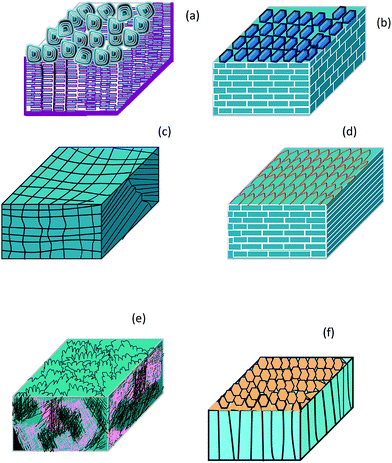 | ||
| Fig. 16 (a) Columnar nacre; (b) sheet nacre; (c) crossed lamellar aragonite (d); foliated calcite (e) complex crossed lamellar; (f) prismatic calcite. | ||
Mollusc shells are layered structures containing 95–99% calcite (rhombohedral) or aragonite (orthorhombic) as a major constituent, with the 0.1–5% organic materials in the form of proteins and polysaccharides.224 Among all the classifications stated earlier, the nacreous layer or “mother of pearls” is an extensively explored structural motif, which is composed of aragonite tablets of 5–15 μm, separated by 0.5 μm thick sheets of an interlaminated organic matrix.225–228 Although, the nacre has the same structure in various mollusc phylums, there is some structural difference when compared to the gastropods, cephalopods and bivalve. The most significant difference is that, in bivalves, the crystal tablet has a staggered structure, like brick and mortar, which expands horizontally layered on top of other growing layers, while gastropods and cephalopods, to a certain extent, form a structure resembling a “stack of coins”.229
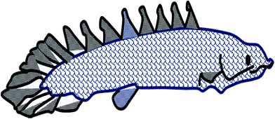
Recently, C. Ortiz et al. highlighted the great potential of a structure based on the structure–property function relationship of the dermal scales (Fig. 17) of armoured fish for the design of human body armour.230 W. Yang et al. critically investigated the scales of various fish (Atractosteus spatula, Arapaima gigas, Polypterus senegalus, Morone saxatilis, Cyprinius carpio) and the osteoderms from armadillos, alligators and leatherback turtles to gain an innate knowledge of flexible dermal armours.231 Y. Jia et al. investigated the thermal mechanical stress distribution and equivalent coefficient of the thermal expansion of the staggered arrangements of mineral platelets wrapped by the soft body matrix. They utilized two analytical models, namely the stress model and displacement model, and demonstrated their potential to provide benchmarks to the optimum design of micro/nanostructures for bioinspired materials exposed to temperature fluctuation and applied loadings.232,233
1.8 Common mechanics problem and comparison of armour materials
It has been observed that the perforation of target materials depends on the combination of more than one mechanism, such as the material properties, impact velocity, projectile tip shape, target support position and the relative dimensions of the target and projectile. There are several common features associated with the impact of a projectile with armour materials, such as:(1) When a projectile strikes an armour material, it imposes an intense, point-load on the body armour system (BAS).
(2) Due to the impact of the projectile, a medium-to-high-velocity impact event develops stress waves (or, under high enough impact pressures, even shock waves) in the armour material, which can be can be reflected from internal surfaces, leading to severe secondary effects, such as behind armour blunt trauma (BABT).
(3) The impact force is considered to be a non-uniform function of time but possesses a finite amount of input energy.
(4) The impact phenomenon ensues a shorter duration time (20 μs) for high energy projectiles.
(5) The impact of the projectile causes a localized deformation failure due to the development of high deformation strain.
(6) It has been observed that the response of the armour materials depends on their material properties, as well as on the impact conditions and strain rate.
(7) Materials experiencing the projectile impact may fail at the microstructural and nanostructural level, including the chemical phase and phase composition.
(8) The complete failure of the materials can occur in various modes, including adiabatic shear, bands, cracks, voids, plastic deformation and phase changes. It has been noticed that material failure is a kinetic process, which governs by the nucleation, growth and coalescence of the failure modes.
Table 13 and Fig. 18 show the advantages and disadvantages of various armour materials.
| Armour materials | Advantages | Disadvantages |
|---|---|---|
| Metallic armour (steel armour) | 1. Easy processing, 2. modification in a wide range of sizes and thicknesses, 3. offers protection against various kinds of projectile threats with the increasing thickness | 1. Steels are not actively involved in armour materials these days, 2. high density, which increase the weight of the material |
| Ceramic armour | 1. Low density, 2. light weight, 3. very compressive strength, 4. proved to be the best material for lower ballistic threats | 1. Catastrophic failure, 2. highly brittle, 3. provides protection against limited threats, 4. requires an additional backing plate, 5. defects during the process are the major challenges, 6. wearability is the biggest problem |
| Fibrous armour | 1. Low density, 2. light weight, 3. wearability, 4. a wide range of structure are possible, such as 2D and 3D structures, 5. multiple ply systems can be generated, 6. faster heat dissipation after the impact | 1. Environmental degradation, 2. localized melting of the fibre, 3. local comminution of the fibre, 4. reduction in ballistic efficacy in wet conditions |
| Integral and laminated armour | 1. Possibility of integrating various materials based on the ballistic threats, 2. provides high ballistic efficacy for the same weight as metal armours, 3. effective for high energy projectiles | 1. Delamination of the integrated materials, 2. matrix cracking and deboning, 3. intra- and inter-laminar separation |
| Biomimetic material system | 1. Higher impact property compared to its constituents, 2. multi-hit capability, 3. faster heat dissipation compared to other armour material, 4. offers a wide range of crack-arresting mechanisms | 1. Processing is a major challenge, 2. complete mimicking of natural structure is not yet achieved, 3. the developed materials are in the research phase only, 4. commercialization and large-scale production is a great challenge |
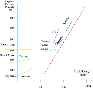 | ||
| Fig. 18 Comparison of armour materials for their projectile energy and areal density.234 | ||
1.9 Human vulnerability
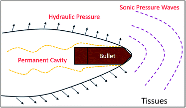
In recent years, it has been essential to understand vulnerability to explosive devices when designing armour protection for the human body. In this context, the work of Emil Theodor Kocher has been acknowledged as the first effort to develop a mechanism for understanding the wounding of the tissues by a bullet.235 Various studies demonstrated the involvement of three factors in the mechanism of tissues wounding, as shown in Fig. 19.19(a) A partial melting of the bullet on impact.
(b) The centrifugal force of the spinning bullet fired from the rifled barrel.
(c) Hydraulic pressure (high pressure region emanating from the bullet and expanding out radially behind it).
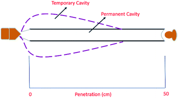
Harvey et al. illustrated that the disruption of tissue accompanied the change in the pressure due to the formation of a temporary cavity. Their experiments with suspended frogs' hearts in a water vat concluded that sonic pressure does not participate in the disruption of tissue and possesses no wounding effect.236 The mechanism of tissue penetration comprises two cavities: a temporary one and a permanent one. The temporary cavity is generated through the imparting of some or all of the kinetic energy of a bullet to the surrounding tissue, which then develops a greater wound cavity compared to the diameter of the bullet, as shown in Fig. 20. The temporary cavity returns to its equilibrium state when the projectile has passed through the tissue, while, the permanent cavity persists due to the inelastic compression of the damaged tissues. In contrast to the permanent cavity, the temporary cavity does not cause any damage to the tissue.27 In addition, a hollow-point projectile transmits more trauma to the human flesh due to the fragmentation of the bullet.19 The fragmentation of the bullet causes an extra dimensional expansion of its original diameter and multiple perforations of the tissue surrounding the bullet path. The minimum velocity required to penetrate the human skin is also tabulated in Table 14.
| Bullet | Speed (m s−1) | Penetration capability |
|---|---|---|
| 0.22′′ Lead air gun | 76.2 | Human skin |
| 0.177′′ Lead air gun | 91.4 | Human skin |
| Steel BB or 0.177′′ lead | 61 | Detached human iris of the human eye |
| Steel BB or 0.177′′ lead | 137.1 | Burst human eye |
| 158 gr 0.38′′ Special plain lead | — | Penetrates one side of a human skull |
| 158 gr 0.38′′ Special + P and 0.357′′ Magnum semi-jacketed bullets | — | Penetrates both side of a human skull |
2 Conclusions
In this article, we reviewed and discussed materials from metals to advanced functional systems and their development, with the various obstacles involved, to utilize them as efficient armour materials. Given the extent of the compositional variation and strategies involved in ancient and nacreous armour systems, we aimed to give an overview only of the principle elements on this topic. It is evident from the article that heavy metals can be utilized to counter recent advanced ammunition systems, but cannot meet the level of comfort required for mobility and reduced physiological stress. In this context, nature can offer a wide range of exoskeleton designs that bestow enhanced mechanical properties compared to their constituent materials. Biomimetic materials are those inspired by designs found in nature, and have attracted enormous attention in the recent years. We demonstrated the various evolution methodologies that have contributed to the development of unique structures in nacre systems, together with their failure mechanism. In contrast to the various review articles covering biomimetic evolution methodology, the toughening mechanisms and artificial materials to mimic the nacre, we focused on factors that have galvanized the research community to explore nature-inspired biomimic advanced functional materials.Acknowledgements
The authors acknowledge Dr Surendra Pal, Vice Chancellor, DIAT-DU and Prof Peter Hodgson, Deputy Vice Chancellor Research (DVCR), Deakin University, Australia for their continuous encouragement and support.References
- D. J. Papetti, Metallic Armour Materials, Ballistic Materials and Penetration Mechanics, ed. Roc C. Laible, Elsevier Scientific Publisher Company, New York, 1980, p. 146 Search PubMed.
- R. C. Laible and E. Barron, History of Armour, Ballistic Materials and Penetration Mechanics, ed. Roc C. Laible, Elsevier Scientific Publisher Company, New York, 1980, pp. 13–40 Search PubMed.
- Encyclopedia Britannica, Armor, 1974, vol. 2, p. 27 Search PubMed.
- N. Saxtorph, Warriors and Weapons of Early Times, Macmillan Co., New York, 1965 Search PubMed.
- V. Hurley, Arrows Against Steel: The History of the Bow, Mason/Charter, NY, 1975 Search PubMed.
- A. Snodgrass, Early Greek Armor and Weapons, Edinburgh University Press, Edinburgh, 1964 Search PubMed.
- R. F. Burton, The Book of the Sword, Barnes and Noble, New York, 1972 Search PubMed.
- C. H. Ashdown, British and Continental Arms and Armor, Dover Publications, New York, 1970 Search PubMed.
- H. R. Robinson, The Armor of Imperial Rome, Charles Scribner's Sons, New York, 1970 Search PubMed.
- S. V. Grancsay, Catalogue of Armor, Davis Press, Worchester, MA, 1961 Search PubMed.
- J. W. Anstee, Fragments of Roman "bronze" scale armour from Corbridge, Mus. J., 1953, 53, 200–202 CAS.
- B. Dean, Handbook of Arms and Armor, Metropolitan Museum of Art, New York, 1915 Search PubMed.
- R. Maddin, J. D. Muhly and T. S. Wheeler, How the Iron Age began, Sci. Am., 1977, 237(4), 122–131 CrossRef CAS.
- C. J. Ffoulkes, Armor and Weapons, E.P. Publishing Ltd., Yorkshire, England, 1973 Search PubMed.
- A. B. V. Norman and D. Pottinger, A History of War and Weapons 449 to 1660, Crowell, New York, 1966 Search PubMed.
- B. Grohskopf, The Treasure of Sutton Hoo Ship, Atheneum Press, New York, 1973 Search PubMed.
- C. J. Ffoulkes, Arms and Armor, British, Edgwore Middlesex, England, 1967 Search PubMed.
- S. Dunston, Flak Jacket, 20th Century Military Body Armour, Osprey Publishing, London, 1984, p. 3 Search PubMed.
- P. J. Hazell, Armour Materials, Theory and Design, CRC Press, Taylor and Francis Group, 2016 Search PubMed.
- J. B. Coates and J. C. Beyer, Wound Ballistics, Dept. of the Army, Washington, DC, 1962 Search PubMed.
- T. W. Baskin and J. B. Holcomb, Bombs, Mines, Blast, Fragmentation, and Thermobaric Mechanisms of Injury, Ballistic Trauma, A Practical Guide, Springer, 1997, pp. 45–66 Search PubMed.
- E. P. Hofmeister, M. Mazurek and J. Ingari, Injuries sustained to the upper extremity due to modern warfare and the evolution of care, J. Hand Surg., 2007, 32(8), 1141–1147 CrossRef PubMed.
- N. V. David, X.-L. Gao and J. Q. Zheng, Ballistic resistant body armor: contemporary and prospective materials and related protection mechanisms, Appl. Mech. Rev., 2009, 62(5), 050802–0508020 CrossRef.
- G. Cooper and P. Gotts, Ballistic Protection, Ballistic Trauma, A Practical Guide, Springer, 1997, p. 67 Search PubMed.
- A. Bhatnagar, Standards and specification for lightweight ballistic materials, Lightweight ballistic composite, Woodhead Publishing Limited, 2006, pp. 127–167 Search PubMed.
- B. J. Heard, Handbook of Firearms and Ballistics Examining and Interpreting Forensic Evidence Second Edition, John Wiley & Sons Ltd, 2008 Search PubMed.
- T. G. Montgomery, P. L. Grady and C. Tomasino, The Effects of Projectile Geometry on the Performance of Ballistic Fabrics, Text. Res. J., 1982, 52, 442 CrossRef.
- J. Diamond, Guns, Germs and Steel, The Fate of human Society, W. W. Norton & Company, New York London, 1997 Search PubMed.
- B. Dean, Helmets and body armor in modern warfare, Yale University Press London, 1920, p. 25 Search PubMed.
- J. M. Swank, The manufacturing of iron in all ages, The American Iron and Steel Association, 1892, p. 1 Search PubMed.
- W. Fairbairn, History, Properties & Process of Manufacture, Adam and Charles Black, Edinburgh, 1865, p. 4 Search PubMed.
- E. J. Brett, Arms and Armors, Sampson, Low, Marston and Co., Ltd., London, 1894 Search PubMed.
- M. L. Wilkins, Mechanics of penetration and perforation, Int. J. Eng. Sci., 1978, 16, 793–807 CrossRef.
- M. E. Backman and W. Goldsmith, The mechanics of penetration of projectiles into target, Int. J. Eng. Sci., 1978, 16, 1–99 CrossRef.
- J. A. Zukas, Introduction to Penetration Mechanism, High Velocity Impact Dynamics, John wiley & sons Inc, 1990, p. 309 Search PubMed.
- J. Awerbuch and S. R. Bodner, Analysis of the Mechanics of Perforation of Projectiles in Metallic Plates, Int. J. Solids Struct., 1974, 10, 671–684 CrossRef.
- W. Johnson, Impact strength of Materials, Edward Arnold, London, 1972 Search PubMed.
- H. Kolsky, Stress waves in solids, Dover, New York, 1963 Search PubMed.
- J. S. Rinehart, Stress Transients in Solids, Hyper Dynamics, Santa Fe NM, 1975 Search PubMed.
- J. A. Zukas, T. Nicholas, H. Swift, L. Greszczuk and D. R. Curran, Impact Dynamic, Wiley Inter science, New York, 1982 Search PubMed.
- D. E. Carlucci and S. S. Jacobson, Ballistics, Theory and Design of Guns and Ammunition, CRC Press, Taylor and Francis Group, 2008 Search PubMed.
- R. F. Recht, Containing ballistic fragments, in Engineering Solids under Pressure, ed. H. L. D. Pugh, The Institution of Mechanical Engineers, London, 1971, pp. 50–60 Search PubMed.
- R. F. Recht and T. W. Ipson, Ballistic perforation dynamics, J. Appl. Mech., 1963, 30(3), 384–390 CrossRef.
- R. F. Recht, Ballistic Perforation Dynamics of Armor-Piercing Projectiles, China Lake, CA, Naval Weapons Center, 1967 Search PubMed.
- M. J. Forrestal, V. K. Luk, Z. Rosenberg and N. S. Brar, Penetration of 7075-T651 Aluminum targets with ogival-nose rods, Int. J. Solids Struct., 1992, 29, 1729–1736 CrossRef.
- M. J. Forrestal, K. Okajima and V. K. Luk, Penetration of 6061-T651 Aluminum targets with rigid long rods, J. Appl. Mech., 1988, 55, 755–760 CrossRef.
- M. J. Forrestal, B. S. Altman, J. D. Cargile and S. J. Hanchak, An empirical equation for penetration depth of ogive-nose projectiles into concrete targets, Int. J. Impact Eng., 1994, 15(4), 395–405 CrossRef.
- J. deMarre, Perforation of iron and steel sheets with normal firing (trans.), Memorial de l’Artillerie de Marine 14, 1886 Search PubMed.
- C. Grabarek, Penetration of armor by steel and high density penetrators, Ballistic Research Laboratory BRL-MR-2134, 1971, AD 518394L Search PubMed.
- Project Thor technical report No. 47. The resistance of various metallic materials to perforation by steel fragments; empirical relationships for fragment residual velocity and residual weight, Ballistic Analysis Laboratory, The Johns Hopkins University, 1961 Search PubMed.
- T. W. Wright, A survey of penetration mechanics for long rods, Computational Aspects of Penetration Mechanics, ed. J. Chandra and J. E. Flaherty, Springer-Verlag, Berlin Heidelberg New York, 1983, pp. 85–106 Search PubMed.
- E. Medvedovski, Ballistic performance of armour ceramics: Influence of design and structure. Part 2, Ceram. Int., 2010, 36(7), 2117–2127 CrossRef CAS.
- R. L. Cook, Hard Faced Ceramic and Plastic Armor, Delaware: Goodyear Aerospace Corporation, 1970 Search PubMed.
- R. L. Cook, W. J. Hampshire, and R. V. Kolarik. Ballistic Armor System, Delaware: Goodyear Aerospace Corporation, 1979 Search PubMed.
- E. Medvedovski, Ballistic performance of armour ceramics: Influence of design and structure. Part 1, Ceram. Int., 2010, 36(7), 2103–2115 CrossRef CAS.
- W. A. Gooch Jr, Overview of the development of ceramic armor technology: Past, present and the future, Ceram. Eng. Sci. Proc., 2011, 32(5), 195–213 Search PubMed.
- W. Gooch, An Overview of Ceramic Armor Applications, International Conference on Advanced Ceramics and Glasses, PAC RIM IV, Maui, Hawaii, 4–8 November 2001 Search PubMed.
- W. Bruchey and E. Horwath, System Considerations Concerning the Development of High Efficiency Ceramic Armors, 17th Int. Sym. on Ballistics, Midrand, South Africa, March 1998 Search PubMed.
- W. Gooch and M. Burkins, Ballistic Development of U.S. High Density Tungsten Carbide Ceramics, Dymat 2000, Krakow, Poland, 23–29 September 2000 Search PubMed.
- W. Gooch, M. Burkins and R. Palicka, Development and Ballistic Testing of A Functionally Gradient Ceramic/Metal Applique, NATO Applied Vehicle Technology Panel, Loen, Norway, 7–11 May 2001 Search PubMed.
- W. Gooch, M. Burkins, L. Mills, J. Ogilvy, and A. Ricchiazzi, Cast Single Plate P900 Armor, US Pat., 5007326, April 16, 1991.
- M. J. Pawar, A. Patnaik, S. K. Biswas, U. Pandel, I. K. Bhat, S. Chatterjee, A. K. Mukhopadhyay, R. Banerjee and B. P. Babu, Comparison of ballistic performances of Al2O3 and AlN ceramics, Int. J. Impact Eng., 2016, 98, 42–51 CrossRef.
- D. Hallama, A. Heaton, B. James, P. Smith and J. Yeomans, The correlation of indentation behaviour with ballistic performance for sparkplasma sintered armour ceramics, J. Eur. Ceram. Soc., 2015, 35, 2243–2252 CrossRef.
- W. T. Lo, C. A. Jeng, J. L. Huang, H. H. Lu and D. F. Lii, Investigation of ballistic impact properties and fracture mechanisms of Ti3SiC2 ternary ceramics, J. Alloys Compd., 2008, 455, 413–419 CrossRef CAS.
- E. Medvedovski, Ballistic performance of armour ceramics: Influence of design and structure. Part 2, Ceram. Int., 2010, 36, 2117–2127 CrossRef CAS.
- E. Medvedovski, Ballistic performance of armour ceramics: Influence of design and structure. Part 1, Ceram. Int., 2010, 36, 2103–2115 CrossRef CAS.
- X. F. Zhang and Y. C. Li, On the comparison of the ballistic performance of 10% zirconia toughened alumina and 95% alumina ceramic target, Mater. Des., 2010, 31, 1945–1952 CrossRef CAS.
- Z. Zhou, G. Wua, L. Jiang, R. Li and Z. Xu, Analysis of morphology and microstructure of B4C/2024Al composites after 7.62 mm ballistic impact, Mater. Des., 2014, 63, 658–663 CrossRef CAS.
- S. G. Savio, K. Ramanjaneyulu, V. Madhu and T. Balakrishna Bhat, An experimental study on ballistic performance of boron carbide tiles, Int. J. Impact Eng., 2011, 38, 535–541 CrossRef.
- E. Ozsahin and S. Tolun, On the comparison of the ballistic response of coated aluminum plates, Mater. Des., 2010, 31, 3188–3193 CrossRef.
- S. N. Monteiron, L. H. L. Louro, A. V. Gomes, C. F. M. Chagas, A. B. Caldeira and É. P. Lima Jr, How effective is a convex Al2O3–Nb2O5 ceramic armor?, Ceram. Int., 2016, 42, 7844–7847 CrossRef.
- P. J. Hazell, G. J. Appleby-Thomas and S. Toone, Ballistic compaction of a confined ceramic powder by a non-deforming projectile: Experiments and simulation, Mater. Des., 2014, 56, 943–952 CrossRef CAS.
- M. L. Wilkins, Second Progress Report of Light Armor Program, Lawrence Radiation Laboratory, Livermore, CA, 1967 Search PubMed.
- M. L. Wilkins, C. A. Honodel, and D. Swale, An Approach to the Study of Light Armor, Lawrence Radiation Laboratory, Livermore, 1967 Search PubMed.
- M. L. Wilkins, Third Progress Report of Light Armor Program, Lawrence Radiation Laboratory, Livermore, 1968 Search PubMed.
- M. L. Wilkins, C. F. Cline and C. A. Honodel, Fourth Progress Report on Light Armor Program, Lawrence Radiation Laboratory, University of California, Livermore, 1969 Search PubMed.
- G. E. Hauver, P. H. Netherwood, R. F. Benck, W. A. Gooch, W. J. Perciballi, and M. S. Burkins, Variation of target resistance during long rod penetration into ceramics, Proceedings of the 13th International Symposium on Ballistics, Stockholm, Sweden, 1–3 June, 1992 Search PubMed.
- G. E. Hauver and A. Melani. Behavior during penetration by long rods', Proc. 2nd BRL Topical Symp. on ‘Experimental research and modeling support Aberdeen Proving Ground, MD, USA, US Army Ballistic Research Laboratory, May, 1988, pp. 149–160 Search PubMed.
- G. E. Hauver, P. H. Netherwood, R. F. Benck, W. A. Gooch, W. J. Perciballi and M. S. Burkins, Variation of target resistance during long-rod penetration into ceramics, Proc. 13th Int. Symp. On ‘Ballistics’, Sundyberg, National Defence Establishment, 1992, vol. 3, pp. 257–264 Search PubMed.
- Z. Rosenberg and Y. Yeshurun, Determination of the dynamic response of AD-85 alumina with in-material Manganin gauges, J. Appl. Phys., 1985, 58(8), 3077–3080 CrossRef CAS.
- Z. Rozenberg and Y. Yeshurun, The relation between ballistic efficiency and compressive strength of ceramic tiles, Int. J. Impact Eng., 1988, 7(3), 357–362 CrossRef.
- P. J. Hazell and M. J. Iremonger, Crack softening damage model for ceramic impact and its application within a hydrocode, J. Appl. Phys., 1997, 82(3), 1088–1092 CrossRef CAS.
- P. J. Hazell and M. J. Iremonger, The numerical analysis of dynamically loaded ceramic: A crack softening approach, Int. J. Numer. Meth. Eng., 2000, 48(7), 1037–1053 CrossRef.
- P. J. Hazell, S. E. Donoghue, C. J. Roberson, and P. L. Gotts, The penetration of armour piercing projectiles through reaction bonded ceramics. Advances in Ceramic Armor, A Collection of Papers Presented at the 29th International Conference on Advanced Ceramics and Composites, Cocoa Beach, FL, 23–28 January, 2005 Search PubMed.
- P. J. Hazell, T. Lawrence and C. Stennett, The defeat of shaped charge jets by explosively driven ceramic and glass plates, Int. J. Appl. Ceram. Technol., 2012, 9(2), 382–392 CrossRef CAS.
- T. J. Holmquist, and G. R. Johnson, A detailed computational analysis of interface defeat, dwell and penetration for a variety of ceramic targets, Proceedings of the 20th International Symposium on Ballistics, Orlando, FL, 23–27, September 2002 Search PubMed.
- T. J. Holmquist and G. R. Johnson, Response of silicon carbide to high velocity impact, J. Appl. Phys., 2002, 91(9), 5858–5866 CrossRef CAS.
- T. J. Holmquist and G. R. Johnson, Modeling prestressed ceramic and its effect on ballistic performance, Int. J. Impact Eng., 2005, 31(2), 113–127 CrossRef.
- T. J. Holmquist, C. E. Anderson Jr, and T. Behner, Design, analysis, and testing of an unconfined ceramic target to induce dwell, Proceedings of the 22nd International Symposium on Ballistics, 2005, vol. 2, pp. 860–868 Search PubMed.
- P. Lundberg, R. Renström, and L. Holmberg, An experimental investigation of interface defeat at extended interaction times, Proceedings of the 19th International Symposium on Ballistics, Interlaken, Switzerland, 7–11 May, 2001 Search PubMed.
- P. Lundberg and B. Lundberg, Transition between interface defeat and penetration for tungsten projectiles and four silicon carbide materials, Int. J. Impact Eng., 2005, 31(7), 781–792 CrossRef.
- P. C. den Reijer, Impact on ceramic faced armor, PhD dissertation, Delft University of Technology, The Netherlands, 1991.
- V. Madhu, K. Ramanjaneyulu, T. Balakrishn Bhata and N. K. Gupta, An experimental study of penetration resistance of ceramic armour subjected to projectile impact, Int. J. Impact Eng., 2005, 32, 337–350 CrossRef.
- A. L. Florence, Interaction of Projectiles and Composite Armor Part II, AMMRC CR 69–15, Stanford Research Institute, Palo Alto, August 1969 Search PubMed.
- J. D. Walker, and C. E. Anderson, An analytical model for ceramic-faced light armors, 16th International Symposium on Ballistics, San Francisco, CA, 23–28 September, 1996 Search PubMed.
- T. Antoun, O. Vorobiev, E. B. Herbold and S. Johnson, Mesoscale Modeling of the Dynamic Response of Armor Ceramics, Advances in Ceramic Armor VIII, ed. Jeffrey J. Swab, The American Chemical Society, 2013, p. 15 Search PubMed.
- E. P. Fahrenthold, A continuum damage model for fracture of brittle solids under dynamic loading, J. Appl. Mech., 1991, 58(4), 904–909 CrossRef CAS.
- D. R. Curran, L. Seaman, T. Cooper and D. A. Shockey, Micromechanical model for comminution and granular flow of brittle material under high strain rate application to penetration of ceramic targets, Int. J. Impact Eng., 1993, 13(1), 53–83 CrossRef.
- A. M. Rajendran, W. M. Ashmawi and M. A. Zikry, The modeling of the shock response of powdered ceramic materials, Comput. Mech., 2006, 38(1), 1–13 CrossRef.
- A. M. Rajendran and D. J. Grove, Modeling the shock response of silicon carbide, boron carbide and titanium diboride, Int. J. Impact Eng., 1996, 18(6), 611–631 CrossRef.
- M. B. Rubin and L. Lomov, A thermodynamically consistent large deformation elastic-viscoplastic model with directional tensile failure, Int. J. Solids Struct., 2003, 40(17), 4299–4318 CrossRef.
- E. Bar-on, M. B. Rubin and D. Z. Yankelevsky, Thermomechanical constitutive equations for the dynamic response of ceramics, Int. J. Solids Struct., 2003, 40(17), 4519–4548 CrossRef.
- D. Zhang, M. S. Wu and R. Feng, Micromechanical investigation of heterogeneous microplasticity in ceramics deformed under high confining stresses, Mech. Mater., 2005, 37(1), 95–112 CrossRef.
- D. Warner and J. Molinari, Micromechanical finite element modeling of compressive fracture in confined alumina ceramic, Acta Mater., 2006, 54(19), 5135–5145 CrossRef CAS.
- T. Sadowski and S. Samborski, Development of damage state in porous ceramics under compression, Comput. Mater. Sei., proceedings of the 16th International Workshop on Computational Mechanics of Materials - 1WCMM-16, 2008, vol. 43, pp. 75–81 Search PubMed.
- R. Kraft, J. Molinari, K. Ramesh and D. Warner, Computational micromechanics of dynamic compressive loading of a brittle polycrystalline material using a distribution of grain boundary properties, J. Mech. Phys. Solids, 2008, 56(8), 2618–2641 CrossRef CAS.
- P. D. Zavattieri and H. D. Espinosa, Grain level analysis of crack initiation and propagation in brittle materials, Acta Mater., 2001, 49(20), 4291–4311 CrossRef CAS.
- S. Berbenni, V. Favier and M. Berveiller, Micro-macro modeling of the effects of the grain size distribution on the plastic flow stress of heterogeneous materials, Comput. Mater. Sei., proceedings of the 15th International Workshop on Computational Mechanics of Materials, The 15th International Workshop on Computational Mechanics of Materials, 2007, vol. 39, pp. 96–105 Search PubMed.
- O. Vorobiev, Simple Common Plane contact algorithm, Int. J. Numer. Meth. Eng., 2012, 90, 243–268 CrossRef.
- G. R. Johnson and T. J. Holmequist, A computational constitutive model for brittle materials subjected to large strains, high rates, and high pressure, in Shock-Wave and High Strain Rate Phenomena in Materials, ed. M. A. Meyers, L. E. Murr and K. P. Staudhammer, New York, Marcel Dekker Inc, 1992, pp. 1075–1081 Search PubMed.
- G. R. Johnson and T. J. Holmquist, An improved computational constitutive model for brittle materials, AIP Conf. Proc., 1994, 309, 981 CrossRef CAS.
- G. R. Johnson, T. J. Holmquist and S. R. Beissel, Response of aluminum nitride (including a phase change) to large strains, high strain rates, and high pressures, J. Appl. Phys., 2003, 94(3), 1639–1646 CrossRef CAS.
- W. Carothers and J. W. Hill, Studies of polymerization and ring formation. xv. artificial fibers from synthetic linear condensation superpolymers, J. Am. Chem. Soc., 1932, 54, 1579 CrossRef CAS.
- L. I. Weiner and E. T. Vadala, Materials Evaluation Report No. 2718, US Army Natick R & D Command, MA, August 1950 Search PubMed.
- F. L. McCrackin, H. F. Schiefer, J. C. Smith and W. K. Stone, Stress-strain relationships in yarns subjected to rapid impact loading: 2. Breaking velocities, strain energies, and theory neglecting wave propagation, Text. Res. J., 1955, 25, 529 CrossRef.
- W. K. Stone, H. F. Schiefer and G. Fox, Stress-strain relationships in yarns subjected to rapid impact loading: 1. Equipment, testing procedure, and typical results, Text. Res. J., 1955, 25, 520 CrossRef.
- J. C. Smith, F. L. McCrackin and H. F. Schiefer, Stress strain relationships in yarns subjected to rapid impact loading: 3. Effect of wave propagation, Text. Res. J., 1955, 25, 701 CrossRef.
- R. C. Laible and H. M. Morgan, The viscoelastic behavior of oriented polyvinyl alcohol fibers at large strains, J. Polym. Sci., 1961, 54, 53 CrossRef CAS.
- W. C. Sheehan, R. E. Wellman, and T. B. Cole, Symp. On Polypropylene Fibers, Birmingham, AL, September 1969 Search PubMed.
- R. Laible, F. Figucia and J. Ferguson, The application of high-modulus fibers to ballistic protection, J. Macromol. Sci., Part A: Pure Appl.Chem., 1973, 7(1), 295 CrossRef CAS.
- S. L. Kwolek, Liquid Crystalline Polyamides, The chemist, 1980, 57(11), 9–12 CAS.
- X. Chen, Advanced Fibrous Composite Materials for Ballistic Protection, Woodhead Publishing, Elsvier ltd., Cambridge, 2016, pp. 18–27 Search PubMed.
- R. J. Morgan, C. O. Pruneda, N. Butler, F. M. Kong, L. E. Caley, and R. L. Moore, Proceedings of the 29th Natl. SAMPE Symposium, 1984, pp. 891–902 Search PubMed.
- R. J. Morgan, and R. E. Allred, Aramid Fiber Composites, Chapter in International Encyclopedia for Composites, ed. S. M. Lee, VCH Publishers, 1990, vol. 1, pp. 15–26 Search PubMed.
- R. J. Morgan, C. O. Pruneda and W. J. Steele, J. Polym. Sci., 1983, 21, 1757 CAS.
- D. Tanner, J. A. Fitzgerald and B. R. Phillips, The Kevlar Story an Advanced Materials Case Study, Angew. Chem., Int. Ed. Engl., 1989, 28, 5 CrossRef.
- H. H. Yang, Aromatic high-strength fibers, Wiley & Sons, USA, 1989 Search PubMed.
- H. H. Yang, Kevlar aramid fiber, Wiley & Sons, New York, 1993 Search PubMed.
- S. Rebouillat, Aramids: ‘disruptive’, open and continuous innovation, Advanced Fibrous Composite Materials for Ballistic Protection, Woodhead Publishing, Elsvier ltd., Cambridge, 2016, pp. 28–70 Search PubMed.
- J. W. Mead, K. E. Mead, I. Auerbach and R. H. Erlcksen, Accelerated Aging of Nylon 66 and Kevlar 29 in Elevated Temperature, Elevated Humidity, Smog, and Ozone, Ind. Eng. Chem. Prod. Res. Dev., 1982, 27, 158–163 CrossRef.
- H. A. Barness, Shear Thickening (“Dilatancy”) in Suspensions of Nonaggregating Solid Particles Dispersed in Newtonian Liquid, J. Rheol., 1989, 33(2), 329–366 CrossRef.
- R. L. Hoffman, Discontinuous and dilatants viscosity behavior in concentrated suspension I. Observation of flow instability, Trans. Soc. Rheol., 1972, 16, 155–173 CrossRef CAS.
- R. L. Hoffman, Interrelationship of particles structure and flow in concentrated suspension, Mater. Res. Bull., 1991, 16, 32–37 CrossRef CAS.
- R. L. Hoffman, Explanation for the cause of shear thickening in concentrated colloid suspension, J. Rheol., 1998, 42(1), 111–123 CrossRef CAS.
- N. J. Wegner and F. J. Brady, Shear thickening in colloidal dispersions, Phys. Today, 2009, 62, 27–32 CrossRef.
- Y. S. Lee and N. J. Wegner, Rheological properties and small angle neutron scattering of a shear thickening, nanoparticle, dispersion at high shear rate, Ind. Eng. Chem. Res., 2006, 45, 7015 CrossRef CAS.
- A. Srivastava, A. Majumdar and B. S. Butola, Imrpoving the impact resistance of textile structure by using shear thickening fluids: A review, Crit. Rev. Solid State Mater. Sci., 2012, 37, 115–129 CrossRef CAS.
- S. L. Young, E. D. Wetzel and N. J. Wagner, The ballistic impact characteristics of Kevlar woven fabrics impregnated with a colloidal shear thickening Fluid, J. Mater. Sci., 2003, 38(13), 2825–2833 CrossRef.
- M. J. Decker, C. H. Nam, N. J. Wagner and E. D. Wetzel, Stab resistance of shear thickening fluid (STF)-treated fabric, Compos. Sci. Technol., 2007, 67, 565–578 CrossRef CAS.
- E. D. Wetzel, Y. S. Lee, R. G. Egres, K. M. Kirkwood, J. E. Kirkwood and N. J. Wagner, The effect rheological parameters on the ballistic properties of shear thickening fluid 9STF) Kevlar composite, NUMIFORM, 2004, 1, 13–17 Search PubMed.
- Y. S. Lee, E. D. Wetzel, R. G. Egres and N. J. Wagner, Advanced body armour utilizing shear thickening fluids, 23rd Army science conference, Orlando, FL, 2002, vol. 1, pp. 2–5 Search PubMed.
- K. M. Kirkwood, J. E. Kirkwood, Y. S. Lee, R. G. Egres, N. J. Wagner and E. D. Wetzel, Text. Res. J., 2004, 74, 920–928 CrossRef CAS.
- D. P. Kalman, R. L. Merrill, N. J. Wagner and E. D. Wetzel, Effect of particle hardness on the penetration behavior of fabrics intercalated with dry particles and concentrated particle-fluid suspension, ACS Appl. Mater. Interfaces, 2009, 1(11), 2602–2612 CAS.
- J. Qin, G. Zhang, Z. Ma, J. Li, L. Zhou and X. Shi, Effects of ionic structures on shear thickening fluids composed of ionic liquids and silica nanoparticles, RSC Adv., 2016, 6, 81913 RSC.
- A. J. Pennings, A. Zwijnenburg and R. Lageveen, Longitudinal growth of polymer crystal from solution subjected to single shear flow, Kolloid Z. Z. Polym., 1973, 251, 500–501 CAS.
- A. J. Pennings and A. M. Keil, Fractionation of polymer crystallization from solution III. On the morphology of Fibrillar Polyethylene crystal growth in solution, Kolloid Z. Z. Polym., 1965, 205, 160–162 CAS.
- A. Zwijnenburg and A. J. Pennings, Longitudinal growth of polymer crystal from solution II. Polyethylene crystal in Poiseulle Flow, Colloid & Polymer Sci., 1975, 253, 452–461 CAS.
- A. Zwijnenburg and A. J. Pennings, Longitudinal growth of polymer crystal from solution III. Polyethylene crustal in Couette flow, Colloid & Polymer Sci., 1976, 254, 868–881 CAS.
- A. Zwijnenburg, P. F. van Hutten, A. J. Pennings and H. D. Chanzy, Longitudinal growth of polymer crystal from solution, V: structure and morphology of fibrillar polyethylene crystals, Colloid & Polymer Sci., 1978, 256, 729–740 CAS.
- T. Kanamoto, A. Tsuruta, K. Tanaka and M. Takeda, Superdrawing of ultrahigh molecular weight polyethylene. 1. Effect of technique on drawing of single crystal mats, Macromolecules, 1988, 21, 470–477 CrossRef CAS.
- P. Smith, P. J. Lemstra, J. P. L. Pijpers and A. M. Keil, Ultra-drawing of high molecular weight polyethylene cast from solutions III. Morphology and structure, Colloid Polym. Sci., 1981, 259, 1070–1080 CAS.
- S. Liu, J. Wang, Y. Wang and Y. Wang, Improving the ballistic performance of ultrahigh molecular weight polyethylene fiber reinforced composites using conch particles, Mater. Des., 2010, 31(4), 1711–1715 CrossRef CAS.
- L. H. Nguyen, S. Ryan, S. J. Cimpoeru, A. P. Mouritz and A. C. Orifici, The effect of target thickness on the ballistic performance of ultrahigh molecular weight polyethylene composite, Int. J. Impact Eng., 2015, 75, 174–183 CrossRef.
- D. Zhang, Y. Sun, L. Chen, S. Zhang and N. Pan, Influence of fabric structure and thickness on the ballistic impact behavior of Ultrahigh molecular weight polyethylene composite laminate, Mater. Des., 2014, 54, 315–322 CrossRef CAS.
- T. G. Zhang, S. S. Satapathy, L. R. Vargas-Gonzalez and S. M. Walsh, Ballistic impact response of Ultra-High-Molecular-Weight Polyethylene (UHMWPE), Compos. Struct., 2015, 133, 191–201 CrossRef.
- T. K. Ćwik, L. Iannucci, P. Curtis and D. Pope, Investigation of the ballistic performance of ultra high molecular weight polyethylene composite panels, Compos. Struct., 2016, 149, 197–212 CrossRef.
- X. Chen, Y. Zhou and G. Wells, Numerical and experimental investigations into ballistic performance of hybrid fabric panels, Composites, Part B, 2014, 58, 35–42 CrossRef CAS.
- S. P. Lin, J. L. Han, J. T. Yeh, F. C. Chang and K. H. Hsieh, Composites of UHMWPE fiber reinforced PU/epoxy grafted interpenetrating polymer networks, Eur. Polym. J., 2007, 43, 996–1008 CrossRef CAS.
- S. Ruan, P. Gao and T. X. Yu, Ultra-strong gel-spun UHMWPE fibers reinforced using multiwalled carbon nanotubes, Polymer, 2006, 47, 1604–1611 CrossRef CAS.
- Y. C. Wong, D. Ruan and M. L. Sesso, The influence of magnetic field on ballistic performance of aramid fibre and ultrahigh molecular weight polyethylene, Mater. Des., 2014, 64, 360–365 CrossRef CAS.
- Y. Peng, H. Wua, Q. Fang, J. Z. Liu and Z. M. Gong, Impact resistance of basalt aggregated UHP-SFRC/fabric composite panel against small caliber arm, Int. J. Impact Eng., 2016, 88, 201–213 CrossRef.
- M. R. O'Masta, V. S. Deshpande and H. N. G. Wadley, Mechanisms of projectile penetration in Dyneema encapsulated aluminum structures, Int. J. Impact Eng., 2014, 74, 16–35 CrossRef.
- N. Bhatnagar and N. Asija, Durability of high-performance ballistic composites, Lightweight Ballistic Composite, Elsevier publishing, 2016, p. 231284 Search PubMed.
- A. L. S. Alves, L. F. C. Nascimento and J. C. M. Suarez, Influence of weathering and gamma irradiation on the mechanical and ballistic behavior of UHMWPE composite armor, Polym. Test., 2005, 24, 104–113 CrossRef.
- P. A. Annis, Understanding and improving the durability of textiles, Woodhead Publishing Series in Textiles, number 132, 2012 Search PubMed.
- J. C. Smith, F. L. McCrackin, H. F. Schiefer, W. K. Stone and K. M. Towne, Stress-Strain Relationships in Yarns Subjected to Rapid Impact Loading Part IV: Transverse Impact Tests, Text. Res. J., 1956, 26(11), 821–828 CrossRef.
- D. Roylance, “Ballistics of Transversely Impacted Fibers, Text. Res. J., 1977, 47(10), 679–684 CrossRef.
- J. E. Field and Q. Sun, High-speed photographic study of impact on fibers and woven fabrics, in 19th Intl Congress on High-Speed Photography and Photonics, 1991, pp. 703–712 Search PubMed.
- A. F. Wilde, D. K. Roylance and J. P. M. Rogers, Photographic Investigation of High-Speed Missile Impact upon Nylon Fabric Part I_: Energy Absorption and Cone Radial Velocity in Fabric, Text. Res. J., 1973, 43(12), 753–761 CrossRef.
- B. J. Briscoe and F. Motamedi, The ballistic impact characteristics of aramid fabrics: The influence of interface friction, Wear, 1992, 158(1–2), 229–247 CrossRef.
- V. P. W. Shim, V. B. C. Tan and T. E. Tay, Modelling deformation and damage characteristics of woven fabric under small projectile impact, Int. J. Impact Eng., 1995, 16(4), 585–605 CrossRef.
- D. A. Shockey, D. C. Erlich, United States. Federal Aviation Administration, Office of Aviation Research, J. W. Simons, SRI International, and William J. Hughes Technical Center, Improved Barriers to Turbine Engine Fragments: Interim Report II, Office of Aviation Research, U.S. Federal Aviation Administration, 2002 Search PubMed.
- T. Chu, C. Minh and A. Imad, Analysis of local and global localizations on the failure phenomenon of 3D interlock woven fabrics under ballistic impact, Compos. Struct., 2017, 159, 267–277 CrossRef.
- Y. Wang, Y. Miao, L. Huang, D. Swenson, C. F. Yen, J. Yu and J. Q. Zheng, Effect of the inter-fiber friction on fiber damage propagation and ballistic limit of 2-D woven fabrics under a fully confined boundary condition, Int. J. Impact Eng., 2016, 97, 66–78 CrossRef.
- G. Nilakantan, Filament-level modeling of Kevlar KM2 yarns for ballistic impact studies, Compos. Struct., 2013, 104, 1–13 CrossRef.
- G. Nilakantan and J. W. Gillespie Jr, Ballistic impact modeling of woven fabrics considering yarn strength, friction, projectile impact location, and fabric boundary condition effects, Compos. Struct., 2012, 94, 3624–3634 CrossRef.
- S. Sockalingam, J. W. Gillespie Jr and M. Keefe, Dynamic modeling of Kevlar KM2 single fiber subjected to transverse impact, Int. J. Solids Struct., 2015, 67–68, 297–310 CrossRef.
- V. B. C. Tan, X. S. Zeng and V. P. W. Shim, Characterization and constitutive modeling of aramid fibers at high strain rates, Int. J. Impact Eng., 2008, 35, 1303–1313 CrossRef.
- K. Karthikeyan and B. P. Russell, Polyethylene ballistic laminates: Failure mechanics and interface effect, Mater. Des., 2014, 63, 115–125 CrossRef CAS.
- K. Luan, B. Sun and B. Gu, Ballistic impact damages of 3-D angle-interlock woven composites based on high strain rate constitutive equation of fiber tows, Int. J. Impact Eng., 2013, 57, 145–158 CrossRef.
- S. Mohan and S. Velu, Ballistic impact behaviour of unidirectional fibre reinforced composites, Int. J. Impact Eng., 2014, 63, 164–176 CrossRef.
- A. K. Bandaru, V. V. Chavan, S. Ahmad, R. Alagirusamy and N. Bhatnagar, Ballistic impact response of Kevlar® reinforced thermoplastic composite armors, Int. J. Impact Eng., 2016, 89, 1–13 CrossRef.
- E. M. Parsons, M. J. King and S. Socrate, Modeling yarn slip in woven fabric at the continuum level: Simulations of ballistic impact, J. Mech. Phys. Solids, 2013, 61, 265–292 CrossRef.
- C. Ha-Minh, F. Boussu, T. Kanit, D. Crépin and A. Imad, Analysis on failure mechanisms of an interlock woven fabric under ballistic impact, Eng. Failure Anal., 2011, 18, 2179–2187 CrossRef.
- B. A. Cheeseman and T. A. Bogetti, Ballistic impact into fabric and compliant composite laminates, Compos. Struct., 2003, 61, 161–173 CrossRef.
- J. C. Smith, F. L. McCrackin and H. F. Schiefer, Stress-Strain Relationships in Yarns Subjected to Rapid Impact Loading: 5. Wave Propagation In Long Textile Yarns Impacted Transversely, J. Res. Natl. Bur. Stand., 1958, 60(5), 517–534 CrossRef.
- J. C. Smith, J. M. Blandford and H. F. Schiefer, Stress-Strain Relationships in Yarns Subjected to Rapid Impact Loading Part VI: Velocities of Strain Waves Resulting from Impact, Text. Res. J., 1960, 30, 752 CrossRef.
- Y. Duan, M. Keefe, T. A. Bogetti and B. Powers, Finite element modeling of transverse impact on a ballistic fabric, Int. J. Mech. Sci., 2006, 48, 33–43 CrossRef.
- J. D. Walker and S. Chocron, Why impacted yarns break atlower speed than classical theory predicts, J. Appl. Mech., 2011, 78, 051021 CrossRef.
- S. Sockalingam, S. C. Chowdhury, J. W. Gillespie Jr and M. Keefe, Recent advances in modeling and experiments of Kevlar ballistic fibrils, fibers, yarns and flexible woven textile fabrics – a review, Text. Res. J., 2016, 1–27 Search PubMed.
- P. M. Cunniff, An analysis of the system effects of woven fabrics under ballistic impact, Text. Res. J., 1992, 62(9), 495–509 CrossRef CAS.
- Y. Duan, M. Keefe, T. A. Bogetti, B. A. Cheeseman and B. Powers, A numerical investigation of the influence of friction on energy absorption by a high-strength fabric subjected to ballistic impact, Int. J. Impact Eng., 2006, 32, 1299–1312 CrossRef.
- D. Roylance, A. Wilde and G. Tocci, Ballistic impact of textile structures, Text. Res. J., 1973, 43, 34–41 CrossRef.
- R. A. Prosser, The Penetration of Nylon Ballistic Panels by Fragment Simulating Projectiles, Part I: Linear Approximation to the Relationship Between the Square of the V50 or VC Striking Velocity and the Number of Layers of Cloth in the Ballistic Panel, U.S. Army Natick Research, Development and Engineering Center, Natick, MA, technical report NATICK/TR-85/027L, Aug. 1985 Search PubMed.
- K. Bilisik, Two-dimensional (2D) fabrics and three-dimensional (3D) preforms for ballistic and stabbing protection: A review, Text. Res. J. DOI:10.1177/0040517516669075.
- Y. Wang, X. Chen, R. Young, I. Kinloch and W. Garr, An experimental study of the effect of ply orientation on ballistic impact performance of multi-ply fabric panels, Text. Res. J. DOI:10.1177/0040517514566110.
- E. T. Thostenson, C. Li and T. W. Chou, Review, Nanocomposites in context, Compos. Sci. Technol., 2005, 65, 491–516 CrossRef CAS.
- P. M. Ajayan, Nanotubes from Carbon, Chem. Rev., 1999, 99, 1787–1799 CrossRef CAS PubMed.
- M. Terrones, Science and Technology of the Twenty-First Century: Synthesis, Properties, and Applications of Carbon Nanotubes, Annu. Rev. Mater. Res., 2003, 33, 419–501 CrossRef CAS.
- S. Lijima, Helical microtubules of graphitic carbon, Nature, 1990, 354, 56–58 Search PubMed.
- S. Lijima and T. Lchihashi, Single shell carbon nanotube of 1 nm diameter, Nature, 1993, 363, 603–604 CrossRef.
- D. S. Bethune, C. H. Kiang, M. S. de Vries, G. Gorman, R. Savoy and J. Vasquez, Cobalt-catalysed growth of carbon nanotubes with single-atomic-layer walls, Nature, 1993, 363, 605 CrossRef CAS.
- A. Oberlin, M. Endo and T. Koyama, Filamentous growth of carbon through benzene decomposition, J. Cryst. Growth, 1976, 32, 335–349 CrossRef CAS.
- K. Mylvaganam and L. C. Zhang, Energy absorption capacity of carbon nanotubes under ballistic impact, Appl. Phys. Lett., 2006, 89, 123127 CrossRef.
- K. Mylvaganam and L. C. Zhang, Ballistic resistance capacity of carbon nanotubes, Nanotechnology, 2007, 18, 475701–475704 CrossRef.
- S. L. Ruan, P. Gao, X. G. Yang and T. X. Yu, Toughening high performance ultrahigh molecular weight polyethylene using multiwalled carbon nanotubes, Polymer, 2003, 44, 5643–5654 CrossRef CAS.
- S. Ruan, P. Gao and T. X. Yu, Ultra-strong gel-spun UHMWPE fibers reinforced using multiwalled carbon nanotubes, Polymer, 2006, 47, 1604–1611 CrossRef CAS.
- T. Y. Kam, Mechanism Study of Carbon Nanotube Reinforced Ultra-High Molecular Weight Polyethylene Fibers, M.Phil. thesis, Hong Kong University of Science and Technology, 2008, p. 121.
- F. H. Gojny, M. Wichmann, B. Fiedler and K. Schulte, Influence of different carbon nanotubes on the mechanical properties of epoxy matrix composites: A comparative study, Compos. Sci. Technol., 2005, 6, 2300–2313 CrossRef.
- M. Rahman, M. Hosur, S. Zainuddin, U. Vaidya, A. Tauhid, A. Kumar, J. Trovillion and S. Jeelani, Effects of amino-functionalized MWCNTs on ballistic impact performance of E-glass/epoxy composites using a spherical projectile, Int. J. Impact Eng., 2013, 57, 108–118 CrossRef.
- M. A. Meyer and P.-Y. Chen, biological materials Science, biological materials, bioinspired materials and biomaterials, Cambridge University Press, 2014 Search PubMed.
- U. G. K. Wegst, H. Bai, E. Saiz, A. P. Tomsia and R. O. Ritchie, Bioinspired structural materials, Nat. Mater., 2015, 14, 23–36 CrossRef CAS PubMed.
- C. Ortiz and M. C. Boyce, Bioinspired Structural Materials, Science, 2008, 319, 153–154 CrossRef PubMed.
- G. Meyer, Rigid Biological Systems as Models for Synthetic Composites, Science, 2005, 310, 1144 CrossRef PubMed.
- Inspired by Biology: From Molecules to Materials to Machines, committee on Biomolecular Materials and Processes, National Research Counncil of the National Academies, The National Academies Press, Washington, DC, 2008 Search PubMed.
- J. Aizenberg and P. Fratzl, Biological and Biomimetic Materials, Adv. Mater., 2009, 21, 387–388 CrossRef CAS.
- D. Porter, J. Guan and F. Vollrath, Spider Silk: Super Material or Thin Fibre?, Adv. Mater., 2013, 25, 1275–1279 CrossRef CAS PubMed.
- F. Vollrath and D. Porter, Silks as ancient models for modern polymers, Polymer, 2009, 50, 5623 CrossRef CAS.
- I. Su and M. J. Buehler, Dynamic mechanics, The discovery of a hypersonic bandgap in spider silk could drive the design of bio-inspired and biocompatible dynamic materials, Nat. Mater., 2016, 1–2 Search PubMed.
- A. Rising and J. Johansson, Toward spinning artificial spider silk, Nat. Chem. Biol., 2015, 11, 309–315 CrossRef CAS PubMed.
- R. T. Abbott and S. P. Dance, Compendium of Seashells, Odyssey Publishing, 1998 Search PubMed.
- F. Nudelman, Nacre biomineralisation: a review on the mechanisms of crystal nucleation Seminar in shells & development biology, Semin. Cell Dev. Biol., 2015, 46, 2–10 CrossRef CAS PubMed.
- J. D. Currey and J. D. Taylor, The mechanical behaviour of some molluscan hard tissues, J. Zool. Res., 1974, 173, 395–406 CrossRef.
- P. E. Hare and P. H. Abelson, Amino Acid Composition of Some Calcified Proteins, Carnegie Inst Wash Year Book, 1965, pp. 223–34 Search PubMed.
- C. Gregoire, Topography of the organic components in mother-of-pearl, J. Biophys. Biochem. Cytol., 1957, 3, 797–808 CrossRef CAS PubMed.
- K. Wada, Mechanism of growth of nacre in bivalvia, Bull. Natl. Pearl Res. Lab., 1968, 13, 1561–1596 Search PubMed.
- N. Watabe, Studies on shell formation. xi. crystal-matrix relationships in the inner layers of mollusk shells, J. Ultrastruct. Res., 1965, 12, 351–370 CrossRef CAS PubMed.
- S. W. Wise, Microarchitecture and Mode of Formation of Nacre (Mother-of-Pearl) in Pelecypods, Gastropods, and Cephalopods, Eclogae Geol. Helv., 1970, 63, 775–797 Search PubMed.
- Q. L. Feng, F. Z. Cui, G. Pu, R. Z. Wang and H. D. Li, Crystal orientation, toughening mechanisms and a mimic of nacre, Mater. Sci. Eng., C, 2000, 11, 19–25 CrossRef.
- B. J. F. Bruet, J. Song, M. C. Boyce and C. Ortiz, Materials design principlesof ancient fish armour, Nat. Mater., 2008, 7, 748–756 CrossRef CAS PubMed.
- W. Yang, I. H. Chen, B. Gludovatz, E. A. Zimmermann, R. O. Ritchie and M. A. Meyers, Natural Flexible Dermal Armor, Adv. Mater., 2013, 25, 31–48 CrossRef CAS PubMed.
- Y. Jia, F.-Z. Xuan and F. Yang, Analysis of the effect of a compliant layer on indentation of an elastic material, J. Mech. Behav. Biomed. Mater., 2013, 25, 33–40 CrossRef CAS PubMed.
- Y.-F. Jia, F.-Z. Xuan and S.-T. Tu, A modified analysis for thermal–mechanical properties of staggered structure in biomimetic materials, J. Mech. Behav. Biomed. Mater., 2012, 16, 109–120 CrossRef PubMed.
- V. J. M. DiMaio, Gunshot Wounds, Practical Aspects of Firearms, ballistic, and Forensic Technique, CRC Press, 2016 Search PubMed.
- M. L. Fackler and P. J. Dougherty, Theodor Kocher and the scientific foundation of wound ballistics, Surg., Gynecol. Obstet., 1991, 172(2), 153–160 CAS.
- E. N. Harvey, I. M. Korr, G. Oster and J. H. McMillen, Secondary damage in wounding due to pressure changes accompanying the passage of high velocity missiles, Surgery, 1947, 21(2), 218–239 CAS.
| This journal is © The Royal Society of Chemistry 2016 |

