Rhenium(I) complexes with phenanthrolines bearing electron-withdrawing Cl and electron-donating CH3 substituents – synthesis, photophysical, thermal, and electrochemical properties with electroluminescence ability

Anna Świtlickaa, Tomasz Klemensa, Barbara Machura*a, Ewa Schab-Balcerzak*ab, Katarzyna Lababc, Mieczyslaw Lapkowskibc, Marzena Grucelab, Jacek Nycza, Marcin Szalaa and Magdalena Kaniad
aInstitute of Chemistry, University of Silesia, 9 Szkolna Str., 40-006 Katowice, Poland. E-mail: bmachura@poczta.onet.pl
bCentre of Polymer and Carbon Materials, Polish Academy of Sciences, 34 M. Curie-Sklodowska Str., 41-819 Zabrze, Poland. E-mail: ewa.schab-balcerzak@us.edu.pl
cSilesian University of Technology, Faculty of Chemistry, 9 Strzody Str., 44-100 Gliwice, Poland
dMass Spectrometry Group, Institute of Organic Chemistry, Polish Academy of Sciences, Kasprzaka 44/52, PO Box 58, 01-224 Warszawa 42, Poland

Received 26th September 2016 , Accepted 17th November 2016

First published on 18th November 2016


Abstract

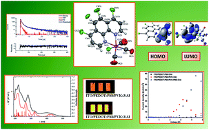
Five rhenium(I) tricarbonyl complexes incorporating 1,10-phenanthroline derivatives with electron-withdrawing Cl and electron-donating CH3 substituents were synthesized, and their photophysical, thermal, and electrochemical properties, with electroluminescence ability were examined. The melting temperature of these complexes was found to decrease from 391 to 281 °C upon adding methyl groups and decreasing the number of chlorine atoms. Compounds bearing methyl substituents could form amorphous molecular materials with glass transition temperatures in the range 118–127 °C. Cyclic voltammetry measurements demonstrated that the complexes are electrochemically active with low energy band gaps in the range 2.24–2.46 eV. All complexes are photoluminescent, form films in the solid state, and blend with poly(9-vinylcarbazole) (PVK) and PVK:(2-(4-tert-butylphenyl)-5-(4-biphenylyl)-1,3,4-oxadiazole) (PBD), emitting light with λem from 560 to 599 nm. They exhibited large Stokes shifts of up to 323 nm in solutions and up to 220 nm as film on a glass substrate. They were tested as guests in organic light-emitting diodes. As hosts, PVK and a binary matrix consisting of PVK with PBD were applied. The ability of the investigated complexes to emit light under an applied voltage was shown.


Introduction

The photochemistry and photophysics of coordination compounds have been the subject of intense research efforts for many years. The presence of a transition metal in molecules introduces new types of excited states, which differ in their localization within the molecule, energy, dynamics, and reactivity. Compared to organic molecules, the excited state density is much higher and several different excited states can occur within a narrow energy range. Consequently, excited states of different character (metal-to-ligand charge transfer (MLCT), ligand-to-ligand charge transfer (LLCT), σ-bond-to-ligand charge transfer (σ → π*), and intraligand (IL)) can interact with each other, leading to complex photobehavior.1 Having large spin–orbit coupling constants, transition metals substantially accelerate singlet → triplet intersystem crossing (ISC), producing the lowest triplet state on ultrafast time scales and yielding strong triplet-based photoluminescence of the order of microseconds in most cases.2

The continuing development of luminescent coordination compounds has largely been motivated by their possible use in catalysis,3 solar energy conversion,4 luminescence sensing,5 light-emitting diodes (LEDs),6 nonlinear optical materials,7 and molecular sensors.8

Since the first observation of electronically excited luminescence in [ReCl(CO)3(phen)], reported by Wrighton and Morse in 1974,9 particular attention has been devoted to rhenium(I) diimine tricarbonyls [Re(CO)3La(N–N)]n+ (La – axial ligand; n = 0 or 1). So far, a great number of investigations on the [Re(CO)3La(bipy)]n+ and [Re(CO)3La(phen)]n+ chromophores have appeared in the literature.10 The influence of structural variations of diimines, and the effect of the axial ligand on the photophysical and photochemical properties of rhenium(I) tricarbonyls have been investigated, both experimentally and computationally.11 For example, Rillema et al.12 examined the photobehavior of a series of Re(I) tricarbonyl complexes containing 2,6-dimethylphenylisocyanide and 5- and 6-derivatized phenanthroline ligands. Cardinaels13 and Pope14 demonstrated the effect of substitution patterns on the photoluminescent properties of rhenium(I) complexes incorporating substituted imidazo[4,5-f]-1,10-phenanthrolines.

Due to their remarkable photochemical and photophysical properties, diimine rhenium(I) tricarbonyls are still considered as excellent candidates for various applications in areas ranging from electronic and energy transfer to catalysis and medicinal chemistry. In this context, there is a need for the development of new luminescent rhenium(I) coordination compounds.

Herein, we report the synthesis, characterization, photophysical, thermal, and electrochemical properties of three novel rhenium(I) tricarbonyl complexes incorporating 1,10-phenanthroline derivatives: 2,5,9-trimethyl-4,7-dichloro-1,10-phenanthroline (2,5,9-(Me)3-4,7-Cl2phen), 2,9-dimethyl-4,7-dichloro-1,10-phenanthroline (2,9-(Me)2-4,7-Cl2phen), and 4,5,7-trichloro-1,10-phenanthroline (4,5,7-Cl3phen). For a better understanding of the effect of the number and location of chloro substituents in 1,10-phenanthroline, rhenium(I) tricarbonyls with 4,7-dichloro-1,10-phenanthroline (4,7-Cl2phen)2a,2b,9,15e and 5-chloro-1,10-phenanthroline (5-Clphen)2a,2b,9 were also included in the studies.

The luminescent properties of Re(I) complexes were studied in solution (CHCl3 and CH3CN) and solid state at room temperature, as well as in 4[thin space (1/6-em)]:[thin space (1/6-em)]1 EtOH–MeOH glass matrix at 77 K. To obtain a detailed insight into their electronic structures and spectroscopic properties, density functional theory (DFT) and time-dependent DFT (TD-DFT) calculations were performed.

Results and discussion

Synthesis and general characterization of Re(I) complexes

The complexes [ReCl(CO)3(2,5,9-(Me)3-4,7-Cl2phen)] (1), [ReCl(CO)3(2,9-(Me)2-4,7-Cl2phen)] (2), [ReCl(CO)3(4,5,7-Cl3phen)] (3), [ReCl(CO)3(4,7-Cl2phen)] (4), and [ReCl(CO)3(5-Clphen)]·CH3CN (5) were synthesized by heating equimolar mixtures of [Re(CO)5Cl] and the corresponding 1,10-phenanthroline derivative in acetonitrile.

The infrared spectra of 1–5 display three intense bands ν(CO) in the region 1876–2025 cm−1 with a typical pattern for complexes incorporating the fac-[Re(CO)3]+ moiety, two overlapping lower-energy bands (1937–1876 cm−1), and a sharp intense band at higher wavenumbers (2018–2025 cm−1). The presence of the phenanthroline ligand is shown in the IR spectra by medium intensity bands in the range 1617–1560 cm−1, corresponding to the ν(CN) and ν(C[double bond, length as m-dash]C) modes.

The 13C NMR spectra of 1–5 exhibit characteristic resonances around 198 and 189 ppm, corresponding to the carbonyl groups. Distinctive signals of the alkyl protons of the ligands 2,5,9-(Me)3-4,7-Cl2phen (in 1) and 2,9-(Me)2-4,7-Cl2phen (in 2) occur in the range 3.23–3.14 ppm, while the aromatic protons of the complexes of 1–5 were detected between 8.10 and 9.52 ppm (details are given in the Experimental part).

Molecular structures of rhenium(I) complexes

The crystallographic data for [ReCl(CO)3(2,5,9-(Me)3-4,7-Cl2phen)] (1), [ReCl(CO)3(4,5,7-Cl3phen)] (3), and [ReCl(CO)3(5-Clphen)]·CH3CN (5) are summarized in Table S1 (ESI). Perspective views showing the molecular structures of 1, 3, and 5 with the atom numbering are presented in Fig. 1. The crystal structure of 1 comprises two independent molecules per asymmetric unit, and only small variations in bond lengths and bond angles can be noticed between these molecules (Table S2). The rhenium ions of 1, 3, and 5 adopt a distorted octahedral coordination geometry with the largest deviations from the expected 90° bond angles being due to the geometrical constraints imposed by the five-member chelate ring of the phen ligand, with N–Re–N bite angles equal to 74.7(3) and 74.6(3)° for 1, 74.4(4)° for 3, and 75.28(14)° for 5. The three carbonyl groups are in a facial arrangement and the Re–CO bonds are nearly perpendicular to each other, with the angles OC–Re–CO falling in the range 83.8(5)–92.2(4)°. The Re–C (1.881(11)–1.938(12) Å) and Re–N (2.158(4)–2.213(7) Å) distances are unexceptional and they correlate well with values reported for the related tricarbonyl Re(I) complexes.15
image file: c6ra23935h-f1.tif
Fig. 1 A perspective view showing the asymmetric units of 1, 3, and 5 with the atom numbering. Displacement ellipsoids are drawn at 50% probability.

The structures 1, 3, and 5 are stabilized by short contacts, C–H⋯Cl, C–H⋯O, and C–H⋯N (Table S3), which can be considered as weak hydrogen bonds as well as by π–π type interactions. As demonstrated by the crystal packing analysis (Mercury 2.4 program16), the molecules in structures 1 and 3 are linked into dimers by π–π type interactions with centroid-to-centroid separations of 3.883(5) Å and 3.986(5) Å in 1 and 3.869(7) Å in 3 (Fig. S1). In the crystal lattice of 5, the molecules of [ReCl(CO)3(5-Clphen)] are extended into a 1D supramolecular network through two different π⋯π type interactions with centroid-to-centroid separations of 3.755(3) Å and 3.744(3) Å (Fig. S1).

DSC and TGA investigations

In the first heating scan of DSC measurements of all the rhenium(I) complexes, one endothermic peak corresponding to melting can be distinguished. The DSC thermograms of all complexes are presented in Fig. S16. Their melting temperature (Tm) was in the range 281–391 °C. The influence of the presence and number of methyl groups and number of chlorine atoms in the studied complexes on their thermal behavior is clearly pronounced. In the case of compounds without methyl groups bearing two and three chlorine atoms (3 and 4), melting, together with decomposition, was observed. Along with the extension of the number of chlorine atoms from one (5) to two (4) or three (3), a significant increase in Tm was seen (about 80 °C). Compounds with a methyl group (1 and 2), which were isolated as crystalline substances, were found to be able to convert into a glassy state by fast cooling of their melts. Thus, they could form amorphous materials, so-called molecular glasses, which are an interesting class of materials combining the advantages associated with small molecules with the potential to form glassy phases.17 When the isotropic liquid was cooled down and heated again, a glass transition in the range 118–127 °C was observed. On further heating, in the case of compound 2, peaks due to crystallization at 167 °C and melting at 283 °C appeared, contrary to compound 1, in which a DSC thermogram with only a Tg crystallization endotherm at 291 °C was registered. An increase in the number of methyl groups results in decreases in both Tm and Tg of about 20 and 9 °C, respectively. TGA revealed that the obtained complexes demonstrated high thermal stability. The 5% weight loss temperature (T5), which is usually considered as a criterion for determining the thermal stability, was in the range 295–395 °C (cf. Experimental section). Thus, a lack of thermal decomposition is observed below the melting temperature, except in compounds 3 and 4. These complexes melt with decomposition, as was mentioned above.

Electrochemical properties

The electrochemical properties of the Re(I) complexes were investigated using cyclic voltammetry (CV). From the onset of the oxidation and the first reduction peak, the ionization potential (IP) and electron affinity (EA), respectively, were estimated. Electrochemical data derived from CV measurements are summarized in Table 1, and a representative voltammogram is depicted in Fig. 2.
Table 1 Electrochemical data for Re(I) complexesa
Code Eox [V] Eox,onset [V] Ered1 [V] Ered2 [V] Ered3 [V] Ered,onset [V] IP [eV] EA [eV] Eg [eV]
a IP = −5.1 − Eox,onset, EA = −5.1 − Ered,onset, Eg = IP − EA.
1 1.06 0.95 −1.56 −1.73 −1.86 −1.47 −6.05 −3.63 2.42
2 1.06 0.95 −1.59 −2.19 −1.51 −6.05 −3.59 2.46
3 1.03 0.94 −1.38 −1.89 −2.06 −1.30 −6.04 −3.80 2.24
4 1.02 0.93 −1.49 −2.09 −1.42 −6.03 −3.68 2.35
5 0.99 0.91 −1.64 −2.12 −1.56 −6.01 −3.54 2.47


image file: c6ra23935h-f2.tif
Fig. 2 Cyclic voltammogram of 5 [scan rate 100 mV s−1, electrolyte 0.2 M Bu4NPF6 in acetonitrile].

The data from Table 1 indicate that the oxidation potentials were relatively insensitive to changes in the phenanthroline substituents, and a slight increasing tendency was observed in the order 5 < 4 < 3 < 2 < 1. The oxidation onsets of the Re(I) complexes are very close to each other. Based on the obtained data, a reduction process can be associated with the phenanthroline ligand, while the anodic wave can be associated with the Re(II/I) oxidation process. The second oxidation peak of rhenium Re(III/II) was not observed, probably due to the electrochemical window of acetonitrile. The oxidation process of the Re(I) complexes was irreversible, excluding the complexes with electron-donating group (CH3), that is, compounds 1 and 2. The first reduction process was quasi-reversible for all Re(I) complexes. To provide insight into the electroluminescent device fabrication of the investigated complexes, the IP/HOMO and the EA/LUMO were estimated. The EA decreases as the number of electron-withdrawing substituents increases, resulting in a decreased band gap in the order 5 > 4 > 3. Electron-donating –CH3 groups increase the EA of 1 and 2 compared to 4; however, the energy band gaps (Eg) obtained for complexes 1, 2, and 4 are very similar. The band-gap decreases in the order 5 > 2 > 1 > 4 > 3. The HOMO is determined mainly by the orbitals of the metal unit, while the LUMO is determined mainly by the orbitals of the ligand unit.15e It should be stressed that all Re(I) complexes exhibited a value of Eg useful for optoelectronic applications.

Absorption spectroscopy and DFT calculations

The UV-Vis spectra of rhenium(I) complexes have been studied in two solvents, which differ in polarity, (acetonitrile (ε = 37.5) and chloroform (ε = 4.8)), and in the solid state as films on glass substrates, and their spectral parameters are summarized in Table 2.
Table 2 Electronic spectral data for complexes 1–5
Complex Medium λ [nm] (103 ε [M−1 cm−1])
1 CH3CN 387.2 (6.16), 332.5 (9.10), 285.0 (28.57), 215.9 (55.60), 200.1 (53.08)
CHCl3 404.6 (2.98), 339.6 (3.92), 282.2 (17.80), 246.2 (18.88)
Film 396
2 CH3CN 382.1 (5.66), 330.3 (7.15), 270.7 (38.85), 231.4 (42.39), 215.6 (66.61), 196.1 (53.04)
CHCl3 373.8 (3.68), 272.8 (24.72)
Film 364
3 CH3CN 393.1 (8.85), 313.7 (12.5), 274.9 (43.77), 229.1 (46.99), 214.9 (64.11), 197.5 (55.48)
CHCl3 408.9 (4.48), 313.9 (6.8), 277.8 (28.04)
Film 405
4 CH3CN 380.4 (6.30), 268.3 (47.30), 212.8 (63.24)
CHCl3 399.9 (4.60), 270.9 (36.92)
Film 393
5 CH3CN 378.8 (6.05), 290.5 (19.72), 269.4 (40.40), 218.0 (48.16), 200.3 (63.46)
CHCl3 393.9 (3.32), 268.0 (37.24), 240.3 (37.04)
Film 385


With reference to previous spectroscopic studies for diimine rhenium(I) tricarbonyls, the intense absorptions at high energy (200–320 nm) are predominately attributable to intraligand (IL) transitions of the diimine moieties, while the moderately intense lowest energy absorption band is typically from the spin-allowed metal dπ(Re) to ligand image file: c6ra23935h-t1.tif charge transfer.

As can be expected, the position and intensity of the lowest energy absorption of 1–5 is solvent dependent, shifting to higher energy in more polar media by 14 nm for 1, 10 nm for 2, 16 nm for 3, 16 nm for 4, and 15 nm for 5, and the MLCT band is sensitive to the number and nature of substituents in the 1,10-phenanthroline ring. The extent of the red shift was in the order 3 > 4 > 5, with an increasing number of chloro substituents, which draw electron density from the phenanthroline ring.

To obtain a deeper understanding of the nature of excited states involved in absorption processes, time-dependent DFT (TDDFT) calculations at the B3LYP/def2-TZVPD level were performed for 1–5. The calculated and measured absorption spectra in acetonitrile solution are graphically compared in Fig. 3. It is observed that the main spectral features of 1–5 are predicted to a good accuracy, both in position and relative intensities, by the TDDFT calculations. Also, the structural parameters of the optimized structures of 1, 3, and 5 coincide well with the experimental bond lengths and angles (see Table S2). The calculated absorption energies associated with their oscillator strengths, their main contributions, and their assignments to the experimental results of 1–5 are given in Tables S4–S8 (see ESI). Fig. 4 presents the molecular orbital energy level graph for the examined rhenium(I) complexes, and the selected molecular orbitals of 1–5 are shown in Fig. S4 and characterized in Tables S9–S13.


image file: c6ra23935h-f3.tif
Fig. 3 Experimental (black) and calculated (red) electronic absorption spectra of 1–5 in CH3CN solution.

image file: c6ra23935h-f4.tif
Fig. 4 Molecular orbital energy level graph of 1–5 at the DFT/B3LYP/def2-TZVPD level.

As can be seen from Fig. 4, the LUMO energy decreases as the number of chloro substituents increases, resulting in a decreased band gap in the order 5 > 4 > 3, which then leads to an increase in the λmax of MLCT absorption (Table 2). On the other hand, electron-releasing –CH3 groups increase the LUMO energy of 1 and 2 compared to 4, which leads to an increased HOMO–LUMO band gap. The DFT/B3LYP/def2-TZVPD calculations showed a negligible effect of the third methyl group on the energy of the HOMO and LUMO orbitals of 1 in relation to 2; the HOMO–LUMO band gap is the same for 1 and 2.

The HOMO and HOMO−1 levels of 1–5 are very close in energy, and these orbitals are predominately constituted by 5dyz and 5dxz rhenium orbitals in a bonding relation to the carbonyl π* orbitals and an antibonding arrangement with chlorine occupied p orbitals. The HOMO−2 orbitals of 1–5 contain significant 5dxy rhenium (45–60%) character, along with ∼30% contributions from the CO component, and they are about ∼0.5 eV lower in energy in relation to the highest occupied molecular orbital. The LUMO and LUMO+1 levels are predominately centered on the phenanthroline ligand and particularly the π* antibonding orbital. These results are consistent with previously published studies on Re-phen carbonyl complexes.1a,18

According to TDDFT calculations, the lowest energy absorption of 1–5 arises from one-electron excitations H−1 → L, H → L+1, and H−1 → L+1, assigned as metal-ligand-to-ligand charge transfer transitions (MLLCT). With an increasing number of chloro substituents, the calculated low-energy absorption shift to lower energy is in the order 5 > 4 > 3. On the contrary, electron-donating groups lead to blue shifts of the H−1 → L excitations for 1 and 2 in relation to 4. For complexes 1–3, transitions of MLLCT character (H−2 → L+1) were also calculated to contribute to the higher energy absorption bands, at 333 nm for 1, 327 nm for 2, and 314 nm for 3. Generally, however, the intense bands in the high energy region are largely attributed to intraligand transitions (IL) and ligand–ligand charge transfer (LLCT).

Emission spectroscopy

The luminescence properties of complexes 1–5 were investigated in solution (CHCl3 and CH3CN) and solid state at room temperature as well as in 4[thin space (1/6-em)]:[thin space (1/6-em)]1 EtOH–MeOH glass matrix at 77 K. A summary of the photophysical data for 1–5 is gathered in Table 3.
Table 3 Summary of photoluminescent properties of the complexes 1–5
Complex Medium λex (nm) λem (nm) Stokes shift (cm−1) τ, ns (weight) χ2 Φ (%)
a (4 : 1 v/v).
1 CHCl3 408 640 8885 42.80 1.054 0.69
CH3CN 400 665 9962 15.38 1.114 0.14
Solid state 449 594; 716 5437, 8305 130.64 (37.39%), 386.69 (62.61%), 2.34 (29.87%), 41.84 (14.69%), 237.03 (55.43%) 1.179, 0.975 0.85
EtOH–MeOHa (77 K) 402 540 6357 7070 (53.88%), 25[thin space (1/6-em)]360 (46.12%) 1.030
Film 390 599 8558
Blend with PVK 330 386; 566    
Blend with PVK:PBD 330 384; 566
2 CHCl3 374 640 11[thin space (1/6-em)]113 39.72 1.124 0.58
CH3CN 375 665 11[thin space (1/6-em)]629 13.50 1.129 0.48
Solid state 473 618 4960 113.05 1.202 3.46
EtOH–MeOHa (77 K) 385 543 7558 1970 (12.80%), 6660 (59.94%), 16[thin space (1/6-em)]380 (27.26%) 1.097
Film 390 586 10[thin space (1/6-em)]407
Blend with PVK 330 387; 582  
Blend with PVK:PBD 330 386; 560  
3 CHCl3 408 680 9804 38.58 (76.48%), 141.89 (23.54%) 1.145 0.57
CH3CN 390 716 11[thin space (1/6-em)]675 14.14 (78.38%), 57.25 (21.62%) 0.974 0.50
Solid state 490 643 4856 119.09 1.133 4.11
EtOH–MeOHa (77 K) 373 569 9235 2590 (44.22%), 8720 (41.00%), 62[thin space (1/6-em)]190 (14.78%) 1.151
Film 390 610 8298
Blend with PVK 330 378; 589
Blend with PVK:PBD 330 378; 589
4 CHCl3 400 651 9639 69.53 1.198 0.89
CH3CN 380 690 11[thin space (1/6-em)]823 24.47 1.063 0.46
Solid state 442 591 5704 120.00 (11.30%), 459.99 (88.70%) 1.013 7.32
EtOH–MeOHa (77 K) 360 567 10[thin space (1/6-em)]141 1610 (14.95%), 5520 (75.89%), 17[thin space (1/6-em)]770 (9.15%) 1.097
Film 390 585 8351
Blend with PVK 330 384; 582
Blend with PVK:PBD 330 384; 577
5 CHCl3 397 634 9416 98.53 1.004 1.28
CH3CN 376 650 11[thin space (1/6-em)]211 44.81 1.123 0.48
Solid state 463 566 3930 525.33 (26.87%), 1259 (73.13%) 1.104 11.38
EtOH–MeOHa (77 K) 362 548 9376 3080 (23.54%), 7750 (69.24%), 38[thin space (1/6-em)]140 (7.22%) 1.178
Film 390 561 8552
Blend with PVK 330 385; 575
Blend with PVK:PBD 330 383; 565


Complexes 1–5 were found to be typical MLCT emitters. The irradiation of 1–5 in solution with wavelengths of 374–408 nm gave rise to emissions with maxima and Stokes' shifts in the ranges 634–716 nm and 8885–11[thin space (1/6-em)]823 cm−1, respectively. The emission bands are broad and structureless, and they show negative solvatochromism, reflected in blue-shifted emission with increasing solvent polarity. On going from CH3CN to CHCl3, the emissions of 1, 2, 3, 4, and 5 appeared at 25, 25, 36, 39, and 16 nm shorter wavelengths, which is attributed to a reduced (and reversed) molecular dipole in their MLCT excited states.7a,19 As can be seen from Table 3, complexes 1–5 also exhibit shortened lifetimes and decreasing emission quantum yields upon changing the solvent from CHCl3 to CH3CN. In similarity to the absorption behavior, the emission maximum wavelengths of 3, 4, and 5 show red-shifts with an increasing number of chloro substituents, in the order 3 > 4 > 5. On the other hand, the emissions of 1 and 2 appear in a lower-energy region compared to 4, but there is no marked difference in the fluorescence maximum wavelengths of 1 and 2.

Another characteristic feature of these complexes (except for 1) is the large hypsochromic shift of their emission maxima on going from a fluid environment to a rigid medium, 566–643 nm in the solid state and 540–569 nm upon cooling to low temperature (77 K), described as the rigidochromic effect. This is responsible for raising the energy of the emissive 3MLLCT due to the lack of solvent reorganization following excitation.8a,20

For 1, bimodal emission was observed, at 594 and 716 nm. A significant increase in lifetimes in the solid state and in a 77 K EtOH–MeOH matrix can be attributed to the intermolecular interactions in a more rigid environment, and decreased thermal deactivation.

The relatively long emission lifetimes, together with large absorption–emission shifts, indicate the phosphorescent nature of the emission.

The normalized emission spectra in solution, solid state as powder, and in alcohol glass at 77 K for representative compound 2 are shown in Fig. 5.


image file: c6ra23935h-f5.tif
Fig. 5 Normalized emission spectra in solution, solid state, and in alcohol glass at 77 K for compound 2.

The emission spectra of the remaining compounds are included in the ESI (Fig. S2).

Additionally, PL spectra of the complexes as thin films on glass substrates were recorded under λex = 390 nm. It was found that the λem of films was shifted to a higher energetic region with respect to the chloroform solution, as for complexes in the form of powder. In film, they exhibited large Stokes shifts of up to 220 nm, as in solution. The large Stokes shifts are desirable for emitting materials in OLEDs. A small Stokes shift can cause self-quenching and consequently decrease the emission intensity.21

The emission properties of 1–5 were also examined computationally at the DFT/UB3LYP/def2-TZVPD level. The energies of phosphorescence emissions of 1–5 were calculated from the energy difference between the ground singlet and the triplet state ΔET1–S0, as well as being computed using TD-DFT (Table 4, Fig. S5 and Table S14).

Table 4 Calculated phosphorescence emission energies of 1–5, compared to the experimental values recorded in acetonitrile solution
Compound DFT TD-DFT
ΔET1–S0 Character Major contribution (CI coefficient) E [eV] λcal [nm] Character λexp [nm] [eV]−1
1 1.97/629.4 3MLLCT L → H (0.649) 1.75 707.08 3MLLCT 665/1.86
2 1.98/626.2 3MLLCT L → H (0.663) 1.87 661.55 3MLLCT 665/1.86
3 1.90/652.5 3MLLCT L → H (0.662) 1.79 691.39 3MLLCT 716/1.73
4 1.97/629.4 3MLLCT L → H (0.666) 1.86 665.16 3MLLCT 690/1.79
5 2.09/593.2 3MLLCT L → H (0.655) 1.97 627.63 3MLLCT 650/1.90


As can be seen from Table 4, the calculated emission energies are in reasonably good agreement with the experimental emission band maxima of 1–5, indicating that the luminescence has characteristics of phosphorescence and occurs from the low-lying triplet state (T1). The nature of the transitions resulting in the emissions of 1–5 is 3MLLCT. Compared to the experimental data, the excitation energies calculated by the TD-DFT method lie closer than those of ΔET1–S0 for complexes 2–5, whereas ΔET1–S0 is more accurate than the excitation energies calculated by TDDFT for 1.

The next step of our research covers a study of the possible applications of the complexes as guest components in guest–host light-emitting diodes prepared by solution processing. Therefore, the photoluminescence ability of these complexes in the guest–host configuration as blends with poly(9-vinylcarbazole) (PVK) and in mixtures of PVK with (2-(4-tert-butylphenyl)-5-(4-biphenylyl)-1,3,4-oxadiazole) (PBD) (50[thin space (1/6-em)]:[thin space (1/6-em)]50 as weight%) were investigated. The content of the complexes in blends was 15 wt%. The layers of such compositions were used for light-emitting diodes (see the section on Electroluminescence). The emission spectra of the blends with complexes were recorded under excitation at 330 nm and 390 nm, corresponding to the λmax values of the matrices and the complexes, respectively. Under excitation at 330 nm, both matrices, that is, PVK and the mixture of PVK:PBD, exhibited the highest intensity emission (cf. Fig. S3 in ESI). All blends under λex = 390 nm did not show emission, except of blends with complex 5. In Fig. 6, the representative photoluminescence spectra of the matrices (PVK and PVK:PBD) and blend with dispersed compound 5 are compared.


image file: c6ra23935h-f6.tif
Fig. 6 (a) PL spectra of complex 5 as a thin film and blends under excitation at 330 nm and (b) absorption spectra of complex 5 in film and blend with PVK, together with emission spectra of PVK and PVK:PBD.

In the emission spectra of all complexes dispersed in matrices under excitation at 330 nm, two emission bands were observed. A band originating from the emission of both matrices was seen in a higher energy region around 400 nm, in relation to the band ascribed to the luminescence of the complexes from about 570–600 nm. In the guest–host diode configuration, two luminescence mechanisms are possible, that is, Förster energy transfer and charge trapping.22 The obtained results suggest that in PVK and PVK:PBD blends, Förster energy transfer from host to guest occurs, which is possible only if the emission spectrum of the matrix–host overlaps with the absorption spectrum of the guest molecule. As can be seen in Fig. 6b, the emission spectra of PVK and PVK:PBD overlap over a large range of the absorption spectra of the complexes. However, the emission of the matrices is still present in the PL spectra of the blends, indicating that the energy transfer is not complete. A higher intense emission was observed for complexes dispersed in a binary host matrix (PVK:PBD).

Electroluminescence

The electroluminescence (EL) of rhenium(I) complexes was investigated in simple guest–host light-emitting diodes, in which active layers were prepared by solution processing. In investigating the ability of the complexes for electroluminescence, two host matrices were selected, that is, PVK and a binary matrix PVK[thin space (1/6-em)]:[thin space (1/6-em)]PBD (50[thin space (1/6-em)]:[thin space (1/6-em)]50 wt%). PVK and PBD act as hole- and electron-transporting materials, respectively.

In these matrices, the complexes were dispersed with 15 wt% concentration. At the beginning of our research, devices with an emitting layer as a neat complex film with structure ITO/PEDOT:PSS:Re(I) complex/Al were prepared. Next the EL of the synthesized compounds was tested in devices with the configuration ITO/PEDOT:PSS/PVK:Re(I) complex/Al and ITO/PEDOT:PSS/PVK:PBD:Re(I) complex/Al.

For the prepared diodes, current density–voltage (JV) characteristics were registered. Fig. 7 presents an example of the JV characteristics, together with photos of diodes under an applied voltage, whereas the data obtained for all devices are summarized in Table 5. The thicknesses of the selected active layer and active layer surface were investigated by atomic force microscopy (AFM). The layers were characterized by similar thicknesses around 100–140 nm. The AFM images of the emitting layers show a uniform and flat surface with a surface root-mean-square roughness (RMS) in the range 1.8–4.9 nm.


image file: c6ra23935h-f7.tif
Fig. 7 Current density–voltage (JV) characteristics of the prepared devices based on complexes 3 and 5, and photos of diodes under an applied voltage.
Table 5 JV characteristic parameters of devices based on rhenium(I) phenanthrolines
Compound Active layer Von [V] Jmax [mA cm−2]
1 Film 3.0 0.6
PVK blend 2.8 18
PVK:PBD blend 2.6 19
2 Film
PVK blend 2.6 16
PVK:PBD blend 2.6 40
3 Film 3.5 2.6
PVK blend 2.1 35
PVK:PBD blend 2.6 76
4 Film 2.0 6
PVK blend 1.7 14
PVK:PBD blend 1.2 17
5 Film
PVK blend 2.2 65
PVK:PBD blend 1.6 46


In the case of diodes with the neat complex as emission layer, a low current density (J below 5 mA cm−2) was obtained and no light emission under the applied voltage was seen. The devices with an active layer consisting of complexes dispersed in matrices were characterized by low values of the turn-on voltage (Von) in the range 1.2–3.0 V, indicating efficient injection from the electrodes and transport of holes and electrons to the emission layers. The maximal achieved current density (Jmax) was in the range 14–76 mA cm−2. The highest Jmax values were found for devices based on compounds 3 and 5, used as emitters. The utilization of an additional electron-transporting compound (PBD) as a component of the emitting layer resulted in an improvement in the device performance. It should be emphasized that all fabricated diodes containing complexes in the blend emitted light under the applied voltage, which was more intense in the case of devices with a binary matrix. Thus, these complexes seem to be promising for applications, and further investigations covering measurements of electroluminescence parameters, together with diode architecture modification, are necessary and will be carried out.

Conclusions

To summarize, rhenium(I) phenanthroline complexes with electron-withdrawing Cl and electron-donating CH3 substituents were prepared and investigated, considering the effect of the number of chlorine atoms and methyl groups. It was found that the number and type of phenanthroline substituents impact the thermal behavior of the complexes. However, all of them are thermally stable enough for electronic applications. The complexes containing methyl substituents are molecular glasses, and an increase in the number of CH3 groups results in an increase in the Tg from 118 to 127 °C. A significant drop in the Tm with a reduction in the number of chlorine atoms from three/two to one was seen. The electrochemical results revealed that the ionization potential of the investigated complexes was independent of the substituents on the phenanthroline unit. They slightly differ in electron affinity values within the range 3.50–3.80 eV, which results in similar but low energy band gaps. The lowest Eg was exhibited by the compound bearing the greatest number of electron-withdrawing chlorine atoms. Compounds with electron-donating CH3 units undergo quasi-reversible oxidation, unlike the others without a methyl group. The complexes demonstrated photoluminescence both in solution and in the solid state, emitting light with λem in the ranges 574–610 nm and 566–601 nm in film and in blend, respectively. A slight bathochromic shift in λem from 574 to 610 nm accompanying an increase in the number of chlorine atoms is seen. In the case of compounds dispersed in PVK and PVK:PBD matrices, incomplete quenching of the emission of the matrix was observed. The application of a binary matrix yielded significantly more intensive photoluminescence of green light. The preliminary tests of utilization of the complexes in guest–host light-emitting diodes revealed their electroluminescence ability. Emission of light under an applied voltage was seen in all devices, which seems to be more intense for diodes based on the phenanthroline complex substituted with three Cl atoms, and for a device in which the complex is dispersed in a PVK:PBD matrix.

Experimental section

Materials

[Re(CO)5Cl] was commercially available (Sigma Aldrich) and was used without further purification. The 1,10-phenanthrolines have been prepared according to a procedure described in the literature.23–25

Poly(9-vinylcarbazole) (PVK) (Mn = 25[thin space (1/6-em)]000–50[thin space (1/6-em)]000) and 2-(4-tert-butylphenyl)-5-(4-biphenylyl)-1,3,4-oxadiazole (PBD) were purchased from Sigma Aldrich and used without additional purification. Poly(3,4-(ethylenedioxy)thiophene):poly-(styrenesulfonate) (PEDOT:PSS) (0.1–1.0 S cm−1) and substrates with pixelated ITO anodes were supplied by Ossila. All solvents for synthesis were of reagent grade and were used as received. For spectroscopy studies, HPLC grade solvents were used.

General synthesis route for rhenium(I) complexes (1–5)

[Re(CO)5Cl] (0.10 g, 0.27 mmol) and suitable 1,10-phenanthroline derivative ligands (0.27 mmol) were dissolved in acetonitrile (80 mL) and refluxed under argon for 6 hours. The resulting reaction solution was reduced in volume to 10 mL and allowed to cool to room temperature. The resulting yellow (2 and 4), orange (1 and 5), or dark red (3) solid was collected by filtration, washed with diethyl ether, and dried. X-ray quality crystals were obtained by slow recrystallization from acetonitrile.
[ReCl(CO)3(2,5,9-(Me)3-4,7-Cl2phen)] (1). Yield: 50%. IR (KBr, cm−1): 2018 (vs), 1900 (vs), and 1876 (vs) ν(C[triple bond, length as m-dash]O); 1609 (m) and 1578 (m) ν(C[double bond, length as m-dash]N) and ν(C[double bond, length as m-dash]C). 1H NMR (400 MHz, DMSO-d6): δ/ppm = δ 8.35 (d, J = 11.0 Hz, 2H), 8.18 (s, 1H), 3.20 (d, J = 4.1 Hz, 6H), 3.14 (s, 3H); 13C NMR (100 MHz, DMSO-d6): δ/ppm = 197.61, 189.43, 163.24, 150.69, 148.02, 145.28, 143.69, 142.10, 135.71, 129.51, 127.71, 127.36, 126.35, 124.77. MS: m/z 620.93 g mol−1 calcd for [M + Na]+ C18H12Cl3N2O3ReNa m/z 619.87 g mol−1. C18H12O3N2Cl3Re (596.86 g mol−1): calcd C, 36.22; H, 2.03; N, 4.69%; found: C, 36.84; H, 2.09; N, 4.71%. DSC Tm = 301 °C, Tg = 127 °C; TGA T5 = 341 °C.
[ReCl(CO)3(2,9-(Me)2-4,7-Cl2phen)] (2). Yield: 60%. IR (KBr, cm−1): 2020 (vs), 1912 (vs), and 1876 (vs) ν(C[triple bond, length as m-dash]O); 1617 (m) and 1560 (m) ν(C[double bond, length as m-dash]N) and ν(C[double bond, length as m-dash]C). 1H NMR (400 MHz, DMSO-d6): δ/ppm = 8.46 (s, 2H), 8.44 (s, 2H), 3.23 (s, 6H). 13C NMR (100 MHz, DMSO-d6): δ/ppm = 197.86, 189.76, 154.64, 147.34, 145.37, 129.23, 127.61, 125.38. MS: m/z 604.92 g mol−1; calcd for C17H10Cl3N2O3ReNa [M + Na]+ m/z 605.84 g mol−1. C17H10O3N2Cl3Re (582.84 g mol−1): calcd C, 35.03; H, 1.73; N, 4.81%; found: C, 34.95; H, 1.81; N. 4.92%; DSC Tm = 281 °C, Tg = 118 °C; TGA T5 = 295 °C.
[ReCl(CO)3(4,5,7-Cl3phen)] (3). Yield: 55%. IR (KBr, cm−1): 2025 (vs), 1911 (vs) and 1908 (vs) ν(C[triple bond, length as m-dash]O); 1604 (m) and 1560 (m) ν(C[double bond, length as m-dash]N) and ν(C[double bond, length as m-dash]C). 1H NMR (400 MHz, DMSO-d6): δ/ppm = 9.41 (dd, J = 12.9, 5.6 Hz, 2H), 8.59 (s, 1H), 8.33 (d, J = 5.5 Hz, 2H). 13C NMR (100 MHz, DMSO-d6): δ/ppm = 198.31, 190.65, 166.73, 155.66, 153.89, 150.04, 146.61, 144.04, 143.37, 143.28, 131.48, 131.37, 128.05, 127.63, 127.36, 122.76, 120.11, 113.48; MS: m/z 612.85 g mol−1 calcd for C15H5Cl4N2O3ReNa [M + Na]+ m/z 612.22 g mol−1. C15H5O3N2Cl4Re (589.23 g mol−1): calcd C, 30.57; H, 0.86; N, 4.75%; found: C, 30.50; H, 0.81; N, 4.48%; DSC Tm = 391 °C; TGA T5 = 382 °C.
[ReCl(CO)3(4,7-Cl2phen)] (4). Yield: 75%. IR (KBr, cm−1): 2024 (vs), 1902 (vs) and 1896 (vs) ν(C[triple bond, length as m-dash]O); 1616 (s) and 1561 (m) ν(C[double bond, length as m-dash]N) and ν(C[double bond, length as m-dash]C). 1H NMR (400 MHz, DMSO-d6): δ/ppm = 9.42 (d, J = 5.2 Hz, 2H), 8.59 (s, 2H), 8.35 (d, J = 5.3 Hz, 2H). 13C NMR (100 MHz, DMSO-d6): δ/ppm = 197.39, 189.23, 164.43, 148.55, 144.96, 127.52, 127.38, 124.02. MS: m/z 576.89 g mol−1; calcd for: C15H6Cl3N2O3ReNa [M + Na]+ m/z 577.79 g mol−1. C15H6O3N2Cl3Re (554.78 g mol−1): calcd C, 32.47; H, 1.09; N, 5.05%; found: C, 32.41; H, 1.08; N, 5.03%. DSC Tm = 390 °C; TGA T5 = 385 °C.
[ReCl(CO)3(5-Clphen)]˙CH3CN (5). Yield: 75%. IR (KBr, cm−1): 2020 (vs), 1937 (vs) and 1893 (vs) ν(C[triple bond, length as m-dash]O); 1615 (m) ν(C[double bond, length as m-dash]N) and ν(C[double bond, length as m-dash]C). 1H NMR (400 MHz, DMSO-d6): 1H NMR (400 MHz, DMSO) δ 9.52 (d, J = 4.8 Hz, 1H), 9.43 (d, J = 4.9 Hz, 1H), 9.10 (d, J = 3.9 Hz, 1H), 8.91 (d, J = 4.3 Hz, 1H), 8.64 (s, 1H), 8.24–8.21 (m, 1H), 8.13–8.10 (m, 1H). 13C NMR (125 MHz, DMSO-d6): δ/ppm = δ 198.04, 190.12, 154.85, 154.25, 147.21, 145.62, 139.23, 136.26, 130.89, 130.26, 128.96, 127.88, 127.66, 127.50. MS: m/z 484.94 g mol−1; calcd for C17H10Cl2N3O3ReNa [M + Na]+ m/z 483.76 g mol−1. C15H7O3N2Cl2Re (520.34 g mol−1): calcd C, 34.62; H, 1.35; N, 5.38%; found: C, 34.46; H, 1.38; N, 5.58%. DSC Tm = 311 °C; TGA T5 = 395 °C.

Film and blend preparation

Films and blends with 15 wt% concentration of Re(I) complex in PVK or PVK[thin space (1/6-em)]:[thin space (1/6-em)]PBD (50[thin space (1/6-em)]:[thin space (1/6-em)]50 in weight%) on a glass substrate were prepared by spin-coating from chloroform solution (10 mg mL−1). The homogenous solutions were spin cast (1000 rpm, 60 s).

Device preparation

Devices with three different configurations: ITO:PEDOT:PSS/Re(I) complex/Al, ITO:PEDOT:PSS/PVK:Re(I) complex/Al, and ITO:PEDOT:PSS/PVK:PBD:Re(I) complex/Al with 15 wt% complex content in blend were fabricated. Devices were prepared on OSSILA substrates with pixelated ITO anodes, and cleaned sequentially with detergent, deionized water, 10% NaOH solution, water, and isopropanol in an ultrasonic bath. Substrates were covered with PEDOT:PSS thin film (40 nm) by spin coating at 5000 rpm for 60 s and annealed for 30 min at 130 °C. The active layer was spin-coated on top of the PEDOT:PSS layer from chloroform solution (10 mg ml−1) at 1000 rpm for 60 s. Finally, an aluminum cathode was vacuum-deposited.

Crystal structure determination and refinement

The X-ray intensity data for 1, 3, 5, and 6 were collected on a Gemini A Ultra diffractometer equipped with an Atlas CCD detector and graphite monochromated MoKα radiation (α = 0.71073 Å) at room temperature. The unit cell determination and data integration were carried out using the CrysAlis package of Oxford Diffraction. Lorentz, polarization, and empirical absorption correction using spherical harmonics implemented in the SCALE3 ABSPACK scaling algorithm were applied.26 The structures were solved by the Patterson method using SHELXS97 and refined by full-matrix least-squares on F2 using SHELXL97.27 All the non-hydrogen atoms were refined anisotropically, and hydrogen atoms were placed in calculated positions refined using idealized geometries (riding model) and assigned fixed isotropic displacement parameters, d(C–H) = 0.93 Å, Uiso(H) = 1.2Ueq(C) (for aromatic); and d(C–H) = 0.96 Å, Uiso(H) = 1.5Ueq(C) (for methyl). The methyl groups were allowed to rotate about their local threefold axis. CCDC reference numbers: 1501825 (1), 1501826 (3), and 1501827 (5).

Computational details

The calculations have been performed using the GAUSSIAN-09 program package.28 The geometries of the singlet ground states (S0) and the lowest triplet states (T1) of 1–5 were fully optimized without any symmetry restrictions at the DFT level with the B3LYP hybrid exchange–correlation functional. The calculations were performed using the def2-TZVPD basis set for rhenium, the 6-31+G** basis set for chlorine, oxygen, and nitrogen, and 6-31G* for carbon and 6-31G for hydrogen atoms.29 The starting point for geometry optimization was taken from the X-ray structure, and all the subsequent calculations were performed based on the optimized geometries. Vibrational frequencies were calculated on the basis of the optimized geometry to verify that each of the geometries is a minimum on the potential energy surface. Furthermore, on the basis of the optimized ground and excited state geometries, the absorption and emission properties in acetonitrile (CH3CN) media were calculated by TD-DFT at the B3LYP hybrid functional level and with the polarized continuum model (PCM).30 The predicted bond lengths of 1, 3, 5, and 4 are compared with the experimental data in Table S2. The predicted bond lengths and angles for the ground state are within the range of error expected for DFT calculations of rhenium(I) complexes, and the general trends observed in the experimental data are well reproduced in the calculations, providing confidence in the reliability of the chosen method to reproduce the geometry of the studied complex (Table S2).

Acknowledgements

The research was co-financed by the National Research and Development Center (NCBiR) under Grant ORGANOMET No. PBS2/A5/40/2014. The calculations have been carried out at the Wroclaw Centre for Networking and Supercomputing (http://www.wcss.wroc.pl). K. Laba is a scholar supported by the “DoktoRIS—scholarship program for an innovative Silesia”, co-financed by the European Union within the European Social Fund.

References

  1. (a) A. Vlcek Jr and M. Busby, Coord. Chem. Rev., 2006, 250, 1755 CrossRef; (b) M. K. Kuimova, W. Z. Alsindi, A. J. Blake, E. S. Davies, D. J. Lampus, P. Matousek, J. McMaster, A. W. Parker, M. Towrie, X. Z. Sun, C. Wilson and M. W. George, Inorg. Chem., 2008, 47, 9857 CrossRef CAS PubMed; (c) A. W. Y. Cheung, L. T. L. Lo, C. C. Ko and S. M. Yiu, Inorg. Chem., 2011, 50, 4798 CrossRef CAS PubMed; (d) P. J. Wright, M. G. Affleck, S. Muzzioli, B. W. Skelton, P. Raiteri, D. S. Silvester, S. Stagni and M. Massi, Organometallics, 2013, 32, 3728 CrossRef CAS; (e) K. K. W. Lo, Acc. Chem. Res., 2015, 48, 2985 CrossRef CAS PubMed.
  2. (a) K. Kalyanasundaram, J. Chem. Soc., Faraday Trans. 2, 1986, 82, 2401 RSC; (b) A. J. Lees, Coord. Chem. Rev., 1998, 177, 3 CrossRef CAS; (c) C. Gourlaouen, J. Eng, M. Otsuka, E. Gindensperger and C. Daniel, J. Chem. Theory Comput., 2015, 11, 99 CrossRef CAS PubMed; (d) C. Daniel, Coord. Chem. Rev., 2015, 282–283, 19 CrossRef CAS; (e) J. Eng, C. Gourlaouen, E. Gindensperger and C. Daniel, Acc. Chem. Res., 2015, 48, 809 CrossRef CAS PubMed.
  3. (a) H. Takeda, K. Koike, H. Inoue and O. Ishitani, J. Am. Chem. Soc., 2008, 130, 2023 CrossRef CAS PubMed; (b) D. Wang, Q. L. Xu, S. Zhang, H. Y. Li, C. C. Wang, T. Y. Li, Y. M. Jing, W. Huang, Y. X. Zheng and G. Accorsi, Dalton Trans., 2013, 42, 2716 RSC; (c) E. Portenkirchner, D. Apaydin, G. Aufischer, M. Havlicek, M. White, M. C. Scharber and N. S. Sariciftci, ChemPhysChem, 2014, 15, 3634 CrossRef CAS PubMed; (d) E. Portenkirchner, S. Schlager, D. Apaydin, K. Oppelt, M. Himmelsbach, D. A. M. Egbe, H. Neugebauer, G. Knör, T. Yoshida and N. S. Sariciftci, Electrocatalysis, 2015, 6, 185 CrossRef CAS.
  4. (a) M. Busby, P. Matousek and M. Towrie Jr, J. Phys. Chem. A, 2005, 109, 3000 CrossRef CAS PubMed; (b) S. Sato, A. Sekine, Y. Ohashi, O. Ishitani, A. M. B. Rodriguez, A. Vlcek, T. Unno and K. Koike, Inorg. Chem., 2007, 46, 3531 CrossRef CAS PubMed; (c) A. Otavio, T. Patrocinio, M. K. Brennaman, T. J. Meyer and N. Y. M. Iha, J. Phys. Chem. A, 2010, 114, 12129 Search PubMed.
  5. (a) V. W. W. Yam, V. C. Y. Lau and K. K. Cheung, J. Chem. Soc., Chem. Commun., 1995, 259–261 RSC; (b) S. S. Sun and A. J. Lees, Coord. Chem. Rev., 2002, 230, 171 CrossRef CAS; (c) A. Otavio, T. Patrocinio and N. Y. M. Iha, Inorg. Chem., 2008, 47, 10851 CrossRef PubMed.
  6. (a) N. J. Lundin, P. J. Walsh, S. L. Howell, A. G. Blackman and K. C. Gordon, Chem.–Eur. J., 2008, 14, 11573 CrossRef CAS PubMed; (b) S. T. Lam, N. Zhu and V. W. W. Yam, Inorg. Chem., 2009, 48, 9664 CrossRef CAS PubMed; (c) X. Li, D. Zhang, G. Lu, G. Xiao, H. Chi, Y. Dong, Z. Zhang and Z. Hu, J. Photochem. Photobiol., A, 2012, 241, 1 CrossRef CAS; (d) W. K. Chu, C. C. Ko, K. C. Chan, S. M. Yiu, F. L. Wong, C. S. Lee and V. A. L. Roy, Chem. Mater., 2014, 26, 2544 CrossRef CAS; (e) G. W. Zhao, Y. X. Hu, H. J. Chi, Y. Dong, G. Y. Xiao, X. Li and D. Y. Zhang, Opt. Mater., 2015, 47, 173 CrossRef CAS; (f) X. Li, D. Zhang, W. Li, B. Chu, L. Han, J. Zhu, Z. Su, D. Bi, D. Wang, D. Yang and Y. Chen, Appl. Phys. Lett., 2008, 92, 083302 CrossRef.
  7. (a) S. S. Sun and A. J. Lees, Organometallics, 2002, 21, 39 CrossRef CAS; (b) S. S. Sun, D. T. Tran, O. S. Odongo and A. J. Lees, Inorg. Chem., 2002, 41, 132 CrossRef CAS PubMed.
  8. (a) K. K. W. Lo, M. W. Louie and K. Y. Zhang, Coord. Chem. Rev., 2010, 254, 2603 CrossRef CAS; (b) V. Fernandez-Moreira, F. L. Thorp-Greenwood and M. P. Coogan, Chem. Commun., 2010, 46, 186 RSC; (c) X. F. Wang, J. Lumin., 2013, 134, 508 CrossRef CAS.
  9. M. Wrighton and D. L. Morse, J. Am. Chem. Soc., 1974, 96, 998 CrossRef CAS.
  10. (a) A. S. Polo, M. K. Itokazu, K. M. Frin, A. O. de Toledo Patrocinio and N. Y. M. Iha, Coord. Chem. Rev., 2006, 250, 1669 CrossRef CAS; (b) J. E. Jones, B. M. Kariuki, B. D. Ward and S. J. A. Pope, Dalton Trans., 2011, 40, 3498 RSC; (c) R. Baková, M. Chergui, C. Daniel, A. Vlcek Jr and S. Zalis, Coord. Chem. Rev., 2011, 255, 975 CrossRef; (d) M. Kayanuma, E. Gindenspergera and C. Daniel, Dalton Trans., 2012, 41, 13191 RSC; (e) S. Sato and O. Ishitani, Coord. Chem. Rev., 2015, 282–283, 50 CrossRef CAS.
  11. (a) D. R. Striplin and G. A. Crosby, Coord. Chem. Rev., 2001, 211, 163 CrossRef CAS; (b) G. Velmurugan, B. K. Ramamoorthi and P. Venuvanalingam, Phys. Chem. Chem. Phys., 2014, 16, 21157 RSC; (c) P. Gómez-Iglesias, F. Guyon, A. Khatyr, G. Ulrich, M. Knorr, J. M. Martín-Alvarez, D. Miguela and F. Villafañe, Dalton Trans., 2015, 44, 17516 RSC.
  12. J. M. Villegas, S. R. Stoyanov, W. Huang and D. P. Rillema, Dalton Trans., 2005, 1042 RSC.
  13. T. Cardinaels, J. Ramaekers, P. Nockemann, K. Driesen, K. Van Hecke, L. Van Meervelt, S. Lei, S. De Feyter, D. Guillon, B. Donnio and K. Binnemans, Chem. Mater., 2008, 20, 1278 CrossRef CAS.
  14. R. O. Bonello, I. R. Morgan, B. R. Yeo, L. E. J. Jones, B. M. Kariuki, I. A. Fallis and S. J. A. Pope, J. Organomet. Chem., 2014, 749, 150 CrossRef CAS.
  15. (a) A. A. Marti, G. Mezei, L. Maldonado, G. Paralitici, R. G. Raptis and J. L. Colon, Eur. J. Inorg. Chem., 2005, 118 CrossRef CAS; (b) J. Qin, L. Hu, G. N. Li, X. S. Wang, Y. Xu, J. L. Zuo and X. Z. You, Organometallics, 2011, 30, 2173 CrossRef CAS; (c) C. O. Ng, S. W. Lai, H. Feng, S. M. Yiu and C. C. Ko, Dalton Trans., 2011, 40, 10020 RSC; (d) X. Liu, H. Xia, W. Gao, Q. Wu, X. Fan, Y. Mu and C. Ma, J. Mater. Chem., 2012, 22, 3485 RSC; (e) M. R. Gonçalves and K. P. M. Frin, Polyhedron, 2015, 97, 112 CrossRef.
  16. C. F. Macrae, I. J. Bruno, J. A. Chisholm, P. R. Edfinfton, P. McCabe, E. Pidcock, L. Rodriguez-Monge, R. Taylor, J. van de Streek and P. A. Wood, J. Appl. Crystallogr., 2008, 41, 466 CrossRef CAS.
  17. A. Plante, S. Palato, O. Lebel and A. Soldera, J. Mater. Chem. C, 2013, 1, 1037 RSC.
  18. X. Z. Yang, T. T. Zhang, J. Wei, J. F. Jia and H. S. Wu, Int. J. Quantum Chem., 2015, 115, 1467 CrossRef CAS.
  19. A. W. T. Choi, M. W. Louie, S. Po-Yam Li, H. W. Liu, B. T.-N. Chan, T. Chun-Ying Lam, A. Chun-Chi Lin, S. H. Cheng and K. K. W. Lo, Inorg. Chem., 2012, 51, 13289 CrossRef CAS PubMed.
  20. T. G. Kotch and A. J. Lees, Inorg. Chem., 1993, 32, 2570 CrossRef CAS.
  21. S. Ahn, Y. B. Cha, M. Kim, K. H. Ahn and Y. C. Kim, Synth. Met., 2015, 199, 8 CrossRef CAS.
  22. S. K. Mizoguchi, A. O. T. Patrocinio and N. Y. M. Iha, Synth. Met., 2009, 159, 2315–2317 CrossRef CAS; Q. Peng, N. Gao, W. Li, P. Chen, F. Li and Y. Ma, Appl. Phys. Lett., 2013, 102, 193304 CrossRef.
  23. G. I. Graf, D. Hastreiter, L. Everson da Silva, R. A. Rebelo, A. G. Montalban and A. McKillop, Tetrahedron, 2002, 58, 9095 CrossRef CAS.
  24. A. F. Larsen and T. Ulven, Org. Lett., 2011, 13, 3546 CrossRef CAS PubMed.
  25. A. Maroń, J. E. Nycz, B. Machura and J. G. Małecki, ChemistrySelect, 2016, 4, 798 CrossRef.
  26. CrysAlis RED, Version 1.171.35.11, Oxford Diffraction Ltd., 2011 Search PubMed.
  27. G. M. Sheldrick, Acta Crystallogr., Sect. A: Found. Crystallogr., 2008, 64, 112 CrossRef CAS PubMed.
  28. M. J. Frisch, G. W. Trucks, H. B. Schlegel, G. E. Scuseria, M. A. Robb, J. R. Cheeseman, G. Scalmani, V. Barone, B. Mennucci, G. A. Petersson, H. Nakatsuji, M. Caricato, X. Li, H. P. Hratchian, A. F. Izmaylov, J. Bloino, G. Zheng, J. L. Sonnenberg, M. Hada, M. Ehara, K. Toyota, R. Fukuda, J. Hasegawa, M. Ishida, T. Nakajima, Y. Honda, O. Kitao, H. Nakai, T. Vreven, J. A. Montgomery Jr, J. E. Peralta, F. Ogliaro, M. Bearpark, J. J. Heyd, E. Brothers, K. N. Kudin, V. N. Staroverov, R. Kobayashi, J. Norm, K. Raghavachari, A. Rendell, J. C. Burant, S. S. Iyengar, J. Tomasi, M. Cossi, N. Rega, J. M. Millam, M. Klene, J. E. Knox, J. B. Cross, V. Bakken, C. Adamo, J. Jaramillo, R. Gomperts, R. E. Stratmann, O. Yazyev, A. J. Austin, R. Cammi, C. Pomelli, J. W. Ochterski, R. L. Martin, K. Morokuma, V. G. Zakrzewski, G. A. Voth, P. Salvador, J. J. Dannenberg, S. Dapprich, A. D. Daniels, Ö. Farkas, J. B. Foresman, J. V. Ortiz, J. Cioslowski and D. J. Fox, Gaussian, Inc., Wallingford CT, 2009.
  29. (a) D. Andrae, U. Haeussermann, M. Dolg, H. Stoll and H. Preuss, Theor. Chim. Acta, 1990, 77, 123 CrossRef CAS; (b) M. Kaupp, P. V. Schleyer, H. Stoll and H. Preuss, J. Chem. Phys., 1991, 94, 1360 CrossRef CAS; (c) T. Leininger, A. Nicklass, W. Kuechle, H. Stoll, M. Dolg and A. Bergner, Chem. Phys. Lett., 1996, 255, 274 CrossRef CAS; (d) K. A. Peterson, D. Figgen, E. Goll, H. Stoll and M. Dolg, J. Chem. Phys., 2003, 119, 11113 CrossRef CAS; (e) B. Metz, H. Stoll and M. Dolg, J. Chem. Phys., 2000, 113, 2563 CrossRef CAS.
  30. (a) B. Mennucci and J. Tomasi, J. Chem. Phys., 1997, 106, 5151 CrossRef CAS; (b) M. T. Cances, B. Mennucci and J. Tomasi, J. Chem. Phys., 1997, 107, 3032 CrossRef; (c) M. Cossi, V. Barone, B. Mennucci and J. Tomasi, Chem. Phys. Lett., 1998, 286, 253 CrossRef CAS.

Footnote

Electronic supplementary information (ESI) available: Crystal data and structure refinement, short intra- and intermolecular contacts, comparison of experimental and theoretical bond lengths [Å] and angles [°], the energies and characters of the selected eletronic transitions with their assignment to the experimental absorption bands, percentage contributions of Re, CO, phen and Cl units in the selected occupied and unoccupied molecular orbitals in the ground state, 1H and 13C NMR spectra, DSC thermograms, excitation and emission spectra, emission spectra of PVK and PVK[thin space (1/6-em)]:[thin space (1/6-em)]PBD 1[thin space (1/6-em)]:[thin space (1/6-em)]1: films on glass. CCDC 1501825, 1501826 and 1501827. For ESI and crystallographic data in CIF or other electronic format see DOI: 10.1039/c6ra23935h

This journal is © The Royal Society of Chemistry 2016
Click here to see how this site uses Cookies. View our privacy policy here.