Doping structure and degradation mechanism of polypyrrole–Nafion® composite membrane for vanadium redox flow batteries

Qinglong Tana, Shanfu Lua, Yang Lva, Xin Xua, Jiangju Si*b and Yan Xianga
aBeijing Key Laboratory of Bio-inspired Energy Materials and Devices, School of Space and Environment, Beihang University, Beijing 100191, PR China
bSchool of Physics and Nuclear Energy Engineering, Beihang University, Beijing 100191, PR China. E-mail: sijiangju@buaa.edu.cn

Received 23rd September 2016 , Accepted 22nd October 2016

First published on 24th October 2016


Abstract

A HPPY–N212 composite membrane was prepared by the in situ polymerization of pyrrole on Nafion® 212 substrate membrane, followed by sulfuric acid treatment. The proton-acid doping structure endowed the HPPY–N212 membrane with enhanced conductivity as well as reduced vanadium ion permeability. These unique properties enabled vanadium redox flow battery (VRFB) fabricated with HPPY–N212 membrane to exhibit better coulombic, voltage and energy efficiency than that with N212 membrane under current densities of 60–150 mA cm−2. However, a gradual decay of voltage and energy efficiency occurred during the charge–discharge cycles. The efficiency decay resulted from the irreversible damage to PPY doping structure caused by the over-oxidation during charge–discharge cycles. These investigations help better understand the structure–performance relationships and open up exciting opportunities for the development of new high-performance membranes for VRFBs.
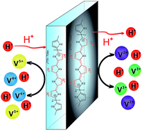

Vanadium redox flow batteries (VRFBs) have attracted worldwide attention in the past two decades due to their life-term stability, high efficiency and flexible design.1–5 As the key component of VRFBs, the isolated membrane acts as both a separator of active species and medium of ion transport. An ideal membrane should possess high ionic conductivity and low vanadium ion permeability.6,7 High selectivity to monovalent cations enables conducting polypyrrole (PPY) to transport proton and prevent vanadium ion.8 This unique property makes PPY a promising application in membrane material for VRFBs. Schwenzer9 and Wang10 prepared PPY–Nafion® composite membranes and confirmed that the PPY layer could decrease the permeability of VO2+ ion in the static state, but the conductivity decreased sharply with the increase in the thickness of PPY layer. The VRFBs fabricated with PPY–Nafion® composite membrane exhibited much lower energy efficiency even under the current density of 25 mA cm−2. Improving the conductivity of composite membranes while restricting the vanadium ion permeation is essential to increase the efficiency of VRFBs.

The conductivity of a composite membrane is significantly affected by the thickness and doping structure of PPY layers. The appropriate decrease in the thickness of PPY layer is necessary for enhanced conductivity. Moreover, acid treatment increases the ordering of PPY backbone and facilitates the proton transport.11 Here, to decrease the content of PPY in composite membrane, we used a pyrrole solution with much lower concentration and shortened the polymerization time. Furthermore, sulfuric acid treatment was conducted to improve the proton efficiency of composite membrane. The obtained composite membrane showed enhanced conductivity and reduced vanadium ion permeability because of the unique proton-acid doping structure of PPY. The VRFB fabricated with the composite membrane exhibited better coulombic, voltage and energy efficiency. However, a gradual decay of voltage and energy efficiency occurred during charge–discharge cycles. Further structure analysis showed that the energy efficiency decay resulted from the irreversible damage to PPY doping structure, which was caused by the overoxidation during the charge–discharge cycles. The results of this research helped to better understand of the relationship between the doping structure of PPY and performance of VRFB using a PPY–Nafion® composite membrane.

The in situ polymerization of pyrrole was carried out using ferric ions ion-exchanged Nafion®212 (N212) membrane as the oxidative agent. To decrease the content of PPY in the composite membrane, a 0.1 M pyrrole solution was selected and the polymerization time was 60 s. The ferric ions in the membrane were reduced to ferrous ions after the formation of a dark PPY layer; the obtained composite membrane was labeled as PPY–N212. The PPY–N212 membrane was then treated with a 0.5 M sulfuric acid solution and named as HPPY–N212 (Fig. S1a). The thicknesses of HPPY–N212 and N212 membranes were 50.9 ± 0.9 and 50.8 ± 0.5 μm, respectively, indicating that the thickness of the composite membrane had no significant change, and the introduced PPY layer was in the sub-micron range. To verify the structure of the composite membrane, attenuated total reflection Fourier transform infrared spectroscopy (ATR-FTIR) of N212, PPY–N212, and HPPY–N212 membranes was performed. Compared to N212 membrane, some new absorption peaks appeared in the composite PPY–N212 membrane (Fig. 1a). The absorption bands at 914, 1040, 1470, and 1540 cm−1 were assigned to the N–H, C–H in plane vibrations, C–N stretching, and C[double bond, length as m-dash]C ring stretching of PPY, respectively.12–14 These new characteristic absorption bands confirmed the formation of PPY layer. Furthermore, for PPY–N212 membrane, the asymmetric stretching vibration (νas) peak of SO3 shifted from 1056 cm−1 to 1040 cm−1, the possible reason was that the SO3 ions of N212, the only anions existing in the polymerization system, acted as the doping anions of the oxidized conjugated PPY chains (Fig. 1e). After the treatment with sulfuric acid, νas (SO3) was restored to 1056 cm−1, because sulfonic acid of N212 was released from the doping state, and the HSO4 or SO42− became the new counter anions as a result of ion exchange. Moreover, the peaks at 1540 cm−1 of C[double bond, length as m-dash]C ring in PPY had a red shift, indicating that the structure of C[double bond, length as m-dash]C bond of pyrrole rings changed during the treatment with sulfuric acid. During the acidification, proton-acid doping occurred, and the β-C was preferentially protonated.15 The change in the absorption peak of C[double bond, length as m-dash]C provided evidence that the doping structure of PPY transferred from oxidized conjugated chain doped with counter anions to proton-acid doping after the acidification (Fig. 1e).15 The proton-acid doping is vital to improve the short-range ordering of PPY backbone and conductivity of composite membrane owing to the efficient proton transport in the PPY conjugated chains.11


image file: c6ra23630h-f1.tif
Fig. 1 (a) FT-IR spectra of N212, PPY–N212 and HPPY–N212 membranes. (b) Raman spectra of PPY–N212 and HPPY–N212 membranes. (c) X-ray photoelectron spectra (XPS) of N1s and (d) C1s of PPY–N212 and HPPY–N212 membranes. (e) The change in doping structure after the treatment with sulfuric acid.

Raman spectra was performed on the PPY–N212 and HPPY–N212 membranes. As shown in Fig. 1b, the characteristic peaks appeared at 1600, 1370, 1260, 1098, 1060, 970, and 930 cm−1, further confirming the successful introduction of PPY layer. Furthermore, the area of peaks at 1098, and 930 cm−1 related to the dication structure is much larger than that of 1060 and 970 cm−1 related to the radical cation structure, suggesting that the dication structure dominated in the PPY layer.16–19 Additionally, a slightly enhanced intensity of the cation structure from 930 to 1098 cm−1 for HPPY–N212 membrane, manifesting that acidification resulted in the increase of the number of cation units derived from the protonation of PPY. The cation units of HPPY–N212 membranes are beneficial to improve the conductivity and hinder the vanadium ion permeation by Donnan exclusion.

Further, X-ray photoelectron spectroscopy (XPS) was used to characterize the N and C state in PPY–N212 and HPPY–N212 membranes. The presence of PPY in PPY–N212 membrane was evidenced by the appearance of N1s peak at the range 400–403 eV (Fig. 1c) and C1s peak at 284.7 eV (Fig. 1d). The peaks at the binding energies (BE) of about 399.6, 400.2, and 402.5 eV (Fig. S2) were attributed to quinonoid imine units ([double bond, length as m-dash]N– structure), pyrrolylium nitrogens (–NH– structure) and positively charged nitrogens ([double bond, length as m-dash]N+H– structure), respectively.20,21 The content of N in HPPY–N212 membrane was 4.48%. The higher BE of the C1s peak at 291.5 eV can be assigned to its π–π* shake-up satellites.18 For HPPY–N212 membrane after treatment with sulfuric acid, no obvious shift was observed in the BE of N1s, however, the C1s and its shake-up satellites showed smaller BE. These results affirmed that protonation mainly happened at the β-C in PPY. Notably, the intensity of π–π* shake-up satellites showed a remarkable increase, because of the shift of PPY structure from oxidized conjugated chain to proton-acid doping structure (Fig. 1e).

It was difficult to observe the morphology of HPPY–N212 membrane by common scanning electron microscopy (SEM) (Fig. S3), because the PPY layer in the composite membrane was very thin. Small-angle X-ray scattering (SAXS) is another important tool to identify the morphology of ionomers especial for Nafion® membrane.22–24 However, much attention has not paid to its application in the field of membranes for VRFBs. Herein, the morphology of HPPY–N212 membrane was investigated by SAXS. As shown in Fig. 2, the ionomer peak of N212 membrane appeared at 1.5 nm−1 and the corresponding size of hydrophilic clusters was 4.2 nm. The peak at 0.5 nm−1 was related to the crystalline structure of N212.22 After the introduction of PPY, no obvious shift in the peak related to crystallinity was observed, however, the ionomer peak of HPPY–N212 membrane shifted to a larger q (1.8 nm−1), indicating that the clusters became smaller (3.5 nm−1), and the hydrophilic channels became narrower. This is probably because the polymerization of pyrrole occurred not only on the surface, but also in the inner hydrophilic domains of N212 membrane, and the formed PPY layer blocked the channels of N212 membrane. This result is consistent with that obtained by Wang.10 The morphology investigation of HPPY–N212 membrane by SAXS was important. We confirmed the location of PPY in the composite membrane as well as the size of hydrophilic channels. This has a significant influence on the conductivity and vanadium ion permeability of composite membrane.


image file: c6ra23630h-f2.tif
Fig. 2 Small-angle X-ray scattering (SAXS) profile of N212 and HPPY–N212 membranes.

The conductivities of N212 and composite HPPY–N212 membrane were measured and the results were shown in Fig. 3a. Surprisingly, the enhanced conductivity was observed for HPPY–N212 membrane, consistent with the results obtained by Cheah.11 This result demonstrated that a slight decrease in the width of hydrophilic channels from 4.2 nm to 3.5 nm did not significantly affect on the proton transport in HPPY–N212 membrane. The excellent conductivity of the composite membrane was dependent on its structure. After the acidification, the protonation of PPY increased the quantity of proton in the composite membrane. Furthermore, as mentioned above, the acid treatment endowed the thin PPY layers with an ordered proton-acid doping structure, and the delocalized protons transported efficiently in the conjugated chains of PPY accompanied by the doping of counter anions.


image file: c6ra23630h-f3.tif
Fig. 3 (a) Proton conductivity of N212 and HPPY–N212 membranes and the ordered proton-acid doping structure of PPY. (b) The diffusion rate of VO2+ ions in N212 and HPPY–N212 membranes.

The permeability of VO2+ ions across the composite HPPY–N212 and N212 membranes was measured. Fig. 3b demonstrated the diffusion rate of VO2+ ions in N212 and HPPY–N212 membranes. The diffusion rate of VO2+ ions decreased substantially in HPPY–N212 membrane, highlighting that the introduction of PPY effectively hindered the transport of VO2+ ions across the membranes. Two mechanisms are involved in the obstruction VO2+ ions in the PPY layer: (1) size exclusion. As referred in the SAXS results, the PPY layer narrowed the hydrophilic channels of composite membrane, and increased the extra mass transfer resistance. (2) Donnan exclusion. Protonation of β-C in PPY made HPPY–N212 positively charged; the electrostatic repulsion decreased the diffusion rate of VO2+ ions across the membranes. The introduction of a thin PPY layer improved the conductivity while hindering the permeation. These results laid a foundation for the application of HPPY–N212 membrane in VRFBs.

To study the electrochemical performance of the composite membrane, HPPY–N212 membrane was used to assemble a VRFB single battery. Fig. 4 illustrated the charge and discharge profiles at a current density of 60 mA cm−2. Because HPPY–N212 membrane had a higher conductivity and lower vanadium ion permeability, the VRFB installed with HPPY–N212 membrane showed a lower charge platform (1.3 V) and higher discharge platform (1.5 V) compared to the VRFB with N212 membrane. Moreover, the VRFB fabricated with HPPY–N212 membrane exhibited better columbic efficiency (CE), voltage efficiency (VE) and energy efficiency (EE) under current densities of 60–150 mA cm−2, and the VE and EE had more significant increase in contrast to CE (Fig. 5a). These results highlight the contribution of thin PPY layers in enhancing the VRFB performance. Because PPY showed no obvious catalytic activity towards the V(IV)/V(V) redox pair (Fig. S4), the higher VE can be attributed to the improved conductivity of HPPY–N212 membrane, confirming that thin PPY layers accelerate the proton transport. To further investigate the chemical stability of the HPPY–N212 membrane, a VRFB assembled with the HPPY–N212 membrane was cycled at a current density of 90 mA cm−2 (Fig. 5b). In the whole 90 cycles, the VRFB with HPPY–N212 membrane showed a higher CE, VE and EE than those of N212 membrane, and the CE had no obvious decay. However, the EE and VE decayed synchronously at a larger rate than those of the VRFB with N212 membrane, indicating that the VE decay was the main reason for the decline of EE. After the cycling, the dark PPY layer exposed to electrolyte faded and turned yellow (Fig. S1b).


image file: c6ra23630h-f4.tif
Fig. 4 Charge–discharge voltage profiles of a VRFB employing HPPY–N212 and N212 membranes at 60 mA cm−2.

image file: c6ra23630h-f5.tif
Fig. 5 (a) Efficiency of a VRFB using HPPY–N212 and N212 membranes with current densities in the range 60–150 mA cm−2. (b) Cycling performance of a VRFB installed with a HPPY–N212 membrane at 90 mA cm−2.

To investigate the efficiency decay mechanism of the VRFB installed with HPPY–N212 membrane, XPS and FT-IR data was recorded for the HPPY–N212 membrane after 90 charge–discharge cycles. Fig. 6a and b showed the XPS result of HPPY–N212 membrane after 90 charge–discharge cycles. The characteristic N1s and C1s peaks still existed, but their intensities weakened, which indicated that the PPY degraded during the charge–discharge cycles. Additionally, N1s and C1s π–π* shakeup satellites had a higher BE at 401.1 and 291.8 eV, respectively, which was assigned to the protonated pyrrolylium nitrogens (–NH2+–) and oxidized carbons (C[double bond, length as m-dash]O/C–O).25,26 The result manifested the oxidation of carbon and protonation of nitrogens occurred during charge–discharge cycles. As shown in Fig. 6c, for HPPY–N212 membrane after 90 charge–discharge cycles, the peak of C[double bond, length as m-dash]C ring stretching at 1540 cm−1 broadened and shifted to 1590 cm−1, suggesting that β-C had been oxidized to C[double bond, length as m-dash]O.27 Moreover, the new absorption bands appeared at 3720 cm−1, which was designated as the characteristic absorption of OH. The FT-IR results suggested the C[double bond, length as m-dash]C was attacked and lead to the formation of carboxylic acids.28 The oxidized β-C in PPY lost their ability to be protonated, and the doping structure of PPY was damaged irreversibly. The possible reason for overoxidation was the strong oxidizability of VO2+ and anodic potential.29


image file: c6ra23630h-f6.tif
Fig. 6 XPS spectra of (a) N1s and (b) C1s for HPPY–N212 membrane before and after 90 cycles. (c) FT-IR spectra of N212, the HPPY–N212 membranes before and after 90 cycles. (d) Conductivity of N212 and HPPY–N212 membranes oxidized in 1.5 M VO2+/3 M H2SO4 solution for different times.

It is well-known that the over-oxidation of PPY will reduce its conductivity remarkably and even transit to an insulating state. The overoxidation experiments were performed by immersing N212 and HPPY–N212 membranes in a 1.5 M VO2+/3 M H2SO4 solution and their conductivity were measured at a given time. With the increase in the immersing time, the dark membrane faded gradually and turned yellow (Fig. S1c), indicating the oxidation of PPY, as verified by the FT-IR spectrum (Fig. S5). Meanwhile, the conductivity of the membrane decreased (Fig. 4e), because the overoxidation of PPY caused serious and irreversible damage to its doping structure, and the reduced conductivity decreased the VE. This result clearly showed that the energy efficiency decay during the charge–discharge process was caused by the overoxidation of PPY layer.

Conclusions

In summary, HPPY–N212 composite membrane was prepared by the in situ polymerization of pyrrole on Nafion® 212 substrate membrane, followed by sulfuric acid treatment. The proton-acid doping structure endowed the HPPY–N212 membrane with enhanced conductivity as well as reduced vanadium ion permeability, and the trade-off issue between conductivity and vanadium ion permeability was successfully solved. The unique properties enabled the VRFB fabricated with HPPY–N212 membrane to exhibit better CE, VE and EE. However, a gradual decay in VE and EE occurred during the charge–discharge cycles. Further structure analysis revealed that the efficiency decay resulted from the irreversible damage to PPY doping structure caused by the overoxidation during charge–discharge cycles. These investigations helped to better understand the structure–performance relationships and provided exciting opportunities for the development of new high-performance membranes for VRFBs.

Acknowledgements

The authors thank the financial support by grants from the National Natural Science Foundation of China (No. 21576007, 51422301), and International Science & Technology Cooperation Program of China (2015DFG52700).

Notes and references

  1. W. Xu, Y. Zhao, Z. Yuan, X. Li, H. Zhang and I. F. J. Vankelecom, Adv. Funct. Mater., 2015, 25, 2583 CrossRef CAS.
  2. Z. Yuan, Y. Duan, H. Zhang, X. Li, H. Zhang and I. Vankelecom, Energy Environ. Sci., 2016, 9, 441 CAS.
  3. Z. Yuan, X. Zhu, M. Li, W. Lu, X. Li and H. Zhang, Angew. Chem., Int. Ed., 2016, 55, 3058 CrossRef CAS PubMed.
  4. H. Zhang, H. Zhang, F. Zhang, X. Li, Y. Li and I. Vankelecom, Energy Environ. Sci., 2013, 6, 776 CAS.
  5. W. Lu, Z. Yuan, Y. Zhao, X. Li, H. Zhang and I. F. J. Vankelecom, Energy Environ. Sci., 2016, 9, 2319 CAS.
  6. C. Wu, S. Lu, H. Wang, X. Xu, S. Peng, Q. Tan and Y. Xiang, J. Mater. Chem. A, 2016, 4, 1174 CAS.
  7. S. Lu, C. Wu, D. Liang, Q. Tan and Y. Xiang, RSC Adv., 2014, 4, 24831 RSC.
  8. T. Sata, T. Funakoshi and K. Akai, Macromolecules, 1996, 29, 4029 CrossRef CAS.
  9. B. Schwenzer, S. Kim, M. Vijayakumar, Z. Yang and J. Liu, J. Membr. Sci., 2011, 372, 11 CrossRef CAS.
  10. J. Zeng, C. Jiang, Y. Wang, J. Chen, S. Zhu, B. Zhao and R. Wang, Electrochem. Commun., 2008, 10, 372 CrossRef CAS.
  11. K. Cheah, M. Forsyth and V. T. Truong, Synth. Met., 1998, 94, 215 CrossRef CAS.
  12. G. Cho, B. M. Fung, D. T. Glatzhofer, J.-S. Lee and Y.-G. Shul, Langmuir, 2001, 17, 456 CrossRef CAS.
  13. R. Liu, Y. Liu, Q. Kang, A. Casimir, H. Zhang, N. Li, Z. Huang, Y. Li, X. Lin, X. Feng, Y. Ma and G. Wu, RSC Adv., 2016, 6, 9402 RSC.
  14. R. Rajagopalan and J. O. Iroh, Appl. Surf. Sci., 2003, 218, 58 CrossRef CAS.
  15. Y. Li and G. He, Synth. Met., 1998, 94, 127 CrossRef CAS.
  16. Y. Furukawa, S. Tazawa, Y. Fujii and I. Harada, Synth. Met., 1988, 24, 329 CrossRef CAS.
  17. J. Duchet, R. Legras and S. Demoustier-Champagne, Synth. Met., 1998, 98, 113 CrossRef CAS.
  18. J. L. Brédas, J. C. Scott, K. Yakushi and G. B. Street, Phys. Rev. B: Condens. Matter Mater. Phys., 1984, 30, 1023 CrossRef.
  19. J. C. Scott, J. L. Bredas, K. Yakushi, P. Pfluger and G. B. Street, Synth. Met., 1984, 9, 165 CrossRef CAS.
  20. K. G. Neoh, E. T. Kang and K. L. Tan, J. Phys. Chem. B, 1997, 101, 726 CrossRef CAS.
  21. K. L. Tan, B. T. G. Tan, E. T. Kang and K. G. Neoh, J. Chem. Phys., 1991, 94, 5382 CrossRef CAS.
  22. K. Schmidt-Rohr and Q. Chen, Nat. Mater., 2008, 7, 75 CrossRef CAS PubMed.
  23. K. A. Mauritz and R. B. Moore, Chem. Rev., 2004, 104, 4535 CrossRef CAS PubMed.
  24. L. T. Weng, C. Poleunis, P. Bertrand, V. Carlier, M. Sclavons, P. Franquinet and R. Legras, J. Adhes. Sci. Technol., 1995, 9, 859 CrossRef CAS.
  25. S. Ghosh, G. A. Bowmaker, R. P. Cooney and J. M. Seakins, Synth. Met., 1998, 95, 63 CrossRef CAS.
  26. J. Wang, Y. Xu, J. Zhu and P. Ren, J. Power Sources, 2012, 208, 138 CrossRef CAS.
  27. S. Ghosh, G. A. Bowmaker, R. P. Cooney and J. M. Seakins, Synth. Met., 1998, 95, 63 CrossRef CAS.
  28. F. Cataldo and M. Omastová, Polym. Degrad. Stab., 2003, 82, 487 CrossRef CAS.
  29. T. W. Lewis, G. G. Wallace, C. Y. Kim and D. Y. Kim, Synth. Met., 1997, 84, 403 CrossRef CAS.

Footnote

Electronic supplementary information (ESI) available. See DOI: 10.1039/c6ra23630h

This journal is © The Royal Society of Chemistry 2016
Click here to see how this site uses Cookies. View our privacy policy here.