Liquid metal soft electrode triggered discharge plasma in aqueous solution

Y. Yu a, Q. Wangb, X. L. Wanga, Y. H. Wua and J. Liu*ab
aDepartment of Biomedical Engineering, School of Medicine, Tsinghua University, Beijing 100084, China
bBeijing Key Lab of Cryo-Biomedical Engineering and Key Lab of Cryogenics, Technical Institute of Physics and Chemistry, Chinese Academy of Sciences, Beijing 100190, China. E-mail: jliu@mail.ipc.ac.cn

Received 18th September 2016 , Accepted 29th November 2016

First published on 29th November 2016


Abstract

This paper reports a fundamental phenomenon whereby discharge plasma can be easily triggered in aqueous solution under a low voltage via a liquid metal electrode that is either static or a jetting stream. Plasmas with light emission are generated, which could last for several milliseconds each time, yet with a consistent current. The principal peaks of such optical emission spectrum lie in the blue, violet and ultraviolet sections, which are mainly caused by the plasma of gallium and indium. The influence of condition changes, such as voltage direction and solution constituents, on this phenomenon was also investigated. Further, this method to produce plasma has also been demonstrated to be useful for the fabrication of micro-sized metal particles or other compounds.

1. Introduction

Gallium-based liquid metal alloys, endowed with unique characters of both high conductivity and fluidity, have given rise to more interesting behaviours. Influenced by the external factors, such material has shown plenty of unusual properties under various conditions. For example, sheared by the surrounding fluid, a liquid metal jet would generate large quantities of metal micro-droplets in water.1,2 Further, the liquid metal could move and change shape through electrochemical3–5 or photochemical reactions.6 Adding graphite alone, the liquid metal sphere in NaOH solution could spread, oscillate and stretch.7 What's more, when “fed” with aluminium, such material could even become self-running.8 As mentioned, many features of this liquid metal alloy have been demonstrated when it is driven in electrically excited solutions or electrolytic fluids. However, it has almost been overlooked that such a soft and flowing material could work as a discharging electrode at the same time, which in turn leads to an important and special phenomenon: the plasma.

As a specific physical form, the plasma has been established as an outstanding approach for a range of advanced applications, such as health care, material processing, chemical analysis, and micro- and nanofabrication.9–12 Owing to years of continuous investigations, series of non-thermal plasmas were disclosed under conditions such as electric voltages with thousands of volts,13,14 high energy lasers15,16 or microwaves.17,18 Compared to the gas discharge plasmas that people usually refer to, discharge plasma in liquid19 is more difficult to generate since the liquid solutions do not provide electrical isolation as stable as that of gas. Furthermore, so far most of the electrodes that have ever been used to produce discharge plasma are mainly rigid, and the voltages applied are thousands of volts, though a recent study discovered plasma levitation of droplets at 50 V.20

In this study, we focus on the repetitive transient non-thermal discharge plasma in aqueous solution at lower voltages using the room temperature liquid metal as a kind of soft electrode, including the static form and the jetting stream of the liquid metal. We have also shown that this method can be used for the fabrication of micro- and sub-micro scaled liquid metal particles. Related parameters including light spectrum, circuit current and emitted sound were measured to characterize this plasma. The typical factors that affect this phenomenon, such as voltage direction and solution constituents, have been experimentally clarified and interpreted, too. Compared with solid electrodes, such as copper, liquid metal soft electrodes have the ability to trigger the repetitive transient non-thermal discharge plasma at lower voltages.

2. Results

2.1 Static liquid metal electrode triggered discharge plasma

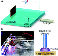
Fig. 1 depicts the structure of the experimental setup and the phenomenon of the static liquid metal electrode triggered discharge plasma. In our experiments, the liquid metal used as the soft electrode was Ga75.5In24.5 alloy, which consists of 75.5% gallium and 24.5% indium by weight. This proportion achieves an eutectic alloy with a melting point of 15 °C.
image file: c6ra23238h-f1.tif
Fig. 1 (a) Platform structure for triggering discharge plasma in liquid with a static liquid metal electrode. (b) Image of plasma triggered by the static liquid metal electrode.

As shown in Fig. 1a, the rectangular culture dish is filled with sodium dodecyl sulfate (SDS) with a concentration of 10 g L−1 and a copper plate is placed perpendicular to the dish bottom. The syringe needle is sheathed with a glass capillary tube filled with the liquid metal, which ensures that the plasma is induced by the liquid metal rather than the metal needle. The syringe needle is connected to the anode and the copper plate to the cathode of the power source so that a consistent DC voltage within 20 V could be applied when switched on. Part of the copper electrodes and the glass tube are immersed in the solution.

Pushing the syringe piston slightly, a liquid metal sphere with a diameter of about 1 mm appears on the tip of the glass tube. Upon turning on the power the water near the copper electrode begins to electrolyze, and then moves the syringe slowly forward. As shown in Fig. 1b and the ESI Movie 1, when the liquid metal sphere electrode nearly contacts the copper electrode, a blue-violet light with a special sound appears between the copper and the liquid metal electrodes. After that, it can be noticed that the underwater part of the copper plate is coated with a thin layer of silvery white alloy.

In order to compare the liquid metal soft electrode with the solid electrode intuitively, the liquid metal presented in Fig. 1a is replaced with a solid copper wire electrode of 0.3 mm diameter protected by a glass capillary tube. As shown in Fig. S1 and ESI Movie 2, different from the blue-violet light caused by the liquid metal electrode, when the tip of the copper wire just contacts the copper plate, a light also appears and after that the copper wire is heated up fast.

2.2 Liquid metal stream triggered discharge plasma

Since the liquid metal is fluidic, it could be jetted as a continuous stream. Therefore, besides the static sphere electrode, another unique form of jetting stream electrode was also tried. As shown in Fig. 2a, slightly different from the experimental platform presented in Fig. 1, there is a pair of parallel copper plates positioned 5 cm away from each other submerged in water, one of which is attached to the needle of the syringe. To ensure consistent jetting, the syringe is fixed onto an ejector pump. The volume speed is set as 0.25 mL s−1, and the inner diameter of the needle orifice is 0.21 mm, thus the initial jetting speed of the liquid metal at the orifice is 7.2 m s−1. Different from the static liquid metal electrode, the optical emissions appear in the line of the liquid metal stream randomly (Fig. 2b). Fig. 2c shows the strength of a group of continuous light emissions from the plasma discharge over a period of 7 ms.
image file: c6ra23238h-f2.tif
Fig. 2 (a) Platform structure for triggering discharge plasma in liquid with the liquid metal stream electrode. (b) Image of plasma triggered by the liquid metal stream electrode. (c) High speed image record of a single period of the plasma from the lighting moment until disappearing. (d) The process of the charged jetting and the plasma.

As a unique effect, when the liquid metal is jetted into the surfactant solution, it splits into multiple droplets that are a few hundred micrometers in diameter.1 However, once the liquid metal is conducted to the positive end of a DC voltage, the result of the jetting becomes completely different. As shown in Fig. 2d, as the positive electrode in the circuit, the jetted liquid metal is unable to break apart and just moves forward in the form of a continuous stream or a chain (t = 484 ms) because the surface is oxidized rapidly. At the moment before the liquid metal stream hits the copper plate of the negative end, a discharge occurs and the plasma emits a blue-violet light (t = 485 ms). During the jetting period, the blue-violet light also bursts out at another part of the liquid metal stream where a gap exists (t = 489 ms). After the light, the stream at the positive end immediately breaks into some micro-droplets, which may result from a quick reduction on the stream surface. But soon, the liquid metal recovers to a continuous stream again until it contacts the negative end of the electric field, when the next discharge happens (t = 548 ms). All these events can also be clearly seen in ESI Movie 3.

What's more, usually, the jetting stream can only generate droplets that are a few hundred micrometers in diameter without the applied voltage.1 However, owing to the unique property of the anode in the plasma, the morphology of the products is unusual. Quantities of non-uniform droplets sized from a few micrometers to hundreds of nanometers can be observed in the plasma products (Fig. 3a). Lots of round micro-droplets with diameters of less than 10 μm can be found. There also exist many sub-micro droplets. It could be inferred that these micro or sub-micro droplets are formed owing to a shockwave from the discharge plasma. Except for these droplets, some oxide also exists in the residuals. The image of Fig. 3c shows a typical one, which is pea-shaped and reflects both the separation trend and the surface oxidization of the jetting stream. According to our previous work, SDS can be employed as the solution substance, which is a surfactant to prevent the produced liquid metal droplets from agglomeration. Therefore, this also implies a promising method to fabricate liquid metal micro-particles.


image file: c6ra23238h-f3.tif
Fig. 3 Some kinds of liquid metal production resulted from the plasma phenomena. (a) Liquid metal droplets with diameters of several micrometers. (b) Sub-micro liquid droplets with diameters of several hundred nanometers. (c) Liquid metal pea.

2.3 Characteristics of the liquid metal triggered discharge plasma in liquid

In this study, various aspects and parameters of the plasma phenomenon have been recorded (Fig. 4). Fig. 4a presents the optical spectrum of the spark emitted by the liquid metal discharge plasma. Eight obvious peaks (287.4 nm, 294.1 nm, 303.8 nm, 325.6 nm, 403.3 nm, 410.0 nm, 417.2 nm, and 451.1 nm) can be observed along the axis, which are mainly originated from the plasmas of gallium and indium.21 Among them, four peaks were located in the ultraviolet area. The strongest four peaks lie in the visible blue and violet region. As a comparison, the optical spectrum of the light induced by the copper wire electrode shown in Fig. S1 has also been measured and the result is shown in Fig. S2. The light is nearly white and the spectrum is continuous rather than isolated along the wavelength axis, which both imply the case of incandescence.
image file: c6ra23238h-f4.tif
Fig. 4 The characteristic of the plasma triggered by the soft electrode. (a) Optical emission spectrum of the liquid metal stream plasma in SDS solution and the element analysis. (b) A detailed waveform of the current (blue) and repetitive pulses in a larger time scale (red) induced by the plasma. (c) The sound wave (red) and its frequency spectrum (blue) of the crackling.

Furthermore, the plasma causes a transient high pulse in current, which climbs to about 20 A from 0 A and lasts for several milliseconds, as illustrated in Fig. 4b. The sudden increase and decrease of the current reveals the beginning and ending of the discharge, and during the plasma maintaining period, the current stays at a relatively stable level. Actually, the current oscillogram also reflects the trend of the voltage change at the plasma area, as it is measured from the resistor put in series in the loop. Over a larger time scale, it can be observed that such an electric pulse appears almost periodically when the jetting is consistent.

Similar to the voltage, the temperature in the plasma area is also hard to measure directly. Thus a thermal couple is placed at a distance of about 10 mm away from the contact point where the jetting stream and the copper plate meets. A slight rise of about 0.5 °C can be observed from the sensor after a single burst, which also reflects the energy of the plasma transmitted to the surrounding solution.

Furthermore, the plasma is accompanied with crackling, and the frequency analysis is shown in Fig. 4c. It can be noticed that the peaks of the sound spectrum are relatively sparse and the highest peak is located at 5.25 kHz. The pulse width is about 10 ms and the energy of the sound signal is mainly concentrated between 3 KHz and 7 KHz.

2.4 Changing conditions in the jetting

Further, a series of experiments with changed conditions, such as the electrode direction and solution constituent, were conducted to further investigate and clarify this fundamental phenomenon. As displayed in Fig. 5a and ESI Movie 4, when the liquid metal is connected to the cathode of the electric field and jets to the anode of the copper plate with the same distance and initial jetting speed, the stream breaks easily into micro-droplets and no plasma light is observed.
image file: c6ra23238h-f5.tif
Fig. 5 Close view of the liquid metal jetting stream to clarify the typical factors that influence the plasma phenomenon. (a) The liquid metal is jetted from the cathode to the anode of the circuit. (b) The stream is in deionized water. (c) The stream is in 0.25 mol L−1 NaCl solution.

Furthermore, we tried several different solutions to observe the influence of the solution constituents. The solution in Fig. 2 is an SDS solution, a weak electrolyte. When a voltage is applied, the weak conductivity of its solution would help the surface oxidation of the jetting stream of the liquid metal, so that the continuous stream would be harder to break before it reaches the copper plate to trigger the plasma. While in the deionized water, the stream would break more easily when traveling the same distance. Thus it can be observed that the plasma phenomena in the SDS solution are more frequent than those in the deionized water (see details in ESI Movie 5). The situation in the strong electrolyte solution (like NaCl) is just the opposite. Resulting from the strong conductivity of the solution, the liquid metal is oxidized quickly and large quantities of black oxides emerge during the jetting (as seen in Fig. 5c and the ESI Movie 6), which also reduces the chance of plasma happening.

It is unusual for a discharge plasma to appear periodically in such a low voltage as 20 V in previous reports. Yet it can be seen that the liquid metal alloy still easily generates plasma light even when the voltage is as low as 10 V. Actually, as an important condition for triggering the plasma, the electric field must be strong enough. Besides the unique property of the alloy, from the low voltage it can be seen that the jetted electrode of the liquid metal ensures the continuous increase of the electric field till it is high enough, and the consistent stream maintains the repetitive plasma burst one after another.

3. Discussion

The basic elements of the plasma are particles from both the anode and the cathode. When an electric voltage is applied, in the first stage the electrons would release from the cathode into the liquid along the electric field and generate negative ions by attaching to an atom or molecule rapidly. The positive ions aggregate at the liquid metal anode because of the loss of the electrons. Then there is a current in the liquid. Initially, the intensity of the electric field is very weak when the distance between the positive and negative electrodes is far, and it only forms an electrolytic effect in which hydrogen is generated at the cathode and the liquid metal of the anode is oxidized. Together with the drawing near of the anode, the intensity of the electric field becomes rather high. At this time, a high puncture current is produced between both the electrodes, and the conduction of the plasma channel is formed. In the plasma, large quantities of electrons move to the anode, and the ions of the gallium and the indium also obtain enough momentum to move to the cathode. During this process, the collisions among the electrons, ions and atoms will induce discharge and light emission.

Actually, either solid or liquid metal would release positive ions under a strong electric field. Conventionally, this process relies on the structure of thin tips with thousands of volts applied, yet the emission of ions is usually a single beam.22–24 However, the fierce discharge plasma under such a low electric voltage is quite different. Owing to the drawing near of the electrodes, the intensity of the electric field between them increases greatly. The jetted electrode of the liquid metal just ensures the continuous increase of the electric field till it is high enough, and the consistent stream maintains the plasma burst one after another. Besides, compared with the solid metals, the ionized atoms in the liquid metal are much easier to break away from the metallic bonds, which soon accumulate and turn into a burst of charged particles. For the copper wire electrode, the contact of the electrodes is more likely to induce incandescence.

The liquid environment plays an important role, too. It ensures a current path before the discharge, which makes it harder for the jetting stream to break due to the surface oxidization. The experimental results have revealed that the discharge plasma happens in weak electrolyte solutions, since the high conductivity of the strong electrolyte solution would weaken the charge accumulation at the stream tip, causing less occurrence of the discharge. Yet when the polarity is reversed and the liquid metal is connected to the cathode, no oxide would form at its surface and the stream breaks easily. Thus the electric circuit is always disconnected for the liquid metal and there is no light-emitting plasma observed even if all the other parameters of the jetting stream are the same, which can be proven clearly by ESI Movies 3 and 4. Additionally, it should be noted that the liquid environment also provides cooling for these energy bursts, which prevents the solid electrode from melting and maintains the periodical appearance of the plasma.

Plasma in liquid is widely used in various fields, including material synthesis, environmental governance and biological sterilization. In addition, the plasma triggered by the liquid metal soft electrode suggests diverse potential applications. This method to produce plasma has also been demonstrated to be useful for the fabrication of micro size metal particles or other compounds. Additionally, it is a candidate for an easy-running light emitter for either optical or ultraviolet illuminations, or an electroacoustic source. Further, the rapid rise in voltage could result in strong electric field intensity during the process of discharge. Therefore, this plasma method might be capable of biological inactivation since the electric pulse and high energy ions could cause cell damage or mutation.

4. Experimental

The liquid metal used in the experiments was composed of 75.5% gallium and 24.5% indium. The two metals were placed in a beaker in proportion. The metals were heated to about 100 °C and mixed until thoroughly combined, then cooled to room temperature. The SDS solution was prepared with 99.0% purity SDS and deionized water by mixing and shaking, then heating to dissolve completely.

The optical emission spectrum was scanned with a fibre optic spectrometer (Ocean Optics USB2000, US). The temperature of the solution was obtained using thermocouples connected with a data acquisition instrument (Agilent 34970A, US). To measure the transient current in the circuit, a resistor of 0.1 Ω was put in series in the loop and an oscilloscope (Tektronix MSO2014, US) recorded its voltage change. The plasma fabrication movies were recorded using an ordinary camera (Canon XF305, Japan), and the high-speed images of 1000 fps were obtained for detailed analysis using a high-speed camera (NR4-S3 Camera, US). The sound was extracted from the movies of the plasma fabrication process.

These micro or sub-micro droplets resulted from the plasma phenomena were carefully observed with the assistance of a confocal laser scanning microscope (Nikon A1RSi, Japan).

5. Conclusions

In summary, according to the experiments, the discharge plasma of the liquid metal soft electrode is quite unusual compared with other plasma phenomena since it is induced under a low voltage. Although each burst only lasts for a few milliseconds, it repeats consistently during the jetting. It is also inspiring that such a strategy can be adopted to study the behaviours of the conductive liquid metal under other external fields. For further exploration, we might be able to change the element composition in the liquid metal alloy as well as the surrounding fluid, from which we hope to discover more evidence and even the mechanisms that control the plasma properties. Overall, with a couple of combined complicated factors related to mechanical, chemical, electrical, optical and acoustic effects inside, the present phenomenon has raised both very fundamental and practical issues worth pursuing in the future.

Acknowledgements

This research was funded by the National Natural Science Foundation of China (51605472), the Key Laboratory of Cryogenics of TIPC (CRYOQN201503), Director's Research Funding of TIPC (2016-WQ) and Dean's Research Funding of the CAS (2015-LJ).

References

  1. Y. Yu, Q. Wang, L. T. Yi and J. Liu, Adv. Eng. Mater., 2014, 16, 255 CrossRef CAS.
  2. W. Q. Fang, Z. Z. He and J. Liu, Appl. Phys. Lett., 2014, 105, 134104 CrossRef.
  3. S. Y. Tang, V. Sivan, K. Khoshmanesh, A. P. Omullane, X. Tang, B. Gol, N. Eshtiaghi, F. Lieder, P. Petersen, A. Mitchell and K. Kalantarzadeh, Nanoscale, 2013, 5, 5949–5957 RSC.
  4. L. Sheng, J. Zhang and J. Liu, Adv. Mater., 2014, 26, 6036–6042 CrossRef CAS PubMed.
  5. J. Zhang, L. Sheng and J. Liu, Sci. Rep., 2014, 4, 7116 CrossRef PubMed.
  6. X. K. Tang, S. Y. Tang, V. Sivan, W. Zhang, A. Mitchell, K. K. Zadeh and K. Khoshmanesh, Appl. Phys. Lett., 2013, 103, 174104 Search PubMed.
  7. L. Wang and J. Liu, RSC Adv., 2016, 6, 60729–60735 RSC.
  8. J. Zhang, Y. Y. Yao, L. Sheng and J. Liu, Adv. Mater., 2015, 27, 2648–2655 CrossRef CAS PubMed.
  9. C. Richmonds and R. M. Sankaran, Appl. Phys. Lett., 2008, 93, 131501 CrossRef.
  10. M. Banno, K. Kanno and H. Yui, RSC Adv, 2016, 6, 16030–16036 RSC.
  11. X. Lu, S. Wu, J. Gou and Y. Pan, Sci. Rep., 2014, 4, 7488 CrossRef CAS PubMed.
  12. P. Attri, B. Arora and E. H. Choi, RSC Adv., 2013, 3, 12540–12567 RSC.
  13. K. R. Stalder, J. Woloszko, I. G. Brown and C. D. Smith, Appl. Phys. Lett., 2001, 79, 4503–4505 CrossRef CAS.
  14. W. S. Kang, M. Hur and Y. H. Song, Appl. Phys. Lett., 2015, 107, 094101 CrossRef.
  15. M. A. Purvis, V. N. Shlyaptsev, R. Hollinger, C. Bargsten, A. Pulkhov, A. Prieto, Y. Wang, B. M. Luther, L. Yin, S. Wang and J. J. Rocca, Nat. Photonics, 2013, 7, 796–800 CrossRef CAS.
  16. P. A. C. Jansson, B. A. M. Hansson, O. Hemberg, M. Otendal, A. Holmberg, J. De Groot and H. M. Hertz, Appl. Phys. Lett., 2004, 84, 2256–2258 CrossRef CAS.
  17. S. Nomura, H. Toyota, S. Mukasa, H. Yamashita, T. Maehara and M. Kuramoto, Appl. Phys. Lett., 2006, 88, 211503 CrossRef.
  18. Y. Wu, P. Qiao, T. C. Chong and Z. Shen, Adv. Mater, 2002, 14, 64–67 CrossRef CAS.
  19. A. Starikovskiy, Y. Yang, Y. I. Cho and A. Fridman, Plasma Sources Sci. Technol., 2011, 20, 024003 CrossRef.
  20. C. Poulain, A. Dugué, A. Durieux, N. Sadeghi and J. Duplat, Appl. Phys. Lett., 2015, 107, 064101 CrossRef.
  21. C. Q. Wang and W. Chen, ICP-AES Spectrum of Common Elements (in Chinese), Metallurgical Industry Press, Beijing, 1994, p. 9 Search PubMed.
  22. R. G. Forbest, Vacuum, 1997, 48, 85–97 CrossRef CAS.
  23. V. G. Suvorov and R. G. Forbes, Microelectron. Eng., 2004, 73–74, 126–131 CrossRef CAS.
  24. C. A. Volkert and A. M. Minor, MRS Bull., 2007, 32, 389–399 CrossRef CAS.

Footnotes

Electronic supplementary information (ESI) available. See DOI: 10.1039/c6ra23238h
These two authors contribute equally to this work.

This journal is © The Royal Society of Chemistry 2016
Click here to see how this site uses Cookies. View our privacy policy here.