
Poly(3,4-ethylenedioxythiophene) (PEDOT) infused TiO2 nanofibers: the role of hole transport layer in photocatalytic degradation of phenazopyridine as a pharmaceutical contaminant
Jian Liua,
Danielle L. McCarthy a,
Linyue Tonga,
Michael J. Cowana,
John M. Kinsleya,
Laura Sonnenberga,
Kenneth H. Skorenkoa,
Steven M. Boyera,
Jared B. DeCosteb,
William E. Berniera and
Wayne E. Jones Jr.*a
a,
Linyue Tonga,
Michael J. Cowana,
John M. Kinsleya,
Laura Sonnenberga,
Kenneth H. Skorenkoa,
Steven M. Boyera,
Jared B. DeCosteb,
William E. Berniera and
Wayne E. Jones Jr.*a
aDepartment of Chemistry, Binghamton University-State University of New York, Binghamton, New York 13902, USA. E-mail: wjones@binghamton.edu; Fax: +1-607-777-4478; Tel: +1-607-777-2421
bEdgewood Chemical Biological Center, 5183 Blackhawk Road, Aberdeen Proving Ground, Maryland 21010, USA
First published on 1st December 2016
Abstract
Pharmaceuticals and personal care products are commonly discarded into environmental waters through sewers with human waste or by direct disposal causing serious contamination. Photocatalytic degradation of phenazopyridine (PAP) as a model pharmaceutical contaminant was investigated using TiO2 nanofibers and hybrid PEDOT infused TiO2 nanofibers. A novel material of PEDOT infused TiO2 nanofibers was fabricated via electrospinning and calcination to form TiO2 followed by the introduction of PEDOT using vapor phase polymerization. By changing the calcination temperature, the phase composition in TiO2 nanofibers can be adjusted to pure anatase phase, mixed phase and pure rutile phase. The photocatalytic activities of TiO2 nanofibers before and after PEDOT polymerization were measured by monitoring the decreasing concentration of PAP in aqueous solution under UV illumination using UV-Vis absorption spectroscopy. PEDOT infused TiO2 nanofibers showed an improved photocatalytic performance compared to their non-PEDOT infused counterparts for the degradation of PAP. This improvement can be attributed to the introduction of hole transport layer of PEDOT leading to an enhanced hole transfer from the TiO2 nanofibers to PEDOT. PEDOT infused rutile nanofiber has the most degradation enhancement (125%) compared to other two types of fibers (70% for PEDOT infused anatase & 30% for PEDOT infused mixed-phase).
1. Introduction
Pharmaceuticals and personal care products (PPCPs) have been recently regarded as an emerging class of aquatic contaminants. Hospitals, pharmaceutical production factories, private clinics and nursing homes are growing sources of this type of contamination.1,2 PPCPs, many of which are considered hazardous and toxic, are disposed into aquatic environments through direct disposal or accidental leaking from pharmaceutical producers. The major concerns of PPCPs result from their biological activity leading to adverse effects on aquatic ecosystems. Conventional techniques, such as dilution and incineration3 are insufficient to remove PPCPs from aquatic environments thoroughly. New methodologies that can remove PPCP contaminations at the source, before they go into the environment, are required.Many pharmaceutical pollutants have been found to be resistant to rigorous biodegradation systems. Photochemical degradation is a green method for the decomposition of PPCPs into small, non-toxic molecules more compatible with aquatic ecosystems. Owing to their pronounced photocatalytic performances, TiO2 materials have been identified as particularly important for use as photocatalysts.4,5 Their photocatalytic efficiency has been described as two competing processes:4 redox reactions of adsorbed species with photoexcited carriers (electrons and holes) and electron/hole pair recombination. Thus, the efficiency can be improved by suppressing the recombination process to prolong the lifetime of the redox carriers.
Several approaches have been used to improve the photodegradation efficiency of TiO2 materials by separating the electron/hole pairs and suppressing the recombination process, such as coupling semiconductors with different energy levels6–9 and the introduction of electron or hole conducting materials.10–15 Our previous study16 on the role of ruthenium photosensitizers in the degradation of phenazopyridine with TiO2 electrospun fibers suggested that the electron transfer from the conduction band of TiO2 doesn't play a major role in the degradation of PAP. It is possible to improve the overall degradation efficiency by introducing a hole transport material to TiO2 nanofibers. Johansson et al.17 demonstrated that the introduction of a hole conducting material is advantageous for fast hole transport to the interface without recombination with electrons in the TiO2 nanoparticles of dye sensitized solar cells (DSSC) leading to higher energy conversion efficiency. It is hypothesized that higher photocatalytic performance will be obtained by combining hole transport layer with TiO2 nanofibers.
As a unique class of π-conjugated materials, conducting polymers (CP) have received great attention due to their organic semi-conducting properties, leading to their applications in field-effect transistors, chemical sensors and photovoltaic cells. While there are many different CPs, PEDOT is appealing due to its ease of synthesis, environmental stability, flexible morphology, visible transparency and high electrical conductivity. Besides, PEDOT shows an excellent-stability under the presence of oxidative species, such as hydroxyl radicals.18–20 Primarily, four methods have been used to prepare PEDOT materials, including vapor-phase polymerization (VPP), chemical vapor deposition (CVD), in situ polymerization and electrochemical deposition.21–23 Due to these superior properties of PEDOT, it is widely used as a hole conducting material in sensors,24 photovoltaic devices,25 pseudo-capacitors22 and photocatalysts.26–28 Li Zhang et al.26 successfully synthesized PEDOT/GO/MnO2 nanocomposites, which showed a higher degradation efficiency of MB, suggesting the degradation efficiency of MB solution influenced by the synergic effects of PEDOT, GO and MnO2. In addition, the weight percentage of PEDOT in the composites also affected the overall photodegradation performance. Archana Dagar et al.27 studied the photodegradation of methyl orange by PEDOT/NiO/Fly. 2% PEDOT/NiO/FAC showed the highest degradation of methyl orange. Tursun Abdiryim et al.28 investigated the photocatalytic activities of PEDOT/ZnO composites by the degradation of methylene blue in aqueous medium. The highest photocatalytic efficiency occurred in PEDOT/15 wt% ZnO nanocomposite.
Here, we describe a simple approach to fabricate hybrid PEDOT infused TiO2 nanofibers via electrospinning and calcination of TiO2 nanofibers followed by the introduction of PEDOT using VPP. To the best of our knowledge, this is the first report on the photocatalytic degradation of PAP by coupling TiO2 materials with hole conducting polymer. By varying the calcination temperature, the phase composition in TiO2 nanofibers can be adjusted to have varied compositions of pure anatase, mixed phase or pure rutile.29 These nanofibers were applied to the photocatalytic degradation of a model pharmaceutical agent, phenazopyridine-[2,6-diamino-3-(phenylazo)-pyridine hydrochloride, (PAP)] (Scheme 1), which is used commercially as an analgesic for urinary tract infections.30,31 We report on the introduction of PEDOT leading to an enhanced photocatalytic performance of the hybrid fibers by improving the rate of transformation of photogenerated holes. PEDOT infused mixed-phase nanofiber has the least degradation enhancement (30%) compared to other two types of fibers (70% for PEDOT infused anatase & 125% for PEDOT infused rutile). This result comes from higher possibilities of electron back transferring from TiO2 to PEDOT leading to more electron/hole recombination in PEDOT infused mixed-phase fibers than other two types of fibers. Physical characterization, combined with the determination of initial degradation rates, provides insight into the mechanism for decontaminating toxic pharmaceutical agents in aqueous waste streams by PEDOT infused TiO2 nanofibers and their potential application for the degradation of industrial and environmental pollutants.
 | ||
| Scheme 1 The chemical structure of phenazopyridine. | ||
2. Experimental
2.1 Materials
Polymethylmethacrylate (PMMA) (Mw = 350![[thin space (1/6-em)]](https://www.rsc.org/images/entities/char_2009.gif) 000 g mol−1), chloroform, titanium isopropoxide (TTIP), N,N-dimethylformamide anhydrous (DMF), phenazopyridine hydrochloride (PAP), 3,4-ethylenedioxythiophene (EDOT), iron(III) p-toluenesulfonate hexahydrate (Fe(PTS)3·6(H2O)) were purchased from Sigma-Aldrich. Pyridine and n-butanol was purchased from Fisher Scientific. Ethanol was obtained from Pharmco-Aaper.
000 g mol−1), chloroform, titanium isopropoxide (TTIP), N,N-dimethylformamide anhydrous (DMF), phenazopyridine hydrochloride (PAP), 3,4-ethylenedioxythiophene (EDOT), iron(III) p-toluenesulfonate hexahydrate (Fe(PTS)3·6(H2O)) were purchased from Sigma-Aldrich. Pyridine and n-butanol was purchased from Fisher Scientific. Ethanol was obtained from Pharmco-Aaper.
2.2 Fabrication of PEDOT infused TiO2 nanofibers
The procedure for the fabrication of PEDOT infused TiO2 nanofibers is shown in Fig. 1. TiO2 fibers were prepared using a typical sol–gel synthesis followed by electrospinning of polymer sol–gel and calcination treatment of polymer fibers, which we have discussed in depth elsewhere.29 A polymeric sol–gel was generated by stirring and hydrolysis of TTIP using 1:2 mass ratio of PMMA:TTIP, where 320 mg of PMMA was completely dissolved in 2 mL of chloroform followed by drop wise addition of 640 mg of TTIP with continuous stirring for 30 min. 2 mL of DMF was then added and stirred for another 2 h to increase the dielectric constant of the composite solution to aid in the electrospinning process. The pre-calcined polymer fibers were fabricated using a high voltage Spellman SL 30 generator, where a high electrical potential was applied across the syringe needle attached to a copper wire and the collector screen. The resulting polymer fibers were left overnight to allow for complete hydrolysis of TTIP to Ti(OH)4 and further condensation to amorphous TiO2.32 This was followed by calcination at various temperatures to control the TiO2 crystal phases and morphology. By adjusting the calcination temperature from 300 to 700 °C for 4 h, TiO2 nanofibers with varying phase contents can be fabricated under ambient atmosphere.
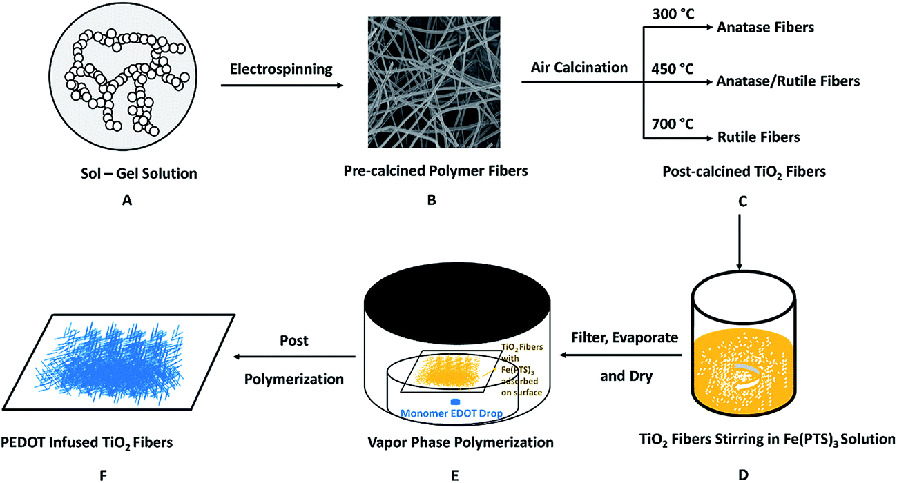 | ||
| Fig. 1 Schematic figure showing the preparation of PEDOT infused TiO2 nanofibers. (A) Sol–gel solution containing PMMA, precursor TTIP and the solvents; (B) post-electrospinned polymer fibers containing PMMA, amorphous TiO2 and solvent without evaporating; (C) post-calcined TiO2 nanofibers under different calcination temperatures with different phase compositions; (D) stirring of post-calcined TiO2 nanofibers with yellow oxidant Fe(PTS)3 solution; (E) dried TiO2 nanofibers with adsorbed Fe(PTS)3 on surface were put in a heated chamber for VPP reaction; (F) bluish dried PEDOT infused TiO2 nanofibers on filter paper. | ||
0.50 g of the oxidant Fe(PTS)3·6(H2O) was dissolved in 5 mL n-butanol to get a 0.15 M solution under sufficient stirring. 30 μL of pyridine was added to the oxidant solution as a basic inhibitor to suppress an acid-initiated polymerization reaction. Then 50 mg post-calcined TiO2 nanofibers (pure anatase, mixed phase or pure rutile) were added into 2 mL above oxidant solution and stirred for 1 h continuously. After dispersing homogeneously, the TiO2 nanofibers were filtered and dried to completely evaporate the solvent. The dried TiO2 nanofibers were then put on filter paper over a Petri dish containing a 100 μL EDOT drop, which was heated in an oven at the polymerization temperature of 50 °C. After the TiO2 fibers were exposed to EDOT vapor for 1 h, the whole set was taken out of the oven to terminate the polymerization process. The TiO2 nanofibers were then soaked in ethanol overnight to remove excess Fe(PTS)3, pyridine and residual EDOT. The samples were left under ambient conditions until completely dried before use as photocatalysts.
2.3 Characterization
The morphological and structural characteristics of the PEDOT infused TiO2 nanofibers were measured using field emission scanning electron microscope (FESEM, Supra 55 VP from Zeiss equipped with an EDAX energy dispersive X-ray spectroscopy detector), and Raman spectroscope (Thermo Scientific DXR Raman microscope with the laser wavelength of 532 nm) from wavenumber of 50 to 3200 cm−1, respectively. Thermogravimetric analysis (TGA) was done using a Netzsch TG 209 F1 Iris with QMS 403 Aëolos, at a ramp rate of 20 °C min−1 from room temperature to 750 °C under air. Optical absorption spectra were recorded using a JASCO V-650 UV-Vis spectrophotometer with the ILV-724 integrating sphere accessory from 200–800 nm with a data interval of 1 nm and a scan rate of 200 nm min−1.2.4 Photodegradation procedure
Photodegradation experiments were performed using an Oriel 66001 UV lamp with an Oriel 68805 40–200 Watt Universal Arc lamp power supply, which covered the UV range from 100 to 400 nm. UV-Visible analysis was performed on an 8452A Hewlett Packard Diode Array spectrophotometer from 190 to 820 nm of each aliquot from the photodegradation experiments to determine the PAP concentration. Sample analyses for photodegradation were performed in distilled water unless otherwise noted. 12 mL of a 144 μM PAP aqueous solution was transferred into a 16 mL cylindrical quartz container and placed in the dark. Next, 12 mg of photocatalyst (pure PEDOT or TiO2 nanofibers before and after PEDOT polymerization) was added to the PAP solution with constant stirring for 60 min to reach adsorption–desorption equilibrium. Then, a 1.0 mL aliquot of the sample was taken and centrifuged for 15 min, which was recoded as sample t = 0 min. Once the sample at t = 0 min was taken, the UV lamp was turned on at a fixed distance of 9 cm from the center of the quartz cell, and 1.0 mL aliquots of sample were taken at certain intervals (10, 20, 30, 45 min) and centrifuged for 15 min. After blanking the UV-Vis spectrophotometer with distilled water in a quartz cell, 0.5 mL of the upper PAP solution after centrifuge was taken from the aliquots and diluted with 3.0 mL of distilled water. Absorbance spectra were taken for the diluted samples with the UV-Vis spectrophotometer for time degradation samples at t = 10, 20, 30, 45 min.3. Results & discussion
3.1 Characterization of PEDOT infused TiO2 nanofibers
Pre-calcined polymer fibers and post-calcined TiO2 fibers before and after PEDOT polymerization were investigated using SEM to identify changes on their surface morphologies. As shown in Fig. 2, each type of fibers before PEDOT polymerization had a uniform diameter and dispersed without evidence of aggregation. At least 20 fibers were selected from each type to measure and calculate the fibers' diameter. The diameter of the TiO2 fibers before polymerization decreased from 310 ± 32 to 233 ± 42 nm as the rutile phase increased as shown in Table 1. This decrease in diameter is related to the polymer matrix decomposition and the phase transition from anatase to rutile, which is accompanied by approximately a 10% decrease in the volume.29 Compared to the anatase fibers in Fig. 2c, the surface morphology of the rutile fibers in Fig. 2g is much smoother without a wrinkled surface morphology. In Fig. 2d, f and h, fibers after PEDOT polymerization showed a completely different surface morphology compared to the fibers before polymerization in Fig. 2c, e and g. PEDOT was formed and wrapped on the surface of fibers and it tended to connect between the fibers as well to form a net. Relative to the fibers before PEDOT polymerization, the diameter of fibers after PEDOT polymerization increased as shown in Table 1, which further confirmed the formation of PEDOT. | ||
| Fig. 2 SEM images of (a) pure PEDOT; (b) pre-calcined polymer fibers; (c) post-calcined anatase TiO2 fibers; (d) PEDOT infused anatase TiO2 fibers; (e) post-calcined mixed phase TiO2 fibers; (f) PEDOT infused mixed phase TiO2 fibers; (g) post-calcined rutile TiO2 fibers; (h) PEDOT infused rutile TiO2 fibers. | ||
| Sample in SEM image | Sample | Diameter (nm) |
|---|---|---|
| b | Pre-calcined polymer fiber | 407 ± 64 |
| c | Anatase TiO2 fiber | 310 ± 32 |
| d | PEDOT infused anatase TiO2 fiber | 412 ± 92 |
| e | Mixed phase TiO2 fiber | 264 ± 38 |
| f | PEDOT infused mixed phase TiO2 fiber | 363 ± 51 |
| g | Rutile TiO2 fiber | 233 ± 42 |
| h | PEDOT infused rutile TiO2 fiber | 269 ± 21 |
As shown in Fig. 3, Raman analysis was performed on pure PEDOT, pre-calcined polymer fibers, and TiO2 fibers before and after PEDOT polymerization. In Fig. 3a–c, Raman peaks can be detected at 1450, 1735, 2850, 2958, 3000 cm−1 in the pre-calcined polymer fibers, confirming the presence of the PMMA. For the Raman spectra of post-calcined TiO2 fibers with different phases, the PMMA peaks are not present, consistent with complete combustion of PMMA during the calcination process. The anatase phase shows characteristic Raman peaks at 146, 393, 509 and 630 cm−1, while the rutile phase shows Raman peaks at 234, 443 and 606 cm−1. The Raman spectra confirmed the phase of TiO2 fibers in Fig. 3a and c to be anatase and rutile, respectively, while Fig. 3b is a mix of the two phases. Raman spectra of TiO2 fibers after soaking in Fe(PTS)3 showed several peaks between 1000 and 3200 cm−1, which belonged to Fe(PTS)3. After PEDOT polymerization, these peaks disappear leaving characteristic PEDOT peaks around 1500 cm−1. The absence of Fe(PTS)3 peaks in PEDOT infused TiO2 fibers also confirmed the successful removal of excess oxidant after the VPP process. The Raman spectrum of PEDOT infused TiO2 fibers include all the major peaks associated with PEDOT at 1250 cm−1 (Cα–C′α stretch), 1360 cm−1 (Cβ![[double bond, length as m-dash]](https://www.rsc.org/images/entities/char_e001.gif) Cβ stretch), 1430 cm−1 (CαCβ symmetric stretch), 1500 cm−1 (CαCβ asymmetric stretch) and 1550 cm−1 (bi-polaron state).22,23
Cβ stretch), 1430 cm−1 (CαCβ symmetric stretch), 1500 cm−1 (CαCβ asymmetric stretch) and 1550 cm−1 (bi-polaron state).22,23
 | ||
| Fig. 3 (a–c) Raman spectra of pure PEDOT, pre-calcined polymer fibers, post-calcined TiO2 fibers, TiO2 fibers soaked in Fe(PTS)3 and PEDOT infused TiO2 fibers; (d) the detailed spectra of the PEDOT infused fibers from 1000 to 2000 cm−1. | ||
TGA measurements were performed on pre-calcined polymer fibers and post-calcined TiO2 fibers before and after PEDOT polymerization with the results shown in Fig. 4a. For pre-calcined polymer fibers, the TGA curve shows that a 13% weight loss was observed before 285 °C from the adsorbed solvent and surface water on the fibers. PMMA started to decompose around 285 °C and the decomposition continued until 370 °C. The pre-calcined polymer fibers contained approximately 56% PMMA. Between 370 and 750 °C, no further weight loss was observed and 31% of the sample remained. It was considered as TiO2 with amorphous phase coming from TTIP hydrolysis. For post-calcined TiO2 fibers with no PEDOT, the three TGA curves show similar characteristics with no dramatic weight loss observed between room temperature and 750 °C, indicating there is no PMMA remaining in the post-calcined TiO2 fibers. It further confirmed that PMMA polymer matrix decomposed during the calcination process leaving pure TiO2 fibers.
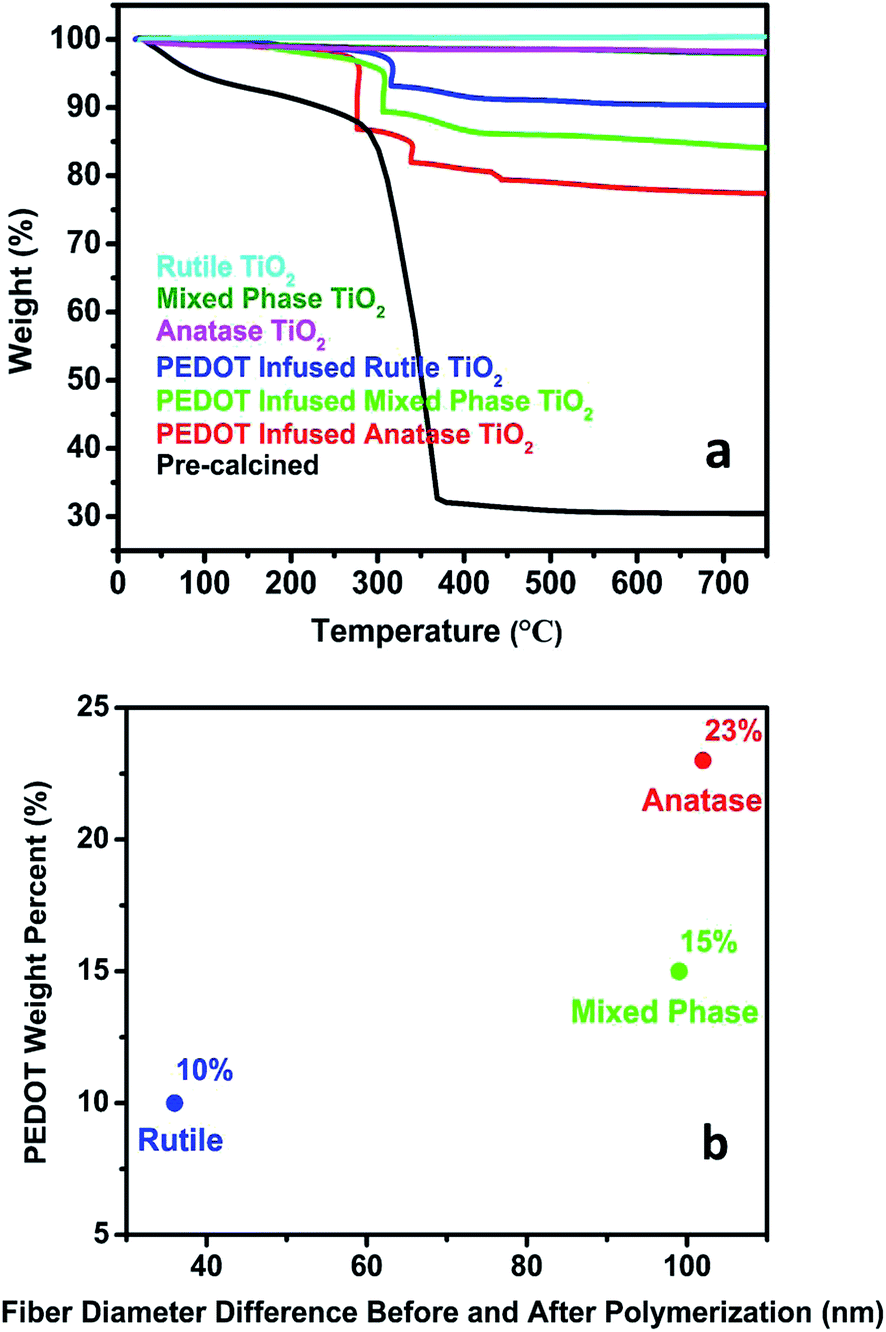 | ||
| Fig. 4 (a) TGA curves of pre-calcined polymer fibers and post-calcined TiO2 fibers before and after PEDOT polymerization; (b) relationship between PEDOT weight percent and fiber diameter differences before and after polymerization. | ||
TGA curves of PEDOT infused TiO2 fibers showed dramatic weight losses between the temperature of 200 and 450 °C. Since pure TiO2 fibers showed no weight decrease between room temperature and 750 °C, the weight loss indicates the decomposition of PEDOT. Based on the TGA results, the weight loss was dependent on the phase of TiO2 fibers. As shown in Fig. 4b, PEDOT infused rutile TiO2 fibers have the smallest weight loss of approximately 10 wt% while PEDOT infused anatase TiO2 fibers have approximately 23 wt%. This result suggests that more than twice the weight of PEDOT was formed on anatase TiO2 fibers compared to PEDOT on rutile TiO2 fibers, leading to larger diameter increase of anatase nanofibers after polymerization compared to other types of nanofibers shown in Table 1. This difference may result from the variable surface areas and pore volumes of TiO2 fibers with different phases. Previous studies have shown that as the rutile phase weight fraction relative to anatase phase in the fibers increases the fibers' surface area and pore volume decrease.29 Anatase TiO2 fibers with higher surface area and larger pore volume will provide higher possibility for more oxidant (Fe(PTS)3) to be adsorbed on the surface and to be infused inside the fibers, which will subsequently react with more EDOT vapor and form more PEDOT.
3.2 Photocatalytic activity
In order to investigate the role of PEDOT on the photodegradation activities, degradation experiments were performed under UV irradiation using various photocatalysts and monitoring the PAP concentration change based on the solution UV-Vis spectrum, as shown in Fig. 5a. Pure PAP solution was very stable under UV illumination showing no decomposition over 45 min. Pure PEDOT was prepared on Al foil and peeled off following the same VPP polymerization procedure as the PEDOT infused TiO2 nanofibers. The peeled PEDOT was tested as a control photocatalyst for the degradation of PAP. The PAP concentration was relatively stable under these conditions. A slight increase in absorbance was observed over time, which might be due to UV-Vis scattering of PEDOT residue in later aliquots. This result indicated that PEDOT itself does not degrade PAP. From TiO2 nanofibers before PEDOT polymerization, the mixed-phase TiO2 nanofibers showed a faster photocatalytic performance than pure anatase or rutile nanofibers. This result is consistent with previous studies showing the synergistic effect between anatase and rutile optimizes their photocatalytic activities.29 After PEDOT was introduced into the TiO2 nanofibers, the photocatalytic performance of all types of the PEDOT infused TiO2 nanofibers is dramatically enhanced. | ||
| Fig. 5 (a) PAP concentration changes based on solution UV-Vis spectra under UV irradiation using different photocatalysts; (b) PAP degradation data best fit as a pseudo-first-order reaction; (c) initial 30 min degradation rate constants calculated from the first-order rate plots; (d) initial 30 min degradation rate constants enhancement by using PEDOT infused TiO2 nanofibers compared to bare TiO2 nanofibers. (e) Influence of PEDOT weight percent on initial 30 min degradation rate constants enhancement. | ||
The degradation data from Fig. 5a could be best fit as a pseudo-first-order reaction. The rate constant and the kinetic equation can be expressed as C = C0e−kt, where t is the reaction time, k is the rate constant, C0 is the PAP initial concentration and C is the PAP concentration at reaction time of t. In Fig. 5b, the ln(C/C0) was plotted as a function of time t. The initial degradation rate constant, k, during the first 30 min degradation period for each of the TiO2 nanofibers was calculated. The relationship between the initial rate constant and the type of fiber is also shown in Fig. 5c. From Fig. 5d, it shows within the first 30 min under UV irradiation, PEDOT infused anatase, PEDOT infused mixed-phase and PEDOT infused rutile nanofibers showed a 70%, 30%, and 125% photodegradation enhancement respectively in the degradation rate constant compared to bare TiO2 nanofibers. The PEDOT infused anatase fibers exhibit the highest initial degradation rate constant of 0.034 min−1 among these fibers. In Fig. 5e, it is shown that highest weight percent of PEDOT was obtained on anatase nanofibers and their initial rate constant got enhanced most on rutile nanofibers containing the lowest weight percent of PEDOT. This result comes from the synergistic effect between TiO2 and PEDOT. In theory, more PEDOT on TiO2 nanofibers will provide more opportunities to enhance holes transfer from TiO2 to PEDOT. Since the same amount of photocatalysts were used in all the experiments, the higher PEDOT weight percent means lower TiO2 weight percent in the photocatalysts. Nanofibers with lower TiO2 weight percent should generate less electron/hole pairs, which will reduce the holes transfer and subsequently decrease their photodegradation efficiency.
The band gap of TiO2 nanofibers and PEDOT infused TiO2 nanofibers were determined from optical absorption spectrum recorded by a UV spectrophotometer compatible for solid sample analysis. (αhν)2 was used as y axis to plot for the indirect band gap transitions from TiO2. As shown in Fig. 6, the band gap energy of TiO2 nanofibers before PEDOT polymerization were determined to be 3.15, 3.06, and 3.04 eV with increasing rutile weight fraction. This is consistent with previous studies on the rutile fraction influence of the band gap of TiO2 nanofibers.29 The band gap of PEDOT infused TiO2 nanofibers had a dramatic decrease compared to bare TiO2 nanofibers, which are 3.05, 3.03 and 3.01 eV for PEDOT infused anatase nanofibers, PEDOT infused mixed-phase nanofibers and PEDOT infused rutile nanofibers, respectively. This shift can be elucidated as a consequence of PEDOT influences.
 | ||
| Fig. 6 Plot of (αhν)2 versus photon energy for calculating band gap energy of TiO2 nanofibers before and after PEDOT polymerization. | ||
3.3 Mechanism
Fig. 7a–c shows a possible mechanism of charge transfer during the photodegradation of PAP using PEDOT infused anatase, mixed phase and rutile fibers, respectively. Degradation working mechanisms using PEDOT infused anatase fibers (Fig. 7a) and PEDOT infused rutile fibers (Fig. 7c) are very similar. PEDOT:PSS used in the organic solar cells has been shown to have a HOMO level of approximately 5.1 eV.33–35 When PEDOT infused anatase (rutile) fibers are illuminated under UV light, only electrons in the valence band of the anatase (rutile) fibers are excited sufficiently to generate electron/hole pairs. Since the HOMO of PEDOT is very close to the conduction band of the anatase (rutile) fibers, electrons in the HOMO of PEDOT can easily migrate into the anatase (rutile) fibers leaving behind active holes in PEDOT. As shown in Fig. 7a and c, holes trapped in the valence band of anatase (rutile) could react with H2O to form hydroxyl radicals. The electrons trapped on the surface of anatase (rutile) fibers could react with adsorbed O2 to form superoxide radical anions. Both of these radicals are oxidants, among which the hydroxyl radical is an extremely powerful and indiscriminate oxidant. Hydroxyl radical can rapidly attack pollutants at the surface or in solution.36 These oxidizing radicals react with PAP leading to the cleavage of the azo linkage and decomposition into smaller molecules.37 Compared to pure anatase (rutile) fibers, PEDOT infused anatase (rutile) fibers generate more electrons and holes under UV irradiation, increasing the formation of more active radicals to enhance the photocatalytic performance. Electrons located in HOMO of PEDOT will get excited to LUMO level and migrate to conduction band of anatase (rutile) phase. Meanwhile, holes transfer will happen between valence band of anatase (rutile) and HOMO of PEDOT. These electrons/holes migration will improve charge separation by reducing their recombination and subsequently enhance their photocatalytic performance. However, the transferred electrons form conduction band of anatase (rutile) may migrate back to HOMO of PEDOT resulting the electron/hole recombination. Since the conduction band of anatase and HOMO of PEDOT have the same energy level, this recombination process will be faster and easier to happen in PEDOT infused anatase fiber than PEDOT infused rutile fibers. This explains why PEDOT infused anatase fibers has a lower photocatalytic enhancement (70%) than PEDOT infused rutile fibers (125%). | ||
| Fig. 7 Proposed schematic representation of possible electron–hole separation pathway mechanism for PEDOT infused TiO2 fibers during the photodegradation process of PAP. | ||
Recently, a new understanding of the band alignment between rutile and anatase showed that the electron affinity of anatase was higher than rutile.38 This suggests that it is thermodynamically favorable for electron transfer from rutile to anatase to enhance electron/hole pairs' separation during the photodegradation process of PAP. This helps explain why mixed phase TiO2 fibers have a faster initial degradation rate than either pure anatase or rutile fibers.29 Under UV illumination, excited electrons and holes in PEDOT infused mixed phase TiO2 fibers are further separated into the conduction band of anatase and HOMO of PEDOT, respectively. The separation dramatically improves their photocatalytic performance. As shown in Fig. 7b, within PEDOT infused mixed-phase nanofibers, PEDOT may directly contact with anatase phase or rutile phase. However, the photocatalytic performance of PEDOT infused mixed-phase nanofibers didn't have a better improvement compared to PEDOT infused anatase (rutile) nanofibers. The electron back transfer shown by the red arrow, may happen from both conduction bands of rutile and anatase phases to HOMO of PEDOT. These electron/hole pair recombination both hamper the further improvement of their photocatalytic performance. This explains the reason why PEDOT mixed-phase nanofibers has the least degradation enhancement (30%) compared to other two types of fibers (70% for PEDOT infused anatase & 125% for PEDOT infused rutile).
4. Conclusion
PEDOT infused TiO2 nanofibers were successfully fabricated via electrospinning of TiO2 followed by calcination and VPP of PEDOT. By raising the calcination temperature, the phase composition of the TiO2 fibers was adjusted from pure anatase, to a mixed phase and finally pure rutile. In each case, the PEDOT infused TiO2 nanofibers exhibits a higher initial degradation rate constant than their non-PEDOT infused counterparts for the degradation of PAP. This improvement can be attributed to the introduction of hole transport layer of PEDOT leading to an enhanced hole transfer from the TiO2 nanofibers to PEDOT. PEDOT mixed-phase nanofibers has the least degradation enhancement (30%) compared to other two types of fibers (70% for PEDOT infused anatase & 125% for PEDOT infused rutile). The back transfer of electrons from TiO2 fibers to PEDOT generated the electron/hole pair recombination, which adversely hampered the further enhancement of photocatalytic performance. This study provides insights into the design of hole transport materials for further enhancement on the degradation performance of pharmaceutical pollutants using TiO2 materials as well as other photocatalysts.Acknowledgements
We acknowledge funding from the National Science Foundation under grant number IIP-1318202, Strategic Partnership for Industrial Resurgence (SPIR) and the Army Research Office (ARO) W911NF1310235. Additional funding was provided by the Joint Science and Technology Office for Chemical Biological Defense (JSTO-CBD) under contract BA13PHM210 at the Edgewood Chemical Biological Center. This experimental work has been carried out with support from the Department of Chemistry at Binghamton University, State University of New York.References
- F. Abdulla, H. A. Qdais and A. Rabi, Waste Management, 2008, 28, 450–458 CrossRef PubMed.
- Q. Frederic and P. Yves, Chemosphere, 2014, 115, 31–39 CrossRef PubMed.
- H. S. Hilal, G. Y. Al-Nour, A. Zyoud, M. H. Helal and I. Saadeddin, Solid State Sci., 2010, 12, 578–586 CrossRef CAS.
- M. A. Henderson, Surf. Sci. Rep., 2011, 66, 185–297 CrossRef CAS.
- K. Ozawa, M. Emori, S. Yamamoto, R. Yukawa, S. Yamamoto, R. Hobara, K. Fujikawa, H. Sakama and I. Matsuda, J. Phys. Chem. Lett., 2014, 5, 1953–1957 CrossRef CAS PubMed.
- D. Robert, Catal. Today, 2007, 122, 20–26 CrossRef CAS.
- H. Zhang, G. Chen and D. W. Behnemann, J. Mater. Chem., 2009, 19, 5089–5121 RSC.
- M. D. Hernàndez-Alonso, F. Fresno, S. Suaàrez and J. M. Coronado, Energy Environ. Sci., 2009, 2, 1231–1257 Search PubMed.
- M. Ilieva, A. Nakova and V. Tsakova, J. Appl. Electrochem., 2012, 42, 121–129 CrossRef CAS.
- Y. C. Si and E. T. Samulski, Chem. Mater., 2008, 20, 6792–6797 CrossRef CAS.
- E. Yoo, T. Okata, T. Akita, M. Kohyama, J. Nakamura and I. Honma, Nano Lett., 2009, 9, 2255–2259 CrossRef CAS PubMed.
- G. M. Scheuermann, L. Rumi, P. Steurer, W. Bannwarth and R. Mulhaupt, J. Am. Chem. Soc., 2009, 131, 8262–8270 CrossRef CAS PubMed.
- S. J. Guo, S. J. Dong and E. W. Wang, ACS Nano, 2010, 4, 547–555 CrossRef CAS PubMed.
- S. Y. Wang, X. Wang and S. P. Jiang, Phys. Chem. Chem. Phys., 2011, 13, 6883–6891 RSC.
- B. Y. Xia, H. B. Wu, J. S. Chen, Z. Wang, X. Wang and X. W. Lou, Phys. Chem. Chem. Phys., 2012, 14, 473–476 RSC.
- S. M. Boyer, J. Liu, S. Zhang, M. I. Ehrlich, D. L. McCarthy, L. Tong, J. B. DeCoste, W. E. Bernier and W. E. Jones Jr, J. Photochem. Photobiol., A, 2016, 329, 46–53 CrossRef CAS.
- E. M. J. Johansson, L. Yang, E. Gabrielsson, P. W. Lohse, G. Boschloo, L. Sun and A. Hagfeldt, J. Phys. Chem. C, 2012, 116, 18070–18078 CAS.
- Y. Lattach, A. D. Besseau, J. M. Guigner and S. Remita, Radiat. Phys. Chem., 2013, 82, 44–53 CrossRef CAS.
- F. Goubard, P. H. Aubert, K. Boukerma, E. Pauthe and C. Chevrot, Chem. Commun., 2008, 3139–3141 RSC.
- C. Coletta, Z. Cui, P. Archirel, P. Pernot, J. L. Marignier and S. Remita, J. Phys. Chem. B, 2015, 119, 5282–5298 CrossRef CAS PubMed.
- D. C. Martin, J. Wu, C. M. Shaw, Z. King, S. A. Spanninga, S. Richardson-Burns, J. Hendricks and J. Yang, Polym. Rev., 2010, 50, 340–384 CrossRef CAS.
- L. Tong, K. H. Skorenko, A. C. Faucett, S. Boyer, J. Liu, J. M. Mativetsky, W. E. Bernier and W. E. Jones, J. Power Sources, 2015, 297, 195–201 CrossRef CAS.
- K. H. Skorenko, S. Faucett, J. Liu, N. A. Ravvin, W. E. Bernier, J. M. Mativetsky and W. E. Jones, Synth. Met., 2015, 209, 297–303 CrossRef CAS.
- H. Yoon, M. Chang and J. Jang, Adv. Funct. Mater., 2007, 17, 431–436 CrossRef CAS.
- S. Choi, J. H. Boo, H. Sohn and S. Kim, J. Nanosci. Nanotechnol., 2014, 14, 9005–9010 CrossRef CAS PubMed.
- L. Zhang, R. Jamal, Q. Zhao, M. Wang and T. Abdiryim, Nanoscale Res. Lett., 2015, 10, 148–156 CrossRef PubMed.
- A. Dagar and A. K. Narula, Mater. Chem. Phys., 2016, 183, 561–570 CrossRef CAS.
- T. Abdiryim, A. Ali, R. Jamal, Y. Osman and Y. Zhang, Nanoscale Res. Lett., 2014, 9, 89–96 CrossRef PubMed.
- J. Liu, D. L. McCarthy, M. J. Cowan, E. A. Obuya, J. B. DeCoste, K. H. Skorenko, L. Tong, S. M. Boyer, W. E. Bernier and W. E. Jones, Appl. Catal., B, 2016, 187, 154–162 CrossRef CAS.
- M. Citak, S. Yilmaz, Y. Dilgin, G. Turker, S. Yagmur, H. Erdugan and N. Erdugan, Curr. Pharm. Anal., 2007, 3, 141–145 CrossRef CAS.
- S. Yagmur, S. Yilmaz, M. Sadikoglu, G. Saglikoglu, M. Yildiz, C. Yengin and E. Kilinc, Int. J. Electrochem. Sci., 2013, 8, 6818–6828 CAS.
- S. Mahshid, M. Askari and M. S. Ghamsari, J. Mater. Process. Technol., 2007, 189, 296–300 CrossRef CAS.
- H. J. Lee, G. Anoop, H. J. Lee, C. Kim, J. Park, J. Choi, H. Kim, Y. Kim, E. Lee, S. Lee, Y. Kim, J. Lee and J. Y. Jo, Energy Environ. Sci., 2016, 9, 2806–2811 CAS.
- A. Garcia, G. C. Welch, E. L. Ratcliff, D. S. Ginley, G. C. Bazan and D. C. Olson, Adv. Mater., 2012, 24, 5368–5373 CrossRef CAS PubMed.
- C. W. Lee, O. Y. Kim and J. Y. Lee, J. Ind. Eng. Chem., 2014, 20, 1198–1208 CrossRef CAS.
- S. Sun, J. Ding, J. Bao, C. Gao, Z. Qi and C. Li, Catal. Lett., 2010, 137, 239–246 CrossRef CAS.
- M. Fathinia and A. Khataee, Appl. Catal., A, 2015, 491, 136–154 CrossRef CAS.
- D. O. Scanlon, C. W. Dunnill, J. Buckeridge, S. A. Shevlin, A. J. Logsdail, S. M. Woodley, C. R. A. Catlow, M. J. Powell, R. G. Palgrave, I. P. Parkin, G. W. Watson, T. W. Keal, P. Sherwood, A. Walsh and A. A. Sokol, Nat. Mater., 2013, 12, 798–801 CrossRef CAS PubMed.
| This journal is © The Royal Society of Chemistry 2016 |