Direct amide synthesis over core–shell TiO2@NiFe2O4 catalysts in a continuous flow radiofrequency-heated reactor

Yawen Liua, Pengzhao Gaob, Nikolay Cherkasova and Evgeny V. Rebrov*ac
aSchool of Engineering, University of Warwick, Coventry CV4 7AL, UK. E-mail: E.Rebrov@warwick.ac.uk
bCollege of Materials Science and Engineering, Hunan University, Changsha 410082, China
cDepartment of Biotechnology and Chemistry, Tver State Technical University, Nab. A. Nikitina 22, 170026, Russia

Received 10th September 2016 , Accepted 17th October 2016

First published on 17th October 2016


Abstract

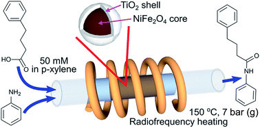
Core–shell composite magnetic catalysts TiO2@NiFe2O4 with a titania loading of 9–32 wt% have been synthesised by a sol–gel method for direct amide synthesis in a radiofrequency (RF, induction)-heated continuous flow reactor. The catalyst calcination temperature was optimised in the range of 350–500 °C and the highest activity was observed for the catalyst calcined at 500 °C due to conversion of titania into the catalytically active anatase phase. No reaction between the magnetic core and the titania shell was observed up to the calcination temperature of 1000 °C and no sintering of the titania shell was observed after calcination at 500 °C. The comparison of direct amide synthesis in a continuous flow fixed bed reactor under conventional and RF heating demonstrated that the RF heating mode increased the apparent reaction rate by 60% and decreased the deactivation rate due to a better temperature uniformity. The titania weight normalised reaction rate in the RF-heated reactor was constant for titania loadings above 17 wt%, while it decreased by a factor of 3 at lower titania loadings because of interactions between the ferrite core on the thin layer of the catalyst. The catalyst deactivation study showed that the deactivation rate could be accurately described by first order kinetics and that the main reason of deactivation was coking. The catalyst regeneration via calcination at 400 °C resulted in catalyst sintering, while treatment with a hydrogen peroxide solution at 90 °C fully recovered the catalytic activity.


1. Introduction

Synthesis of amide molecules is essential in pharmaceutical, medical, biological as well as polymer industries.1–3 In the pharmaceutical industry in particular, the synthesis of 65% of drug candidates involves amide bond formation.4 However, traditional amide synthesis routes require either the synthesis of halogen derivatives or application of coupling agents in order to facilitate the reaction under relatively mild conditions.3,5,6 The main drawback of this approach is the utilization of large, often stoichiometric, amounts of expensive, toxic, halogenated agents which require additional separation stages, resulting in poor atom economy and generation of large amounts of toxic waste. This problem was recognized as one of the most topical problems of pharmaceutical synthesis.4

A desired scenario for the amide synthesis, the direct reaction between readily available carboxylic acids and amines, is currently very limited because (i) thermal (non-catalytic) synthesis of amides in this way is only possible for a very limited range of reactants, (ii) it requires long reaction time and (iii) high temperature which is usually unacceptable for thermo liable pharmaceutical molecules.7–9 For example, the amide yield in the reaction between aniline and 4-phenylbutyric acid after 48 h is as low as 4% at 120 °C.8 To increase the reaction rate, many metal oxides demonstrated catalytic activity such as CeO2, CaO, MgO, ZnO, Y2O3, TiO2, ZrO2, Nb2O5, Al2O3, SiO2 (ref. 10–13) as well as solid acids like Amberlyst-15, HBEA, niobic acid, mont-K10, Nafion–SiO2 and IBA.10,14 Among them, titania provides a unique combination of low price and high catalytic activity.15–17 Hosseini-Sarvari et al.15 applied nanosized sulfated titania to direct amide synthesis in a batch reactor using a wide range of substrates and obtained the yields of 70–98% in 3–12 h at 115 °C. Nagarajan et al.16 demonstrated quick (under 30 min) amide synthesis with the yields ranging from 83 to 98% using sulfated titania nanotubes at 110 °C. Microwave heating applied by Gaudino et al.18 resulted in the product yields over 55% at 100 °C within 60 min over a commercial P25 TiO2 catalyst.

The literature data shows that the application of titania catalysts in direct amide synthesis allows for high amide yields within the reaction time of less than an hour at moderately high reaction temperatures. However, the efficiency of widely studied batch processes is limited for such reaction conditions. In particular, low heat transfer rates via reactor walls in stirred tank reactors may result in non-uniform temperature profile in large reactors with a possibility of hot spot formation in stagnant zones resulting in accelerated catalyst deactivation. Moreover, an inefficient mechanism of heat transfer, conduction through the reactor walls and convection through the reaction solution, results in high energy consumption and increases product costs. A promising solution to these problems lies with the combination of (i) continuous flow processing coupled with (ii) radiofrequency (RF)-heated reactors.

Small volume of continuous flow reactors provide a substantial increase in heat and mass transfer rates increasing utilization efficiency of the equipment.19,20 In addition, flow reactors are intrinsically safe because a rupture of the reactor wall operating even under high pressure results in the release of minute amounts of hazardous substances. This allows for safe handling dangerous materials or a drastic expansion of possible reaction conditions.21 These advantages result in process intensification, an increase in reaction rates per reactor volume by a factor of 2 to 1000 compared to conventionally used batch systems.21 As a result, flow reactors with a millilitre-range diameter could produce kilogram quantities of product when operated for a whole day.22 Flow reactors easily allow to reach and exploit intrinsic limitations on product selectivity of the catalysts, resulting in an increased economic efficiency of the processes.19,23,24

Despite of these advantages, there are very few works which studied amide synthesis in continuous flow. Mascia et al.25 demonstrated a more than 6-fold decrease in the reaction time (from 300 to 47 h) in a flow compared to a batch reactor using in a homogeneously acid-catalysed reaction of an anhydride with an amine. Furthermore, the overall reaction apparatus was simplified in flow reducing the number of unit operations from 21 to 14 mainly due to simplification in the downstream steps such as pharmaceutical formulation, mixing and granulation. Gustafsson et al.26 showed feasibility of flow synthesis for a wide range of amides using highly reactive trimethylaluminium agent. Liu and Jensen27 combined heterogeneous oxidation, gas–liquid separation and oxidation amination for the synthesis of amides from amines and alcohols. However, the complexity of the system required may be a limitation of the approach. Comerford et al.13 showed the feasibility of the direct amide synthesis from 4-phenylbutyric acid and aniline in continuous flow over an acidic silica catalyst.

The problem of low energy efficiency, which is vital for the processes operating in the temperature above 100 °C on a large scale, can be significantly improved using non-conventional heating sources like microwave or RF heating.28 Moreover, when heat is transferred from the walls, the temperature gradient through the cross section may lead to lower temperature in the central part, resulting in low reaction rates. Recently, the RF-heated continuous flow reactor where heat is generated by the magnetic particles in the alternating magnetic field has been applied in the organic synthesis.29–32 As heat is uniformly generated over the entire catalyst volume, it provides much a smaller radial temperature gradient and reduced heat loss to the environment. Additionally, Ceylan et al.29 has demonstrated higher yields (80 vs. 65%) of organic reactions conducted in an RF-heated reactor compared to that in a conventional continuous flow reactor. RF heating also provides a further advantage of catalyst separation simply using a magnet, decreasing the recycle costs of heterogeneous catalysts.33–35

In our previous contribution, we reported feasibility of the direct amide synthesis conducted in an RF-heated continuous reactor packed with a P25 titania/nickel ferrite catalyst obtained by solid state synthesis.32 The amide yield of 35% was demonstrated with optimisation of ball milling time performed. However, the approach of a mixed composite (catalytic and magnetic) particles has its intrinsic limitations. Firstly, magnetic nanoparticles exposed to the reaction medium can be corroded in solutions with high acidity or alkalinity, which decreases the catalyst lifetime and may result in by-product formation. Secondly, the ball milling step used for catalyst preparation provides high mechanical impact on titania nanoparticles resulting in poor control of the catalyst morphology and low surface area. Both problems can be solved with the application of a core–shell catalyst which avoids these problems and has been proved to be efficient in a range of chemistries.36–38 The aim of this work was to obtain a TiO2@NiFe2O4 magnetic composite catalyst with a core–shell structure for direct amide synthesis in an RF-heated continuous reactor, and to optimise its heating and catalytic properties.

2. Experimental

2.1 Synthesis of composite catalysts

The nickel ferrite nanoparticles were synthesized by a sol–gel method.39 A solution of 51.69 g iron(III) nitrate nonahydrate, 18.6 g nickel(II) nitrate hexahydrate in 250 mL ethanol was mixed with a solution of 36.9 g citric acid in 150 mL ethanol. After stirring the mixture for 24 h, a 2 M ammonia solution was added dropwise to adjust the pH to 2. Under stirring, the temperature was increased to 90 °C to evaporate the solvent until the total volume decreased to about 150 mL. The slurry was dried further in an oven at 90 °C, grinded and then calcined in air at 700 °C for 1 h with a heating rate of 2 °C min−1. The obtained material (3 g) was dispersed under ultrasound in 300 mL water/ethanol (20[thin space (1/6-em)]:[thin space (1/6-em)]80 v/v) solution of 1 M ammonia and 3 mM cetyltrimethylammonium bromide (CTAB).

The titania sol was prepared mixing 85 mL tetrabutyl titanate, 25 mL diethanolamine and 285 mL ethanol followed by hydrolysis under vigorous stirring caused by dropwise (20 mL h−1) addition of a water/ethanol solution (10 mL/100 mL). The resulting translucent sol was left aging for 24 h under stirring at room temperature and then without stirring for another 24 h.

The core–shell composite catalysts were prepared by adding dropwise (20 mL h−1) the titania sol obtained into the suspension of NiFe2O4 nanoparticles under vigorous stirring. The solid material obtained was centrifuged, washed with ethanol (3 × 20 mL), dried in air at 70 °C overnight and calcined in air at the desired temperature for 1 h with a heating rate of 1 °C min−1. The samples obtained are referred to as T-X-Y where index X is the measured titania loading (wt%) and Y is the calcination temperature in °C. The first indexes are different for the catalysts recovered after the reaction: spent catalyst (ST); regenerated with a 30 wt% aqueous solution of H2O2, chemically-treated (CT); and thermally regenerated catalysts, thermally-treated (TT).

2.2 Catalyst characterization

Powder X-ray diffraction (XRD) study was performed using a PANalytical Empyrean diffractometer with a Fe-filtered Co Kα radiation (0.179 nm) with a scanning rate of 2° 2θ min−1. The resulting data were re-calculated into Cu wavelength (0.154 nm) for proper comparison with literature data. The infrared spectra were recorded in transmission mode in the 2000–400 cm−1 range and a resolution of 2 cm−1 using an Avatar360 Nicolet IR spectrometer. The catalysts (3–5 mg) were mixed with KBr (3–5 mg), pressed into self-supporting wafers and placed in an in situ cell with CaF2 windows.

The TiO2 content in the composite catalysts was determined via an energy dispersive spectrometry (EDS) using a Jeol JSM-6700F scanning electron microscope (Table 1). The powdered materials were applied on an adhesive conductive tape and studied without additional metal coating. The catalyst morphology was studied with a Philips, Tecnan F20 transmission electron microscope operated at 200 kV. The catalysts were dispersed in ethanol under sonication and a droplet of the suspension was applied on the carbon-coated copper grids.

Table 1 Titania in the catalysts studied: nominal (ωnominal) and determined by EDS (ωEDS)
Sample ωnominal (wt%) ωEDS (wt%)
T-9-400 7.4 8.9
T-17-400 13.9 16.7
T-26-400 24.3 26.0
T-32-400 32.5 32.0


The as-synthesized samples (20 mg) were characterized by combined thermogravimetric and differential thermal analysis (TG-DTA) on a STA 449 C Netzsch Analyser in a 10 mL min−1 flow of 20 vol% O2/N2 and a heating rate of 10 °C min−1. The temperature programmed oxidation analysis was performed for the spent samples placing 50 mg of the sample into a U-shaped quartz tube between plugs of quartz wool. After waiting for 1 h at 25 °C in the flow of N2, the flow was switched to a mixture containing 1 vol% O2, 1 vol% Ar (internal standard), and 98 vol% N2 and the temperature was increased linearly at a rate of 10 °C min−1. The concentrations of CO, CO2 and H2O were recorded by a quadrupole mass spectrometer.

The magnetic properties of the catalyst were measured at room temperature using a vibrating sample magnetometer, Princeton Measurements Corporation MicroMag 3900 VSM, equipped with a 2 T electromagnet. The saturation magnetization (Ms) was evaluated from the hysteresis loop. The specific absorption rate (SAR) under the RF field was determined as the initial thermal power of the catalyst under RF heating. An insulated glass tube was loaded with 10 mg sample and 50 μL water, placed in the middle of a 5-turn coil and heated with a RF generator (Easyheat 0112, current 200 A). A fibre optics temperature sensor inserted into the sample recorded the temperature increase and the first 30 s of linear temperature increase was used for (SAR) calculation.39

2.3 Catalytic activity testing

The catalytic activity of the composite catalysts was measured in the amide synthesis in a 160 mL Parr continuously stirred tank reactor. The catalyst, 680 mg, and the reactants, 50 mM aniline, 50 mM 4-phenylbutyric acid (PBA), 50 mM tetradecane (internal standard) in 100 mL p-xylene, were added into the reactor. The reactor was purged with N2 on stirring, pressurised to 6 bar with N2 and heated to 150 °C. The reaction was carried out at a stirring rate of about 950 min−1. The samples (1–2 mL) were collected at regular intervals. A series of experiments with various stirring rates and catalyst weights confirmed the absence of mass transfer limitations.

The optimized TiO2@NiFe2O4 catalysts were tested in a continuous flow reactor. The catalyst, 320 mg, pressed and sieved to obtain the fraction of 125–250 μm, was placed in the central part of the reactor forming a catalyst bed with a length of 5 mm. To preheat the reactant solution, a 5 mm preheating section consisting of catalytically inert iron oxide pellets (pellet size: 125–250 μm) was placed before the catalyst bed. A Fiso FOT-L-SD optic fibre temperature sensor was attached to the outer surface of the reactor, which was insulated with a 1 cm thick layer of glass wool and placed into an 8-turn induction coil connected to an RF generator operating at 223 kHz (Easyheat). The electric current of the RF generator was controlled with a PID controller to provide a constant bed temperature.

The reaction under conventional heating was performed using a resistive heating wire as a heating source. To account for slow conductive heat transfer, the length of the initial pre-heating zone was increased to insure that the inlet feed reaches the catalyst bed at the desired reaction temperature. The p-xylene solutions of aniline (100 mM) and 4-phenylbutyric acid (100 mM along with 100 mM of tetradecane) were introduced into the reactor at a desired flow rate using two Shimadzu LC-20AD HPLC pumps. The outlet pressure was maintained at 7 bar (gauge) with a back pressure controller to allow operation at temperatures above the normal boiling point of p-xylene. The samples collected were analysed using a gas chromatograph (Shimadzu GC-2010) equipped a 30 m Stabilwax capillary column and a flame ionization detector.

No products other than N,4-diphenylbutanamide were observed and the carbon balance was better than 98% according to the scheme presented in Fig. 1. The reaction yield was found to be limited (to 60%) by the product solubility. Hence, all reactions were performed in the conversion range of 10–50% and the discussion was further focused on the reaction rates.


image file: c6ra22659k-f1.tif
Fig. 1 Reaction scheme of the N,4-diphenylbutyramide synthesis.

3. Results and discussion

3.1 Thermal behaviour

Fig. 2 shows TG-DTA curves of NiFe2O4 nanoparticles, dry TiO2 gel, and composite catalysts. In the studied temperature range, NiFe2O4 showed no change in weight and low thermal effect demonstrating that the stable phase was obtained by calcination at 700 °C, which is in agreement with the previous reports40,41 (Fig. 2a). For the TiO2 dry gel (Fig. 2b), adsorbed ethanol and water were removed in the temperature range of 75 to 165 °C. The decomposition of the precursors was observed in the range from 270 to 323 °C followed by oxidation of residual organic materials above 475 °C.42 The weight of TiO2 gel was constant above 570 °C indicating full removal of combustible materials. The composite catalysts demonstrated behaviour similar to that of the TiO2 dry gel (Fig. 2c) – a continuous weight loss in the temperature range below 570 °C was observed caused by the removal of solvents and organic precursors. The total weight loss increased from 10.2 to 25.1% proportionally to TiO2 content showing that organic materials were primarily adsorbed in the titania layer. The thermal effect above 570 °C in the composite materials was lower than that of NiFe2O4 showing the absence of solid–state reactions between the TiO2 framework and NiFe2O4 nanoparticles in the composite catalysts.
image file: c6ra22659k-f2.tif
Fig. 2 Thermogravimetric analysis (solid curves) and differential thermal analysis (dashed curves) of (a) NiFe2O4 (b) TiO2 dry gel (c) as-synthesised composite catalysts T-17-25, T-26-25 and T-32-25 with titania loadings of 16.7, 26 and 32 wt%, respectively.

3.2 Effect of TiO2 loading

Four composite catalysts with the TiO2 loading of 8.9, 16.7, 26.0 and 32.0 wt% have been prepared to investigate the effect of titania content on their activity and stability in the amide synthesis reaction. The actual TiO2 content was in good agreement with the nominal composition (Table 1), demonstrating efficient incorporation of TiO2 sol onto the magnetic nanoparticles. Nearly spherical particles were observed in TEM images of all samples (Fig. 3). The titania formed a layer around nickel ferrite nanoparticles (shown with arrows in Fig. 3b–d) with the thickness of about 5–10 nm. The incorporation of titania coating did not change the average dimensions of the NiFe2O4 core (40–60 nm in diameter), which agrees with the TGA data on the absence of chemical interaction between the core and the shell during the synthesis (Fig. 2).
image file: c6ra22659k-f3.tif
Fig. 3 TEM photographs of (a) initial nickel ferrite nanoparticles and (b–d) composite catalysts calcined at 400 °C with TiO2 loading of (b) 16.7 wt%, sample T-17-400, (c) 26 wt%, sample T-26-400, and (d) 32 wt%, sample T-32-400. Arrows point to the TiO2 shell as determined by EDS.

The infrared spectra of composite catalysts calcined at 400 °C along with the NiFe2O4 are shown in Fig. 4. In the spectrum of calcined pure TiO2 (T-100-400), very broad Ti–O–Ti framework stretching modes were observed in the range from 1000 to 400 cm−1.43–46 These vibrations were partially overlapped by the 590 cm−1 band of Fe–O stretching vibrations of NiFe2O4 in the composite catalysts.47,48 The intensity of the 590 cm−1 peak increased proportionally to NiFe2O4 content. Also the width of the Fe–O band, which was close for all composite catalysts, was noticeable broader compared to that of NiFe2O4. This broadening suggests a very close contact between NiFe2O4 and TiO2 and confirms the formation of the core–shell structure in agreement with the TEM data (Fig. 3).


image file: c6ra22659k-f4.tif
Fig. 4 FT-IR spectra of nickel ferrite nanoparticles, as-synthesised TiO2 (sample T-100-400) and composite catalysts calcined at 400 °C containing 8.9 wt% (sample T-9-400), 16.7 wt% (sample T-17-400), 26.0 wt% (sample T-26-400) and 32.0 wt% TiO2 (sample T-32-400). The spectra are shifted upwards for clarity.

The magnetisation curves of composite catalysts are shown in Fig. 5. All the studied composite catalysts showed the same coercivity of 0.2 kG. Because coercivity significantly depends on magnetic particle dimensions, the same coercivity for various catalysts shows that NiFe2O4 particle dimensions were not affected by the introduction of TiO2 shell, which is in agreement with TGA (Fig. 2) and TEM (Fig. 3) data. On increasing titania content, the saturation magnetization linearly decreases because of the decreasing amount of the magnetic NiFe2O4. The proportionality shows that the saturation magnetization is determined only by the nickel ferrite loading, which means that there is no additional loss of magnetism observed due to the formation of titania shell (see insert in Fig. 5). The specific absorption rate (SAR) of composite catalysts is directly proportional to the area of hysteresis loop between the magnetisation curves, decreasing from 1.08 to 0.88 W g−1 as TiO2 increased from 8.9 to 32 wt% (Table 2). These data demonstrate that the RF heating properties of the composite catalysts can be precisely controlled during the preparation stage.


image file: c6ra22659k-f5.tif
Fig. 5 Magnetization curves of composite catalysts with different TiO2 loading calcined at 400 °C.
Table 2 Specific BET surface area of pristine (SBET,initial) and spent (SBET,spent) composite catalysts and specific absorption rate (SAR) for the pristine catalystsa
Sample SBET,initial (m2 g−1) SBET,spent (m2 g−1) SAR (W g−1)
a n.d. – not determined.
T-26-25 44.9 n.d. 1.00
T-26-350 31.8 n.d. 0.73
T-26-400 30.7 n.d. 0.76
T-26-450 32.4 n.d. 0.86
T-26-500 35.1 26.7 0.87
T-9-500 21.9 15.6 1.08
T-17-500 25.0 20.0 1.05
T-32-500 51.9 40.8 0.88
P-25 50.5 n.d. 0.00


3.3 Effect of calcination temperature

The calcination temperature has a major influence on the phase composition of the resulting composite catalysts. The calcination step is necessary to remove the remaining structure directing agent (CTAB) from the porous network and the temperature should be sufficiently high for its full oxidation (Fig. 2). Moreover, the temperature should provide transition of titania into catalytically active anatase phase, but not high enough for the sintering or conversion into less active rutile phase.49,50 The effect of calcination temperature on specific surface area and specific absorption rate under RF heating was studied with the composite catalyst having a titania loading of 26 wt%. According to TGA analysis, the temperature around 500 °C was high enough to remove the surfactants. The literature shows that the formation of anatase takes place around 400 °C followed by its transition to rutile above 500 °C.51 Hence, the catalysts were calcined at temperatures of 350, 400, 450 and 500 °C to study phase composition and check for possible core–shell interaction. XRD spectra of the composite catalysts calcined at various temperatures are shown in Fig. 6. The formation of anatase phase started at 450 °C. The XRD peaks at 25.4 and 48.2° 2θ could be attributed to the (101), (200) crystal planes of anatase respectively (JCPDS card 78-2486). The crystallinity of TiO2 increased with an increase in the calcination temperature from 450 to 500 °C as it can be seen from the peak intensity of the characteristic anatase peaks at 25.4° 2θ. The peaks at 30.7, 36.0, 37.6, 43.8, 54.8, 58.1 and 64.4° 2θ were assigned to NiFe2O4 (JCPDS card 74-2081). The small peaks at 31.4 and 41.3° 2θ were assigned to the (220) and (113) crystal planes of α-Fe2O3 (JCPDS card 33-0664), which could be typically found as an impurity in the nickel ferrite.41 The size of NiFe2O4 crystallites in the catalysts was estimated using a Scherrer equation for the highest intensity (311) peak of NiFe2O4 to be 52–57 nm for the initial and calcined catalysts, which agreed with the TEM data. Hence, the calcination temperature of 450–500 °C was beneficial considering anatase formation, while neither core–shell interaction nor rutile formation occurred.
image file: c6ra22659k-f6.tif
Fig. 6 XRD patterns of nickel ferrite nanoparticles (NiFe2O4) and the composite catalysts containing 26 wt% titania uncalcined (T-26-25), calcined at 350 °C (T-26-350), 400 °C (T-26-400), 450 °C (T-26-450), 500 °C (T-26-500). The peaks are assigned to (N) NiFe2O4, (A) anatase titania, (H) hematite Fe2O3. The spectra are shifted upwards for clarity.

The specific surface area and SAR values of calcined catalysts are listed in Table 2. Comparing the catalysts calcined at various temperatures with the initial (T-26-25) catalyst, the specific surface area and SAR decreased by 30% after calcination at 350 °C. The decrease in the surface area was likely caused by condensation and densification of the amorphous titania network resulting in the increase in TiO2 particle sizes, which was observed for many porous materials.52–54

The decrease in SAR values on calcination requires some discussion of heating mechanisms. There are four mechanisms of heating in RF field: (i) Néel relaxation, (ii) Brownian rotation, (iii) hysteresis loss and (iv) eddy currents (significant only on the centimetre scale materials). The mechanisms were discussed in details in our review34 as well as in the review of Deatsch and Evans.55 Briefly, Brownian rotation is caused by rotation of magnetic particles in the field with the heat generated via shear stress of the surrounding fluid, Néel relaxation involves rotation of the magnetic moment without the particle movement, and hysteresis loss results in shifting of magnetic domains in multidomain materials.55,56 Hence, for the studied particles about of 50 nm in diameter, all three mechanisms are expected because the superparamagnetic and single domain diameters for NiFe2O4 are 28 and 100 nm, respectively.57,58

For the series of core–shell catalysts containing 26 wt% of titania, an increase in calcination temperature from 350 to 500 °C resulted in a minor increase in SAR values. A much higher value of the uncalcined materials T-26-25 might be caused by a significantly different surface properties which provide a stronger interaction with the solvent (water) resulting in a higher Brownian heat generation. Comparing the materials with different titania loading calcined at 500 °C, the SAR values decreased steadily with increasing titania content (Table 2). This phenomenon was obviously associated with the decrease in NiFe2O4 content as the SAR value for non-magnetic titania is 0.

3.4 Catalytic activity and stability

The catalytic activity of composite catalysts was studied in a stirred tank reactor (Fig. 7) with the reaction rates normalised for the weight of TiO2 in the composite catalysts. The reaction rate increased with the calcination temperature from 350 to 500 °C in agreement with the formation of catalytically active anatase phase observed by XRD study (Fig. 6). Remarkably, the samples calcined at 450 and 500 °C demonstrated similar reaction rates, which were 2.5 times higher than that over the catalyst calcined at 350 °C. An increase in the specific surface area for the T-26-500 compared to T-26-450 sample might have also contributed to a slightly increased reaction rate (Table 2). Importantly, the reaction rate over composite catalyst T-26-500 normalised per titania weight reached the value of that observed over the reference P25 catalyst. This clearly demonstrates that magnetic functionality can be introduced into catalysts without affecting their catalytic performance. It should be noted that in spite of a rather high reaction temperature of 150 °C and a single combination of acid and amine, the approach is suitable for a wide range of other substrates.63 We anticipate that for thermolabile substrates (such as chiral compounds) much lower reaction rates are expected as the temperature should be reduced far below 150 °C. Yet, the overall production rate can be kept similar by increasing the catalyst loading in the reactor. The current method allows fast and reproducible preparation of larger amounts of composite catalysts in a very reproducible way.
image file: c6ra22659k-f7.tif
Fig. 7 Reaction rate of amide synthesis over composite catalysts containing 26 wt% titania as a function of calcination temperature in a batch reactor. Reaction conditions: temperature: 150 °C, pressure: 6 bar, concentration of aniline: 0.05 M in p-xylene, concentration of 4-phenylbutyric acid: 0.05 M in p-xylene, catalyst weight: 680 mg, the dashed line designates the reaction rate over the commercial P-25 catalyst.

To transfer the process to a continuous flow reactor, the benefits of the RF heating were verified first. The performance of RF-heated and conventionally-heated fixed bed reactors filled with the same T-32-500 catalyst was compared (Fig. 8) showing an increase in the reaction rate by 60% in the RF-heated reactor. This difference increased further in the course of the reaction caused likely by different temperature distribution in the studied reactors. In the conventionally-heated flow reactor, heat was transferred from the outer surface via the reactor wall to the composite catalyst, which resulted in a radial temperature gradient in the reactor. On the contrary, the heat was released inside the composite catalyst particles in the RF-heated reactor. As the heated liquid flows downstream, this created an axial temperature gradient, which was reduced by placing inert particles between the catalyst zones.59,60 Therefore, one might conclude that the reaction rate could be improved without accelerating deactivation kinetics under RF heating.


image file: c6ra22659k-f8.tif
Fig. 8 Reaction rate of amide synthesis over the T-32-500 catalyst in conventionally and RF-heated flow reactors as a function of time on stream. Reaction conditions: aniline, 0.1 M in p-xylene at 20 μL min−1 and, 4-phenylbutyric acid, 0.1 M in p-xylene at 20 μL min−1 introduced in a fixed bed reactor at 150 °C, pressure 7 bar (g), catalyst weight, 320 mg.

To explore the effect of titania content, the catalytic activity of core–shell composite catalysts with different TiO2 loadings was studied in the RF-heated flow reactor. Because the SAR values of these catalysts were different, the intensity of magnetic field (electric current in the RF coil) was adjusted in these experiments to keep the same temperature of the reaction mixture as listed in Table 3. It can be seen that the RF power needed to maintain the reaction temperature increased from 101 to 142 W as the titania loading increased from 9 to 32 wt%. The initial reaction rate over the composites catalyst increased at a higher titania content which was expected because of the larger number of the available active sites. However, the initial reaction rate normalized by the weight of TiO2 showed that the T-9-500 catalyst had a much lower value while those over the other three samples were close to each other (Table 3). These data indicate that in case of a very thin catalyst shell there exists an interaction between the NiFe2O4 core and titania shell, which is detrimental for catalytic activity. A possible cause is the electronic interaction between TiO2 and ferrite referred to as photodissolution phenomenon, which was extensively reported in literature.61–64 When the thickness of titania shell increases, this detrimental effect becomes less pronounced as the relative contribution from the area near the core–shell interface decreases as compared to the total available surface area.

Table 3 The reaction rates over composite catalysts in the RF-heated flow reactor. Aniline, 0.1 M in p-xylene at 20 μL min−1 and, 4-phenylbutyric acid, 0.1 M in p-xylene at 20 μL min−1 introduced in a fixed bed reactor at 150 °C, pressure 7 bar (g), catalyst weight, 320 mg
Sample Power input (W) Initial reaction rate Initial specific reaction rate × 104 (μmol m−2 s−1) Specific reaction rate in spent catalyst × 104 (μmol m−2 s−1)
μmol g−1 s−1 μmol g-TiO2−1 s−1
T-9-500 101 0.0048 0.05 2.4 1.5
T-17-500 117 0.023 0.14 9.9 7.5
T-26-500 134 0.030 0.12 9.0 8.3
T-32-500 142 0.049 0.15 9.7 10.1


A strong deactivation was observed during the direct amide synthesis as shown in Fig. 8 and 9. The deactivation was likely caused by the formation of trace amounts of azobenzene species on the catalyst surface which readily decompose to form coke and block the catalyst surface.32,65 The deactivation was observed in both RF-heated and conventionally-heated reactors (Fig. 8). A similar effect was reported in the synthesis performed under microwave heating.66 The effect of titania loading on deactivation kinetics could be clearly seen when the reaction rate was normalized by the initial reaction rate (Fig. 9). Such deactivation behaviour was modelled using a first order kinetics considering slow deactivation caused by blockage of catalysts surface which was caused by the occurring chemical reaction.54,67 The corresponding deactivation rate a (reaction rate r normalised by the initial rate r0) is presented in eqn (1)

 
a = r/r0 = exp(−kdeactivt), (1)
where kdeactiv is the deactivation constant and t is time on stream.


image file: c6ra22659k-f9.tif
Fig. 9 (a) Normalized reaction rate as a function of time on stream and (b) deactivation rate constant as a function of titania loading in the RF-heated flow reactor. Reaction conditions: aniline, 0.1 M in p-xylene at 20 μL min−1 and, 4-phenylbutyric acid, 0.1 M in p-xylene at 20 μL min−1 introduced in a fixed bed reactor at 150 °C, pressure 7 bar (g), catalyst weight, 320 mg.

The values of the deactivation constant were inversely proportional to titania loading as shown in Fig. 9b. The deactivation rate constant for the catalyst containing 9 wt% titania was almost 3 times as high as for the catalyst containing 32 wt% titania. However, this result is not surprising considering that a blockage of an active site for the catalyst containing a small number of sites provides a much higher relative deactivation rate compared to the catalyst with a larger number of sites. In fact, the product of the deactivation constant and titania loading (number of active sites) was almost constant for the studied catalysts suggesting the same deactivation mechanism.

After 20 h on stream, the surface area of the spent catalysts decreased by 20–25% (Table 2). However the specific reaction rate (normalised per unit of surface area) remained virtually the same (9.7 × 10⁻⁴ vs. 10.1 × 10⁻⁴ μmol m−2 s−1) in the spent ST-32-500 catalyst having the highest titania loading while the reaction rate slightly reduced in the catalysts with lower titania loadings (Table 3). Hence, it can be concluded that both reduced surface area and site blockage are responsible for deactivation. These processes may occur separately or they can be caused by the same reason such as surface coking.

In order to study the deactivation mechanism, the temperature programmed oxidation (TPO) study of spent catalysts was performed. Fig. 10 shows CO2 profiles obtained in the TPO experiments over the spent catalysts. It should be mentioned that these concentration profiles were normalized per titania weight in the catalysts. The CO2 peaks at 260, 350 and 465 °C indicate three types of carbon species formed during the reaction. The amount of carbon species was the highest in the spent catalyst with the lowest titania loading and it gradually decreased as the amount of titania increased. The ST-9-500 catalyst had also the highest amount of strongly adsorbed carbon species which require a temperature in excess of 475 °C for their complete oxidation. The coke was likely formed on hot spots and required higher temperatures to be removed than the coke obtained on the catalysts with higher amounts of titania.


image file: c6ra22659k-f10.tif
Fig. 10 Normalized CO2 profiles over spent catalysts in TPO experiments with a heating rate of 5 °C min−1 in the flow of 20 vol% O2/N2.

The catalyst regeneration from coke is typically performed by calcination in air. The carbon from the spent T-32-500 catalyst can be fully removed by the calcination at 400 °C for 1 h as demonstrated by the TPO experiment (Fig. 11). However, even despite of very low calcination temperature, this procedure reduced the surface area in the regenerated catalyst by 12%, to 30.2 m2 g−1, likely because of sintering of the porous titania shell. As a result, the reaction rate in the amide synthesis over the recovered catalyst in the second catalytic run was not fully recovered after regeneration (Fig. 12).


image file: c6ra22659k-f11.tif
Fig. 11 CO2 profile over the spent ST-32-500 in a TPO experiment with a heating rate of 5 °C min−1 in the flow of 20 vol% O2/N2.

image file: c6ra22659k-f12.tif
Fig. 12 Reaction rate in the RF-heated flow reactor as a function of time over different composite catalysts: as synthesized T-32-500 catalyst, the same spent catalyst after calcination in air at 400 °C for 1 h (TT-32-500), and after chemical regeneration with hydrogen peroxide (CT-32-500) at 90 °C for 22 h. Reaction conditions: aniline, 0.1 M in p-xylene at 20 μL min−1 and, 4-phenylbutyric acid, 0.1 M in p-xylene at 20 μL min−1 introduced in a fixed bed reactor at 150 °C, pressure 7 bar (g), catalyst weight, 320 mg.

To minimise sintering, the catalyst regeneration temperature has to be decreased. Obviously, calcination in air cannot be performed at the temperature much lower than 400 °C (Fig. 11), hence other decoking agents should be employed. Querini et al.68 successfully used a hydrogen peroxide solution for catalyst regeneration as a low-temperature oxidation agent. Following this approach, the surface area of the regenerated composite catalyst was determined to be 48.5 m2 g−1, which was marginally lower than that in the fresh catalyst of 51.9 m2 g−1. The results of the catalyst testing of this mildly-regenerated catalysts (CT-32-500) show that the catalytic activity was fully restored (Fig. 12). Also the second catalytic run followed the same deactivation kinetics as the first run indicating that the catalyst was returned to the initial state after the treatment with the hydrogen peroxide solution. It can be concluded that the dominant deactivation mechanism is associated with the formation of coke.

4. Conclusions

Core–shell TiO2@NiFe2O4 composite catalysts have been prepared by sol–gel method. By adjusting the amount of titania precursor in the initial synthesis sol, it has been possible to precisely control titania loading as well as specific absorption rate of the catalysts. Thermogravimetric and X-ray studies showed that no chemical reaction occurs between the magnetic core and the catalytic titania shell below 500 °C. The optimisation of the catalyst calcination temperature demonstrated that the transition of titania into catalytically active anatase phase started at 450 °C, resulting in the highest catalytic activity of the catalyst calcined at 500 °C and no sintering of the titania shell was observed.

The catalytic activity was compared in the direct amide synthesis from aniline and 4-phenylbutyric acid in a fixed-bed continuous flow reactor under conventional heating and RF heating. The initial reaction rate was by 60% higher under RF heating. The deactivation rate was higher in the conventionally-heated reactor due to the presence of a radial temperature gradient. This allows significant process intensification in RF-heated reactors loaded with composite catalysts.

The catalyst deactivation behaviour was studied for a range of catalysts calcined at 500 °C and having various titania loading in the range of 9–32 wt%. The reaction rate normalised by titania weight was constant over the catalysts with titania loadings above 17 wt%. However, the catalyst with a 9 wt% titania loading showed significantly lower reaction rate because of a negative influence of the magnetic core onto the catalytic shell as a result of their electronic interaction near the interface. The catalyst deactivation rate was described by a first order kinetics demonstrating deactivation rate constant was inversely proportional to the thickness of titania shell.

The analysis of deactivated catalysts showed that coking was the main deactivation mechanism. The coke was fully removed by calcination in air at 400 °C leading to sintering of titania and a non-reversible catalyst deactivation. No sintering of titania was observed after the regeneration with a 30 wt% H2O2 solution at 90 °C. This regeneration procedure provided full recovery of the catalytic properties. It can be concluded that a combination of a core–shell composite catalyst with a continuous flow mode provides a promising way for direct amide synthesis with easy catalyst regeneration and magnetic separation.

Acknowledgements

The financial support provided by the European Research Council (ERC) project 279867 and the Russian Science Foundation project 15-13-20015 is gratefully acknowledged.

References

  1. J. S. Carey, D. Laffan, C. Thomson and M. T. Williams, Org. Biomol. Chem., 2006, 4, 2337–2347 CAS .
  2. J.-F. Soulé, H. Miyamura and S. Kobayashi, J. Am. Chem. Soc., 2011, 133, 18550–18553 CrossRef PubMed .
  3. V. R. Pattabiraman and J. W. Bode, Nature, 2011, 480, 471–479 CrossRef CAS PubMed .
  4. D. J. Constable, P. J. Dunn, J. D. Hayler, G. R. Humphrey, J. L. Leazer Jr, R. J. Linderman, K. Lorenz, J. Manley, B. A. Pearlman and A. Wells, Green Chem., 2007, 9, 411–420 RSC .
  5. E. Valeur and M. Bradley, Chem. Soc. Rev., 2009, 38, 606–631 RSC .
  6. C. Chen, F. Verpoort and Q. Y. Wu, RSC Adv., 2016, 6, 55599–55607 RSC .
  7. R. M. Lanigan, P. Starkov and T. D. Sheppard, J. Org. Chem., 2013, 78, 4512–4523 CrossRef CAS PubMed .
  8. H. Charville, D. A. Jackson, G. Hodges, A. Whiting and M. R. Wilson, Eur. J. Org. Chem., 2011, 2011, 5981–5990 CrossRef CAS .
  9. R. S. Varma and K. P. Naicker, Tetrahedron Lett., 1999, 40, 6177–6180 CrossRef CAS .
  10. S. H. Siddiki, A. S. Touchy, M. Tamura and K.-i. Shimizu, RSC Adv., 2014, 4, 35803–35807 RSC .
  11. F. Arena, C. Deiana, A. F. Lombardo, P. Ivanchenko, Y. Sakhno, G. Trunfio and G. Martra, Catal. Sci. Technol., 2015, 5, 1911–1918 CAS .
  12. P. S. Chaudhari, S. D. Salim, R. V. Sawant and K. G. Akamanchi, Green Chem., 2010, 12, 1707–1710 RSC .
  13. J. W. Comerford, J. H. Clark, D. J. Macquarrie and S. W. Breeden, Chem. Commun., 2009, 2562–2564 RSC .
  14. K. Arnold, A. S. Batsanov, B. Davies and A. Whiting, Green Chem., 2008, 10, 124–134 RSC .
  15. M. Hosseini-Sarvari, E. Sodagar and M. M. Doroodmand, J. Org. Chem., 2011, 76, 2853–2859 CrossRef CAS PubMed .
  16. S. Nagarajan, P. Ran, P. Shanmugavelan, M. Sathishkumar, A. Ponnuswamy and K. S. Nahm, New J. Chem., 2012, 36, 1312–1319 RSC .
  17. C. Deiana, Y. Sakhno, M. Fabbiani, M. Pazzi, M. Vincenti and G. Martra, ChemCatChem, 2013, 5, 2832–2834 CrossRef CAS .
  18. E. C. Gaudino, D. Carnaroglio, M. G. Nunes, L. Schmidt, E. Flores, C. Deiana, Y. Sakhno, G. Martra and G. Cravotto, Catal. Sci. Technol., 2014, 4, 1395–1399 Search PubMed .
  19. K. F. Jensen, Chem. Eng. Sci., 2001, 56, 293–303 CrossRef CAS .
  20. S. V. Ley, D. E. Fitzpatrick, R. Ingham and R. M. Myers, Angew. Chem., Int. Ed., 2015, 54, 3449–3464 CrossRef CAS PubMed .
  21. V. Hessel, D. Kralisch, N. Kockmann, T. Noel and Q. Wang, ChemSusChem, 2013, 6, 746–789 CrossRef CAS PubMed .
  22. N. Cherkasov, A. O. Ibhadon and E. V. Rebrov, Catal. Today, 2016, 273, 205–212 CrossRef CAS .
  23. D. M. Roberge, L. Ducry, N. Bieler, P. Cretton and B. Zimmermann, Chem. Eng. Technol., 2005, 28, 318–323 CrossRef CAS .
  24. N. Cherkasov, A. O. Ibhadon and E. V. Rebrov, Appl. Catal., A, 2016, 515, 108–115 CrossRef CAS .
  25. S. Mascia, P. L. Heider, H. Zhang, R. Lakerveld, B. Benyahia, P. I. Barton, R. D. Braatz, C. L. Cooney, J. Evans and T. F. Jamison, Angew. Chem., Int. Ed., 2013, 52, 12359–12363 CrossRef CAS PubMed .
  26. T. Gustafsson, F. Pontén and P. H. Seeberger, Chem. Commun., 2008, 1100–1102 RSC .
  27. X. Liu and K. F. Jensen, Green Chem., 2013, 15, 1538–1541 RSC .
  28. J. D. Moseley and C. O. Kappe, Green Chem., 2011, 13, 794–806 RSC .
  29. S. Ceylan, C. Friese, C. Lammel, K. Mazac and A. Kirschning, Angew. Chem., Int. Ed., 2008, 47, 8950–8953 CrossRef CAS PubMed .
  30. S. R. Chaudhuri, J. Hartwig, L. Kupracz, T. Kodanek, J. Wegner and A. Kirschning, Adv. Synth. Catal., 2014, 356, 3530–3538 CrossRef CAS .
  31. J. Hartwig, S. Ceylan, L. Kupracz, L. Coutable and A. Kirschning, Angew. Chem., Int. Ed., 2013, 52, 9813–9817 CrossRef CAS PubMed .
  32. T. K. Houlding, P. Gao, V. Degirmenci, K. Tchabanenko and E. V. Rebrov, Mater. Sci. Eng., B, 2015, 193, 175–180 CrossRef CAS .
  33. W. Sun, W. Yang, Z. Xu, Q. Li and J. K. Shang, ACS Appl. Mater. Interfaces, 2016, 8, 2035–2047 CAS .
  34. T. K. Houlding and E. V. Rebrov, Green Process. Synth., 2012, 1, 19–31 CAS .
  35. T. Feczkó, A. Muskotál, L. Gál, J. Szépvölgyi, A. Sebestyén and F. Vonderviszt, J. Nanopart. Res., 2008, 10, 227–232 CrossRef .
  36. G. Chen, S. Desinan, R. Nechache, R. Rosei, F. Rosei and D. Ma, Chem. Commun., 2011, 47, 6308–6310 RSC .
  37. Z. Xu, Y. Hou and S. Sun, J. Am. Chem. Soc., 2007, 129, 8698–8699 CrossRef CAS PubMed .
  38. J. Ge, Q. Zhang, T. Zhang and Y. Yin, Angew. Chem., 2008, 120, 9056–9060 CrossRef .
  39. P. Gao, X. Hua, V. Degirmenci, D. Rooney, M. Khraisheh, R. Pollard, R. M. Bowman and E. V. Rebrov, J. Magn. Magn. Mater., 2013, 348, 44–50 CrossRef CAS .
  40. K. Maaz, S. Karim, A. Mumtaz, S. Hasanain, J. Liu and J. Duan, J. Magn. Magn. Mater., 2009, 321, 1838–1842 CrossRef CAS .
  41. A. Paladino, J. Am. Ceram. Soc., 1959, 42, 168–175 CrossRef CAS .
  42. S. Bagheri, F. Chekin and S. B. A. Hamid, Russ. J. Electrochem., 2014, 50, 947–952 CrossRef CAS .
  43. J. Ropero-Vega, A. Aldana-Pérez, R. Gómez and M. Niño-Gómez, Appl. Catal., A, 2010, 379, 24–29 CrossRef CAS .
  44. J. Y. Lei, Y. Chen, F. Shen, L. Z. Wang, Y. D. Liu and J. L. Zhang, J. Alloys Compd., 2015, 631, 328–334 CrossRef CAS .
  45. K. Priyanka, P. Sheena, N. A. Sabu, T. George, K. Balakrishna and T. Varghese, Indian J. Phys., 2014, 88, 657–663 CrossRef CAS .
  46. G. Khade, M. Suwarnkar, N. Gavade and K. Garadkar, J. Mater. Sci.: Mater. Electron., 2015, 26, 3309–3315 CrossRef CAS .
  47. A. B. Rajput, S. J. Rahaman, G. Sarkhel, M. K. Patra, S. R. Vadera and N. N. Ghosh, Polym.–Plast. Technol. Eng., 2013, 52, 1097–1105 CrossRef CAS .
  48. S. Maensiri, C. Masingboon, B. Boonchom and S. Seraphin, Scr. Mater., 2007, 56, 797–800 CrossRef CAS .
  49. X. Liang and R. L. Patel, Ceram. Int., 2014, 40, 3097–3103 CrossRef CAS .
  50. D. J. Kim, S. H. Hahn, S. H. Oh and E. J. Kim, Mater. Lett., 2002, 57, 355–360 CrossRef .
  51. D. A. Hanaor and C. C. Sorrell, J. Mater. Sci., 2011, 46, 855–874 CrossRef CAS .
  52. H. Chen, K. Dai, T. Peng, H. Yang and D. Zhao, Mater. Chem. Phys., 2006, 96, 176–181 CrossRef CAS .
  53. S.-Y. Chen, L.-Y. Jang and S. Cheng, J. Phys. Chem. B, 2006, 110, 11761–11771 CrossRef CAS PubMed .
  54. C. H. Bartholomew, Appl. Catal., A, 2001, 212, 17–60 CrossRef CAS .
  55. A. E. Deatsch and B. A. Evans, J. Magn. Magn. Mater., 2014, 354, 163–172 CrossRef CAS .
  56. M. Beković and A. Hamler, IEEE Trans. Magn., 2010, 46, 552–555 CrossRef .
  57. I. Sharifi, H. Shokrollahi and S. Amiri, J. Magn. Magn. Mater., 2012, 324, 903–915 CrossRef CAS .
  58. M. Kooti and A. N. Sedeh, J. Mater. Sci. Technol., 2013, 29, 34–38 CAS .
  59. S. Chatterjee, V. Degirmenci, F. Aiouache and E. V. Rebrov, Chem. Eng. J., 2014, 243, 225–233 CrossRef CAS .
  60. S. Chatterjee, V. Degirmenci and E. V. Rebrov, Chem. Eng. J., 2015, 281, 884–891 CrossRef CAS .
  61. D. Beydoun, R. Amal, G. Low and S. McEvoy, J. Mol. Catal. A: Chem., 2002, 180, 193–200 CrossRef CAS .
  62. Q. Yuan, N. Li, W. Geng, Y. Chi and X. Li, Mater. Res. Bull., 2012, 47, 2396–2402 CrossRef CAS .
  63. Y. Chi, Q. Yuan, Y. Li, L. Zhao, N. Li, X. Li and W. Yan, J. Hazard. Mater., 2013, 262, 404–411 CrossRef CAS PubMed .
  64. A. Costa, B. Ballarin, A. Spegni, F. Casoli and D. Gardini, J. Colloid Interface Sci., 2012, 388, 31–39 CrossRef CAS PubMed .
  65. T. K. Houlding, K. Tchabanenko, M. T. Rahman and E. V. Rebrov, Org. Biomol. Chem., 2013, 11, 4171–4177 CAS .
  66. E. Gelens, L. Smeets, L. A. Sliedregt, B. J. van Steen, C. G. Kruse, R. Leurs and R. V. Orru, Tetrahedron Lett., 2005, 46, 3751–3754 CrossRef CAS .
  67. P. Forzatti and L. Lietti, Catal. Today, 1999, 52, 165–181 CrossRef CAS .
  68. C. A. Querini, Catal. Today, 2000, 62, 135–143 CrossRef CAS .

This journal is © The Royal Society of Chemistry 2016
Click here to see how this site uses Cookies. View our privacy policy here.