One-step hydrothermal synthesis of novel Ag3VO4/Ag4V2O7 composites for enhancing visible-light photocatalytic performance

Chaojun Rena, Jian Fanb, Shixiang Liu*a, Wenjun Lia, Fangzhi Wanga, Hongda Lia, Xintong Liua and Zhidong Changa
aBeijing Key Laboratory for Science and Application of Functional Molecular and Crystalline Materials, Department of Chemistry, University of Science and Technology Beijing, Beijing 100083, China. E-mail: lsx6408@ustb.edu.cn
bResearch Institute of Petroleum Exploration and Development, China National Petroleum Corporation, Beijing 100083, China

Received 4th September 2016 , Accepted 26th September 2016

First published on 26th September 2016


Abstract

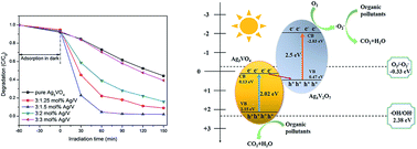
Novel direct Z-scheme Ag3VO4/Ag4V2O7 composites were synthesized by one-step hydrothermal method for the first time. The photocatalytic performance was evaluated by the degradation of methylene blue (MB) and phenol under visible light irradiation (λ ≥ 420 nm). The results showed that the as-synthesized heterojunctions can significantly enhance photocatalytic activity in comparison with pure Ag3VO4. The optimum photocatalytic efficiency of 3[thin space (1/6-em)]:[thin space (1/6-em)]1.5 mol% Ag/V sample for the degradation MB and phenol reached up to about 100% and 62.1%, respectively. In addition, 3[thin space (1/6-em)]:[thin space (1/6-em)]1.25 mol% Ag/V sample had an excellent visible light response range, which occurred around 652 nm. Based on the photocurrent and the radical-trapping experiments, the possible for the enhancing photocatalytic mechanism was found to be a direct Z-scheme heterojunction system, which not only can improve the photogenerated electron–hole pairs' separation but also exhibit strong oxidation and reduction ability.

1. Introduction

With the rapid development of industry, fossil fuels, such as coal, oil and gas, have been exploited and utilized excessively, which has caused serious environmental pollution and an energy crisis.1,2 The exploitation of pollution-free techniques for environment remediation is an urgent task for sustainable development.3,4 Semiconductor photocatalysis has been considered as a promising and environmentally friendly technology to degrade organic pollutants with solar energy, and has attracted tremendous attention.5–8 As is known, traditional single-component photocatalyst has poor quantum efficiency and low photocatalytic performance because the photogenerated electrons and holes can easily recombine each other.9 In the past few decades, various strategies had been proposed to design and fabricate highly efficient photocatalysts.10–14 Among them, the use of heterojunction-type photocatalyst, which can take full of advantages of each component, is an important strategy to overcome those drawbacks because it can efficiently improve the photogeneraterd electron–hole separation.15–18 Unfortunately, this improvement on charge separation is at the cost of weakening the redox ability, because the photogeneraterd electrons and holes are concentrated on the band with lower redox potentials.19 This is not favourable for the photocatalytic process requiring high redox ability.14,20

In recently, the construction of artificial Z-scheme photocatalytic system is an ideal and effective means because it not only can reduce the bulk electron–hole recombination, but also can preserve excellent redox ability.21,22 Actually, it has the same band alignment with typical heterojunction, but exhibits an opposite direction of charge transfer. The photogeneraterd electrons on the semiconductor with lower conduction band potential will combine with the holes on another semiconductor with higher valence band potential, and the electrons and holes with stronger redox ability remain on two semiconductors. However, the majority of the synthesized artificial Z-scheme photocatalytic systems usually had noble metal (Ag, Au)23–25 or redox mediators (Fe3+/Fe2+, IO3−/I),26,27 which led to lower optical absorption or existed a reversible reaction, respectively. And these results will bring about great difficulties to their practical application. Recently, the direct Z-scheme system attracts increasingly interest because the above problems can be solved well by this system.28–30 The different charge carrier transfers path of typical heterojunction and Z-scheme heterojunction are depicted in Fig. 1.


image file: c6ra22150e-f1.tif
Fig. 1 Scheme illustration of the different charge carrier transfer path of (a) typical heterojunction and (b) direct Z-scheme heterojunction.

As a kind of excellent inorganic antibacterial agent, Ag-based materials has been widely applied in many fields.31–34 Meanwhile, they were deemed to important semiconductor photocatalysts.35–40 Among the Ag-containing photocatalysts, the monoclinic scheelite Ag3VO4 has attracted much interest due to its special band structures and a narrow band gap (about 1.9–2.2 eV).41,42 However, the activity of pure Ag3VO4 is still low and needs to be modified.43,44 As one of the effective methods for enhancing photocatalytic performance for Ag3VO4, constructing heterojunction has been widely used.15,45,46 Many researchers have used this method to improve the photocatalytic activity of Ag3VO4. Wang et al. have investigated the catalytic performance of the g-C3N4/Ag3VO4 heterostructure, finding that the coupled semiconductor exhibited higher photoactivity for triphenylmethane dye degradation than that of the single semiconductor under visible light irradiation.47 Akbarzadeh et al. have successfully prepared the Ag3VO4/Ag3PO4/Ag heterojunction photocatalyst, which showed higher photocatalytic activity than Ag3VO4/Ag3PO4 and pure Ag3VO4.8 In addition, TiO2/Ag3VO4,1,48 Co3O4/Ag3VO4 45 and ZnFe2O4/Ag3VO4 46 have been developed with enhancing photocatalytic efficiency in visible light irradiation compared to the individual photocatalyst. As far as we know, the direct Z-scheme Ag3VO4-based heterojunction photocatalysts are not be reported. Based on the advantages of above-mentioned direct Z-scheme system, it is very necessary to construct direct Z-scheme heterojunction system. As another Ag-based narrow band gap semiconductor, the band gap of Ag4V2O7 is about 2.5 eV, and the conduction band (CB) of it has much better reducibility than the CB of Ag3VO4 due to the more negative potential of the CB for Ag4V2O7.49,50 Therefore, it is very likely that constructing the direct Z-scheme Ag3VO4/Ag4V2O7 system should be able to enhance photocatalytic performance remarkably.

Herein, we for the first time fabricated the direct Z-scheme Ag3VO4/Ag4V2O7 heterojunction photocatalysts by one-step hydrothermal method. The photocatalytic performance was evaluated by the degradation of methylene blue (MB) and phenol under visible light irradiation (λ ≥ 420 nm). The results showed that the as-synthesized heterojunctions can significantly enhance photocatalytic activity in comparison with pure Ag3VO4. The optimum photocatalytic efficiency of 3[thin space (1/6-em)]:[thin space (1/6-em)]1.5 mol% Ag/V sample for the degradation MB and phenol reached up to about 100% and 62.1%, respectively. In addition, 3[thin space (1/6-em)]:[thin space (1/6-em)]1.25 mol% Ag/V sample had an excellent visible light response range, which occurred around 652 nm. Based on the photocurrent and the radical-trapping experiments, the possible for the enhancing photocatalytic mechanism was found to be a direct Z-scheme heterojunction system, which not only can improve the photogenerated electron–hole pairs' separation but also exhibit strong oxidation and reduction ability.

2. Experimental

2.1 Synthesis of Ag3VO4/Ag4V2O7 composite photocatalysts

All the chemicals and solvents were of analytical reagent grade and were used without further purification. The Ag3VO4/Ag4V2O7 composite photocatalysts were prepared via one-step hydrothermal method. The details were as follows: the molar ratio of silver to vanadium (Ag to V) used were 3[thin space (1/6-em)]:[thin space (1/6-em)]1.25, 3[thin space (1/6-em)]:[thin space (1/6-em)]1.5, 3[thin space (1/6-em)]:[thin space (1/6-em)]2, 3[thin space (1/6-em)]:[thin space (1/6-em)]3, respectively. 3 mmol AgNO3 was dissolved in 30 mL of deionized water, corresponding molar NaVO3 was dissolved in 30 mL of distilled water, which was heated at 60 °C with stirring for 10 min to form transparent solution. The as-prepared AgNO3 solution was added dropwise to NaVO3 solution under vigorous stirring for 30 min to obtain an orange-yellow slurry. Then, 4 mol L−1 (M) NaOH was dropwise in the upper slurry to adjust the pH value of 11. After the mixture was stirred for about 10 min, the obtained precursor was transferred into a 100 mL Teflon-lined stainless autoclave at 140 °C for 8 h. Lastly, the products were cooled to room temperature naturally, and collected by centrifugation, washed with Milli-Q water several times to ensure that the residual impurities were removed, and dried at 80 °C for 10 h.

For comparison, pure Ag3VO4 was also prepared via the described method, but applying a molar ratio of 3[thin space (1/6-em)]:[thin space (1/6-em)]1 for Ag/V.

2.2 Characterization

The crystalline phases of pure Ag3VO4 and Ag3VO4/Ag4V2O7 were determined by using X-ray diffraction (XRD) (D/MAX-RB, Rigaku, Japan). The diffraction patterns were recorded in the 20–70° range with a Cu Kα source (λ = 0.15405) running at 40 kV and 30 mA. The morphologies of the as-prepared samples were measured by using scanning electron microscopy (SEM, S-4800, Hitachi, Japan). The transmission electron microscopy (TEM) and the high-resolution transmission electron microscopy (HRTEM) images were obtained with a transmission electron microscope (F-20, FEI, USA) at an accelerating voltage of 200 kV. X-ray photoelectron spectroscopy (XPS) was performed on an X-ray photoelectron spectrometer (ESCALAB 250Xi) using Al Kα radiation. The UV-vis diffuse reflectance spectra (DRS) of the photocatalysts were recorded in air at room temperature in the wavelength range of 300–800 nm using a UV-vis spectrophotometer (U-3900H, Hitachi, Japan) equipped with an integrating sphere.

2.3 Photocatalytic experiments

The photocatalytic activities of the as-prepared samples were evaluated by the degradation of methylene blue (MB) with an initial dye concentration of 25 mg L−1 at 664 nm and phenol with an initial concentration of 40 mg L−1 at 270 nm under visible light irradiation (λ ≥ 420 nm, 400 W Xe lamp). In each experiment, 30 mg of the as-prepared samples were respectively dispersed in 30 mL of MB solution and 30 mL of phenol solution followed by stirring for 60 min in the dark to achieve adsorption–desorption equilibrium before light irradiation. During the irradiation, 3 mL suspensions from each reaction sample were collected at 30 min (60 min for phenol degradation) intervals and centrifuged to remove the photocatalyst particles. Finally, the centrifuged solution was checked absorbance spectrum using a UV-vis spectrophotometer (U-3900H, Hitachi, Japan) at 664 nm and 270 nm, respectively. The ratio (C/C0) of the MB and phenol concentrations were adopted to evaluate the degradation efficiency, where C0 was the initial concentration and C was the concentration at certain time.

2.4 Photocurrent measurements

The measurements of the photocurrent were carried out on an electrochemical workstation (5060F, RST, China) in a standard three-electrode system in which the samples, an Ag/AgCl electrode (saturated KCl) and a Pt wire were used as the working electrode, reference electrode and counter electrode, respectively. 0.5 M Na2SO4 aqueous solution was introduced as the electrolyte. A 100 W incandescent lamp with a 420 nm cut-off filter was used as the light source. For the preparation of the working electrode, 3 mg of the samples were dispersed in a certain amount of ethanol and Nafion solution homogeneously. The as-prepared samples were spread into a circle with a diameter of 6 mm on the bottom middle of an ITO glass substrate. The photocurrents of the photocatalysts when the light was switched on and off were measured at 0.8 V.

3. Result and discussion

3.1 XRD analysis

The crystallographic structure of as-prepared pure Ag3VO4 and Ag3VO4/Ag4V2O7 composite photocatalysts were detected by XRD analysis. Fig. 2 exhibits the XRD diffraction patterns of the pure Ag3VO4 and Ag3VO4/Ag4V2O7 composite photocatalysts. The diffraction peaks of Ag3VO4 can be well indexed into monoclinic Ag3VO4 (JCPDS card no. 43-0542). The main XRD peaks at 30.86°, 32.33°, 35.07°, 35.94°, 38.92° and 54.06° were well-matched with the crystal planes of (−1 2 1), (1 2 1), (3 0 1), (2 0 2), (0 2 2) and (3 3 1) of Ag3VO4. According to the ref. 49, it is difficult to prepare pure Ag4V2O7, because Ag4V2O7 often coexisted with Ag3VO4 in the synthesis. From Fig. 2, we can clearly found the diffraction peaks of Ag4V2O7 in Ag3VO4/Ag4V2O7 composites. The diffraction peaks of Ag4V2O7 can be well indexed into orthorhombic Ag4V2O7 (JCPDS card no. 77-0097). The main XRD peaks at 31.93°, 32.93°, 42.24°, 46.63° and 52.65° correspond to the crystal planes of (2 2 4), (0 4 0), (1 5 1), (1 1 7) and (1 3 7) of Ag4V2O7, respectively. Therefore, the diffraction peaks of Ag3VO4/Ag4V2O7 consisted of the characteristic peaks of Ag3VO4 (marked with ◆) and Ag4V2O7 (marked with ●), which implied that the co-existence of Ag3VO4 and Ag4V2O7 in the as-prepared Ag3VO4/Ag4V2O7 composites. No signals for other crystalline phases were detected in the composite photocatalysts.
image file: c6ra22150e-f2.tif
Fig. 2 XRD patterns of as-prepared pure Ag3VO4 and different molar ratio of Ag/V samples.

3.2 Morphology characterization

The morphology of pure Ag3VO4 and Ag3VO4/Ag4V2O7 composites was observed by SEM. Fig. 3 shows the SEM images of (a) pure Ag3VO4, (b) 3[thin space (1/6-em)]:[thin space (1/6-em)]1.25 mol% Ag/V, (c) 3[thin space (1/6-em)]:[thin space (1/6-em)]1.5 mol% Ag/V, (d) 3[thin space (1/6-em)]:[thin space (1/6-em)]2 mol% Ag/V, and (e) 3[thin space (1/6-em)]:[thin space (1/6-em)]3 mol% Ag/V. As shown in Fig. 3a, pure Ag3VO4 presented irregular ragged particles and the size ranged from 0.5 μm to 3 μm. Similar results were also observed in the other samples (Fig. 3b–e). The results of SEM indicated that the presence of Ag4V2O7 could not change the morphology of Ag3VO4 during the hydrothermal reaction.
image file: c6ra22150e-f3.tif
Fig. 3 SEM images of (a) pure Ag3VO4, (b) 3[thin space (1/6-em)]:[thin space (1/6-em)]1.25 mol% Ag/V, (c) 3[thin space (1/6-em)]:[thin space (1/6-em)]1.5 mol% Ag/V, (d) 3[thin space (1/6-em)]:[thin space (1/6-em)]2 mol% Ag/V, and (e) 3[thin space (1/6-em)]:[thin space (1/6-em)]3 mol% Ag/V.

To further testify the existence of heterojunction between Ag3VO4 and Ag4V2O7, we observed the composites by TEM and HRTEM. Fig. 4 shows the TEM images of (a) pure Ag3VO4 and (b) 3[thin space (1/6-em)]:[thin space (1/6-em)]1.5 mol% Ag/V and the HRTEM image of (c) 3[thin space (1/6-em)]:[thin space (1/6-em)]1.5 mol% Ag/V. As shown in Fig. 4a and b, the TEM images of samples revealed the irregular morphology, which were accordance with the SEM images. The interplanar spacings of 0.29 and 0.27 nm shown in Fig. 4c matched well with the (−1 2 1) and (0 4 0) lattice planes of the Ag3VO4 and Ag4V2O7, respectively. Thus the results were corresponding with the XRD, and the formed heterojunction maybe ensure the better transfer of charge carriers.


image file: c6ra22150e-f4.tif
Fig. 4 TEM images of (a) pure Ag3VO4 and (b) 3[thin space (1/6-em)]:[thin space (1/6-em)]1.5 mol% Ag/V and the HRTEM image of (c) 3[thin space (1/6-em)]:[thin space (1/6-em)]1.5 mol% Ag/V.

3.3 Chemical state analysis

The XPS analysis was used to further understand the chemical state of pure Ag3VO4 and 3[thin space (1/6-em)]:[thin space (1/6-em)]1.5 mol% Ag/V (Ag3VO4/Ag4V2O7) composite photocatalysts. Before the analysis, all peaks of the other elements were calibrated according to the deviation between the C 1s peak and the standard signal of C 1s at 284.8 eV.

The survey scan spectra XPS spectra of 3[thin space (1/6-em)]:[thin space (1/6-em)]1.5 mol% Ag/V (Ag3VO4/Ag4V2O7) display the characteristic peaks of Ag, V and O elements (Fig. 5a). Fig. 5b–d shows the high-resolution XPS spectra of Ag 3d, V 2p and O 1s for pure Ag3VO4 and 3[thin space (1/6-em)]:[thin space (1/6-em)]1.5 mol% Ag/V. The binding energy located at 368.24 eV and 374.21 eV were attributable to Ag 3d5/2 and Ag 3d3/2, respectively, which can be ascribed to Ag+ ions of pure Ag3VO4 (Fig. 5b).7 Besides, the binding energy of Ag 3d5/2 and Ag 3d3/2 for 3[thin space (1/6-em)]:[thin space (1/6-em)]1.5 mol% Ag/V were 368.19 eV and 374.16 eV, respectively, both of which had a shift of 0.05 eV to low energy region compared with the pure Ag3VO4.51 The result appeared to suggest the existence of covalent bonding between the oxygen and the silver ions in Ag3VO4 and Ag4V2O7.51 No obvious characteristic diffraction peaks of Ag0 (located at 368.6 eV and 374.7 eV)52 and silver oxides (367.5 eV and 373.5 eV)53 were detected in above composites, which well-matched with the XRD results.


image file: c6ra22150e-f5.tif
Fig. 5 High resolution X-ray photoelectron spectroscopy (XPS) spectra: (a) overall spectra of 3[thin space (1/6-em)]:[thin space (1/6-em)]1.5 mol% Ag/V; (b) Ag 3d; (c) V 2p; (d) O 1s.

Fig. 5c shows that two peaks at 516.84 and 524.33 eV were separately attributed to V 2p5/2 and V 2p3/2 of V5+ ions of pure Ag3VO4.54 In addition, the binding energy of V 2p5/2 and V 2p3/2 for 3[thin space (1/6-em)]:[thin space (1/6-em)]1.5 mol% Ag/V were 516.75 eV and 524.23 eV,54 respectively, which had a shift of 0.09 eV and 0.10 eV compared with the pure Ag3VO4. The result indicated the existence of covalent bonding between the vanadium and the oxygen in the form of (VO4)3− and (V2O7)4−.51

The peaks for O 1s located at 530.07 eV corresponded to the O2− anion (Fig. 5d). Compared with pure Ag3VO4, the signal of O 1s for 3[thin space (1/6-em)]:[thin space (1/6-em)]1.5 mol% Ag/V had a 0.05 eV shift to lower binding energy. The banding energy of O 1s could be attributed to the surface lattice oxygen and adsorbed oxygen species, respectively.48

These results demonstrated the interaction between Ag3VO4 and Ag4V2O7, confirming the existence of chemical bonds between Ag3VO4 and Ag4V2O7 in the composites.

3.4 Optical properties

The optical properties of pure Ag3VO4 and Ag3VO4/Ag4V2O7 composites were investigated using the UV-vis diffuse reflectance spectroscopy (Fig. 6). As illustrated in Fig. 6, all samples showed an absorbance in the visible light absorption ability. An obvious red shift of the optical absorption edge was observed for the composites. The onset of visible light absorption by 3[thin space (1/6-em)]:[thin space (1/6-em)]1.25 mol% Ag/V even occurred around 652 nm, which indicated that Ag3VO4/Ag4V2O7 composites had an excellent visible light response range. The optical band gap for the semiconductor photocatalysts was estimated using the following equation:
image file: c6ra22150e-t1.tif
where λ is the maximum wavelength of absorption by photocatalysts (nm) (illustrated by the dash line in Fig. 6), and Eg is the estimated band gap energy of the photocatalysts (eV). As shown in Fig. 6, the onset wavelength for pure Ag3VO4, 3[thin space (1/6-em)]:[thin space (1/6-em)]1.25 mol% Ag/V, 3[thin space (1/6-em)]:[thin space (1/6-em)]1.5 mol% Ag/V, 3[thin space (1/6-em)]:[thin space (1/6-em)]2 mol% Ag/V and 3[thin space (1/6-em)]:[thin space (1/6-em)]3 mol% Ag/V occurred around 613, 652, 642, 635 and 629 nm, respectively. On the basis of the above equation and the onset wavelength, the calculated band gaps of samples were 2.02, 1.90, 1.93, 1.95 and 1.97 eV, respectively. These results indicated that the Ag3VO4/Ag4V2O7 composites could not only better absorption visible light but also broaden the light response range.

image file: c6ra22150e-f6.tif
Fig. 6 UV-vis DRS spectra of pure Ag3VO4, 3[thin space (1/6-em)]:[thin space (1/6-em)]1.25 mol% Ag/V, 3[thin space (1/6-em)]:[thin space (1/6-em)]1.5 mol% Ag/V, 3[thin space (1/6-em)]:[thin space (1/6-em)]2 mol% Ag/V, 3[thin space (1/6-em)]:[thin space (1/6-em)]3 mol% Ag/V.

3.5 Photocatalytic properties

The photocatalytic performance of as-prepared pure Ag3VO4 and Ag3VO4/Ag4V2O7 composites were evaluated by decomposing MB2,55,56 under visible light irradiation (λ ≥ 420 nm) (Fig. 7). The adsorption ratio was recorded when adsorption–desorption equilibrium was achieved before irradiation. As shown in Fig. 7, the tiny changes of adsorption in dark indicated that the degradation of MB was mainly affected by visible light irradiation rather than surface adsorption.
image file: c6ra22150e-f7.tif
Fig. 7 Photocatalytic activity of pure Ag3VO4 and Ag3VO4/Ag4V2O7 composites for the degradation of MB under the visible light irradiation (λ ≥ 420 nm).

From Fig. 7, it can be seen that the Ag3VO4/Ag4V2O7 composites was obviously higher than that of the pure Ag3VO4 samples, and the best activity was obtained for 3[thin space (1/6-em)]:[thin space (1/6-em)]1.5 mol% Ag/V. At reaching 30 min, the photodegradation rate of MB reached up to 87.1% for 3[thin space (1/6-em)]:[thin space (1/6-em)]1.5 mol% Ag/V. After 150 min of irradiation, it almost reached up to 100% which was about 1.79 times than pure Ag3VO4 (55.76%), while the 3[thin space (1/6-em)]:[thin space (1/6-em)]1.25 mol%, 3[thin space (1/6-em)]:[thin space (1/6-em)]2 mol% and 3[thin space (1/6-em)]:[thin space (1/6-em)]3 mol% samples reached rates of up to 90.9%, 84.0% and 60.7%, respectively. This observation implied that the heterojunction formed between Ag3VO4 and Ag4V2O7 played an important role in improving the photocatalytic activity.

Moreover, Fig. 7 also demonstrates that the degradation rate of MB using the Ag3VO4/Ag4V2O7 composites initially increased along with the increase of the vanadium content in the order of 3[thin space (1/6-em)]:[thin space (1/6-em)]1.25 mol% and 3[thin space (1/6-em)]:[thin space (1/6-em)]1.5 mol% at the beginning of irradiation. Whereas the degradation ratio of MB decreased when the mole ratio of Ag/V were 3[thin space (1/6-em)]:[thin space (1/6-em)]2 and 3[thin space (1/6-em)]:[thin space (1/6-em)]3. The plausible reason for the result in this finding can be explained by the following aspects. With the increase of the amount of vanadium, the proportion of Ag3VO4 decreased along with increasing Ag4V2O7. Excess Ag4V2O7 might act as recombination centers of the photogenerated electron–hole pairs. In addition, extra Ag4V2O7 could lead to the reduction in active center sites of photocatalysts.

Furthermore, circulating runs in the photocatalytic degradation of MB were performed under visible light irradiation to check the stability of the best photocatalyst (3[thin space (1/6-em)]:[thin space (1/6-em)]1.5 mol% Ag/V). As shown in Fig. 8, the photocatalyst did not display any significant loss of photocatalytic performance. This result implied that the Ag3VO4/Ag4V2O7 photocatalysts are not photo-corroded during the photodegradation of the pollutant molecules, which is particularly important for their application.


image file: c6ra22150e-f8.tif
Fig. 8 Circulating runs in the photocatalytic degradation of MB in the presence of the 3[thin space (1/6-em)]:[thin space (1/6-em)]1.5 mol% Ag/V sample under visible light irradiation.

In addition to MB, phenol, a typical colorless contaminant, was also chosen to further evaluate the photocatalytic performance of the samples. There was tiny adsorption of phenol after 60 min of stirring in the dark and the photodegradation rate of phenol for pure Ag3VO4 and 3[thin space (1/6-em)]:[thin space (1/6-em)]1.5 mol% Ag/V are shown in Fig. 9.


image file: c6ra22150e-f9.tif
Fig. 9 Degradation ratio of phenol using pure Ag3VO4 and 3[thin space (1/6-em)]:[thin space (1/6-em)]1.5 mol% Ag/V under visible light irradiation.

The results indicated that phenol could be hardly degraded under visible light irradiation without photocatalysts. After 300 min of irradiation, the degradation rate of phenol for 3[thin space (1/6-em)]:[thin space (1/6-em)]1.5 mol% Ag/V (62.1%) was 1.83 times than pure Ag3VO4 (33.9%). Fig. 10a and b show the temporal absorption spectral changes of phenol in photodegradation for pure Ag3VO4 and 3[thin space (1/6-em)]:[thin space (1/6-em)]1.5 mol% Ag/V under visible light irradiation. Although an obvious absorption peak at 270 nm could be observed after irradiation for 300 min, the absorption peak at 270 nm was much declined for 3[thin space (1/6-em)]:[thin space (1/6-em)]1.5 mol% Ag/V as shown in Fig. 10b, compared to pure Ag3VO4. These findings further confirmed the enhanced photocatalytic activity of the Ag3VO4/Ag4V2O7 composites.


image file: c6ra22150e-f10.tif
Fig. 10 Time-dependent UV-vis absorption spectra of phenol in the presence of various photocatalysts: (a) pure Ag3VO4 and (b) 3[thin space (1/6-em)]:[thin space (1/6-em)]1.5 mol% Ag/V.

3.6 Photocurrent measurements

On the basis of the experimental results above, it is believed that the formed heterojunctions play a key hole in reducing the recombination rate of electrons and holes. To better confirm this assumption, we investigated its photocurrent responses in an electrolyte under visible light, which may indirectly correlate with the generation and transfer of the photoinduced charge carriers in the photocatalytic process. Fig. 11 shows the photocurrent response of pure Ag3VO4 and the 3[thin space (1/6-em)]:[thin space (1/6-em)]1.5 mol% Ag/V sample when the light was switched on and off. Remarkably, the current abruptly increased and decreased when the light source was switched on and off. The 3[thin space (1/6-em)]:[thin space (1/6-em)]1.5 mol% Ag/V sample exhibited an obviously enhanced photocurrent response compared with pure Ag3VO4. This implies that more efficient separation of the photogenerated electron–hole pairs and fast transfer of photoinduced charge carriers occurred in the 3[thin space (1/6-em)]:[thin space (1/6-em)]1.5 mol% Ag/V photocatalyst, which could be attributed to close interfacial connections and the synergetic effect existing between Ag3VO4 and Ag4V2O7. Meanwhile, the results are well corresponded to their photocatalytic performance.
image file: c6ra22150e-f11.tif
Fig. 11 Photocurrent responses of pure Ag3VO4 and the 3[thin space (1/6-em)]:[thin space (1/6-em)]1.5 mol% Ag/V sample under visible light irradiation.

3.7 Photocatalytic mechanism

To further explore the effect of these active species during the photocatalytic degradation process, radical-trapping experiments with different scavengers were performance with the 3[thin space (1/6-em)]:[thin space (1/6-em)]1.5 mol% Ag/V as shown in Fig. 12. In this way, active species including holes (h+), superoxide radicals (˙O2) and hydroxyl radicals (˙OH) with effective oxidation and reduction potentials could be determined. In this study, 1 mM benzoquinone (BQ, a scavenger of ˙O2), 1 mM sodium oxalate (Na2C2O4, a scavenger of h+) and 1 mM isopropanol (IPA, a scavenger of ˙OH) were adopted. Fig. 12 shows the variation of MB degradation with different scavenger added. As shown in Fig. 12, reaction rate constant k was decreased with the addition of IPA. Actually, the degradation efficiency of MB changed very slightly after 150 min of irradiation from the inset in Fig. 12, compared to no scavenger. This result indicated that ˙OH radicals were not the dominant active species in the photocatalytic reaction system of Ag3VO4/Ag4V2O7. After addition of Na2C2O4, the degradation efficiency of MB was remarkably depressed, which suggested that h+ was an important active species in the MB photocatalytic degradation. In addition, when BQ was added into the reaction system, the degradation efficiency of MB was almost completely depressed, whose apparent reaction rate constant k was decelerated obviously from 2.53 × 10⁻² to 2.85 × 10⁻³ min−1. Considering the above results, h+ and ˙O2 were main active species in the degradation process, and ˙O2 was acted as the dominant active species responsible for MB degradation under visible light irradiation.
image file: c6ra22150e-f12.tif
Fig. 12 Effects of different scavengers on the degradation of MB in the presence of 3[thin space (1/6-em)]:[thin space (1/6-em)]1.5 mol% Ag/V composite under visible light irradiation (λ ≥ 420 nm).

A possible mechanism for the MB photodegradation of the enhanced activity of the Ag3VO4/Ag4V2O7 composites under visible-light irradiation could be proposed. The conduction band (CB) and valence band (VB) potentials of a semiconductor can be calculated by the following equation:57

 
image file: c6ra22150e-t2.tif(1)
 
EVB = ECB + Eg (2)
where χ is the absolute electronegativity of the semiconductor, which is the geometric mean of the electronegativity of the constituent atoms. Ee is the energy of free electrons in the hydrogen scale (about 4.5 eV), Eg is the band gap energy of the semiconductor. The χ value of Ag3VO4 is 5.64 eV 58 and the band gap energy of Ag3VO4 is 2.02 eV. According to the above equations, the ECB value of Ag3VO4 was 0.13 eV, and the homologous EVB value was 2.15 eV. According to the ref. 49, the band gap energy, the ECB value and the EVB value for Ag4V2O7 were 2.5, −2.03 and 0.47 eV, respectively.

Thus, the photogenerated electrons on the CB of Ag4V2O7 can react with O2 to form ˙O2 radicals due to the position of CB (−2.03 eV vs. NHE) of Ag4V2O7 is more negative than the potential of O2/˙O2 (−0.33 eV vs. NHE).49 Whereas, the VB potential (0.47 eV vs. NHE) of Ag4V2O7 is lower than the standard redox potential of OH, H2O/˙OH (2.38 eV vs. NHE), implying that the photogenerated holes in the VB of Ag4V2O7 cannot oxidize the adsorbed H2O or OH to generate ˙OH.49 As for Ag3VO4, the photogenerated electrons on the CB of Ag3VO4 cannot react with O2 to form ˙O2 radicals because the position of CB (0.13 eV vs. NHE) of Ag3VO4 is less negative than the potentials of O2/˙O2 (−0.33 eV vs. NHE). The VB potential (2.15 eV vs. NHE) of Ag3VO4 is lower than the standard redox potential of OH, H2O/˙OH (2.38 eV vs. NHE), suggests that the photogenerated holes in the VB of Ag3VO4 also cannot oxidize the adsorbed H2O or OH to generate ˙OH. The findings are corresponding to the results of the active species trapping experiments.

On the basis of the above experiment results, a novel direct Z-scheme mechanism for the enhanced photocatalytic performance of Ag3VO4/Ag4V2O7 heterojunctions was proposed. As illustrated in Fig. 13, both Ag3VO4 and Ag4V2O7 can be initiated by the visible-light to yield photogenerated electron–hole pairs. If the charge transfer path of photogenerated electron–hole pairs is like the typical heterojunction system, then the photogenerated electrons in the CB of Ag3VO4 will generate fewer ˙O2 radicals because of its low reducibility. Thus, the photogenerated electrons in the CB of Ag3VO4 tend to transfer and recombine with the photogenerated holes in the VB of Ag4V2O7. In this way, the more photogenerated electrons accumulated in the CB of Ag4V2O7 can reduce the adsorbed O2 to form more ˙O2, which is a powerful oxidative specie can break down the chromophores of organic pollutants into small molecules, e.g. CO2 and H2O. Meanwhile, the photogenerated holes left behind in the VB of Ag3VO4 can directly oxidize organic pollutants. Therefore, it can draw a conclusion that the photocatalytic reaction of prepared Ag3VO4/Ag4V2O7 heterojunctions followed a direct Z-scheme mechanism, which could improve the photogenerated electron–hole pairs' separation and transfer as well as show a strong oxidation and reduction ability for efficiency degradation of organic pollutants.


image file: c6ra22150e-f13.tif
Fig. 13 The possible photocatalytic mechanism of Ag3VO4/Ag4V2O7 heterojunction photocatalysts for degradation of organic pollutants under visible light irradiation.

4. Conclusions

In summary, we have firstly constructed the direct Z-scheme Ag3VO4/Ag4V2O7 heterojunction photocatalysts by one-step hydrothermal method. Characterization tests indicated that the as-prepared photocatalysts had stable visible-light-driven photocatalytic performance and high efficiency. The Ag3VO4/Ag4V2O7 composites had an excellent visible light response range, which occurred around 652 nm. Moreover, the molar ratio at 3[thin space (1/6-em)]:[thin space (1/6-em)]1.5 of the Ag/V sample performed optical photocatalytic properties for degradation of MB (∼100%) and phenol (∼62.1%). Hence, the enhancing photocatalytic activity was due to the formation of a direct Z-scheme heterojunction between the Ag3VO4 and Ag4V2O7, which not only resulted in the electrons in the CB of Ag4V2O7 exhibits high reducibility and the holes in the VB of Ag3VO4 shows high oxidizability, but also improve the photogenerated electron–hole pairs' separation.

Acknowledgements

We gratefully acknowledge the financial support provided by the National Natural Science Foundation of China (Grant No. 21271022).

References

  1. J. X. Wang, H. Ruan, W. J. Li, D. Z. Li, Y. Hu, J. Chen, Y. Shao and Y. Zheng, J. Phys. Chem. C, 2012, 116, 13935–13943 CAS.
  2. D. F. Xu, B. Cheng, S. W. Cao and J. G. Yu, Appl. Catal., B, 2015, 164, 380–388 CrossRef CAS.
  3. F. Z. Wang, W. J. Li, S. N. Gu, H. D. Li, H. L. Zhou and X. Wu, RSC Adv., 2015, 5, 89940–89950 RSC.
  4. J. G. Hou, Z. Wang, C. Yang, W. L. Zhou, S. Q. Jiao and H. G. Zhu, J. Phys. Chem. C, 2013, 117, 5132–5141 CAS.
  5. H. D. Li, W. J. Li, S. N. Gu, F. Z. Wang, H. L. Zhou, X. T. Liu and C. J. Ren, RSC Adv., 2016, 6, 48089–48098 RSC.
  6. G. Wang, Y. Ren, G. J. Zhou, J. P. Wang, H. F. Cheng, Z. Y. Wang, J. Zhan, B. B. Huang and M. H. Jiang, Surf. Coat. Technol., 2013, 228, S283–S286 CrossRef CAS.
  7. D. P. Das, A. Samal, J. Das, A. Dash and H. Gupta, Photochem. Photobiol., 2014, 90, 57–65 CrossRef CAS PubMed.
  8. E. Akbarzadeh, S. R. Setayesh and M. R. Gholami, RSC Adv., 2016, 6, 14909–14915 RSC.
  9. F. Le Formal, S. R. Pendlebury, M. Cornuz, S. D. Tilley, M. Grätzel and J. R. Durrant, J. Am. Chem. Soc., 2014, 136, 2564–2574 CrossRef CAS PubMed.
  10. S. G. Kumar and L. G. Devi, J. Phys. Chem. A, 2011, 115, 13211 CrossRef CAS PubMed.
  11. Y. Li, Y. Jiang, S. Peng and F. Jiang, J. Hazard. Mater., 2010, 182, 90 CrossRef CAS PubMed.
  12. X. Zhang and Q. Liu, Appl. Surf. Sci., 2008, 254, 4780 CrossRef CAS.
  13. D. E. Huang, S. Liao, S. Quan, L. Liu, Z. He, J. Wan and W. Zhou, J. Mater. Res., 2007, 22, 2389 CrossRef CAS.
  14. Z. Liu, X. Zhang, S. Nishimoto, M. Jin, D. A. Tryk, T. Murakami and A. Fujishima, Langmuir, 2007, 23, 10916 CrossRef CAS PubMed.
  15. H. L. Wang, L. S. Zhang, Z. G. Chen, J. Q. Hu, S. J. Li, Z. H. Wang, J. S. Liu and X. C. Wang, Chem. Soc. Rev., 2014, 43, 5234–5244 RSC.
  16. M. Ge, Y. F. Li, L. Liu, Z. Zhou and W. Chen, J. Phys. Chem. C, 2011, 115, 5220–5225 CAS.
  17. Y. Hou, F. Zuo, A. Dagg and P. Y. Feng, Nano Lett., 2012, 12, 6464–6473 CrossRef CAS PubMed.
  18. Y. J. Wang, Q. S. Wang, X. Y. Zhan, F. M. Wang, M. Safdar and J. He, Nanoscale, 2013, 5, 8326–8339 RSC.
  19. P. Zhou, J. G. Yu and M. Jaroniec, Adv. Mater., 2014, 26, 4920–4935 CrossRef CAS PubMed.
  20. H. Y. Li, Y. J. Sun, B. Cai, S. Y. Gan, D. X. Han, L. Niu and T. S. Wu, Appl. Catal., B, 2015, 170, 206–214 CrossRef.
  21. P. Zhou, J. G. Yu and M. Jaroniec, Adv. Mater., 2014, 26, 4920–4935 CrossRef CAS PubMed.
  22. H. J. Li, W. G. Tu, Y. Zhou and Z. G. Zou, Adv. Sci., 2016, 1500389 Search PubMed.
  23. X. F. Wang, S. F. Li, Y. Q. Ma, H. G. Yu and J. G. Yu, J. Phys. Chem. C, 2011, 115, 14648–14655 CAS.
  24. L. Q. Ye, J. Y. Liu, C. Q. Gong, L. H. Tian, T. Y. Peng and L. Zan, ACS Catal., 2012, 2, 1677–1683 CrossRef CAS.
  25. Y. Sasaki, H. Kato and A. Kudo, J. Am. Chem. Soc., 2013, 135, 5441–5449 CrossRef CAS PubMed.
  26. K. Maeda, D. L. Lu and K. Domen, ACS Catal., 2013, 3, 1026–1033 CrossRef CAS.
  27. Y. Sasaki, A. Iwase, H. Kato and A. Kudo, J. Catal., 2008, 259, 133–137 CrossRef CAS.
  28. J. G. Yu, S. H. Wang, J. X. Low and W. Xiao, Phys. Chem. Chem. Phys., 2013, 15, 16883–16890 RSC.
  29. T. Y. Wang, W. Quan, D. L. Jiang, L. L. Chen, D. Li, S. C. Meng and M. Chen, Chem. Eng. J., 2016, 300, 280–290 CrossRef CAS.
  30. X. Jia, M. Tahir, L. Pan, Z. F. Huang, X. W. Zhang, L. Wang and J. J. Zou, Appl. Catal., B, 2016, 198, 154–161 CrossRef CAS.
  31. R. D. Holtz, B. A. Lima, A. G. Souza Filho, M. Brocchi and O. L. Alves, Nanomedicine: Nanotechnology, Biology and Medicine, 2012, 8, 935–940 CrossRef CAS PubMed.
  32. K. Naddafi, H. Jabbari and M. Chehrehei, Iran. J. Environ. Health Sci. Eng., 2010, 7, 223–228 CAS.
  33. B. S. Atiyeh, M. Costagliola, S. N. Hayek and S. A. Dibo, Burns, 2007, 33, 139–148 CrossRef PubMed.
  34. O. Choi, K. K. Deng, N. J. Kim, L. Ross, R. Y. Surampalli and Z. Hu, Water Res., 2008, 42, 3066–3074 CrossRef CAS PubMed.
  35. P. Wang, B. B. Huang, X. Y. Qin, X. Y. Zhang, Y. Dai, J. Y. Wei and M. H. Whangbo, Angew. Chem., Int. Ed., 2008, 47, 7931–7933 CrossRef CAS PubMed.
  36. P. Wang, B. B. Huang, X. Y. Zhang, X. Y. Qin, H. Jin, Y. Dai, Z. Y. Wang, J. Y. Wei, J. Zhan, S. Y. Wang, J. P. Wang and M. H. Whangbo, Chem.–Eur. J., 2009, 15, 1821–1824 CrossRef CAS PubMed.
  37. C. Hu, T. W. Peng, X. X. Hu, Y. L. Nie, X. F. Zhou, J. H. Qu and H. He, J. Am. Chem. Soc., 2010, 132, 857–862 CrossRef CAS PubMed.
  38. X. F. Wang, S. F. Li, H. G. Yu, J. G. Yu and S. W. Liu, Chem.–Eur. J., 2011, 17, 7777–7780 CrossRef CAS PubMed.
  39. C. W. Xu, Y. Y. Liu, B. B. Huang, H. Li, X. Y. Qin, X. Y. Zhang and Y. Dai, Appl. Surf. Sci., 2011, 257, 8732–8736 CrossRef CAS.
  40. P. S. Saud, Z. K. Ghouri, B. Pant, T. An, J. H. Lee, M. Park and H. Y. Kim, Carbon Lett., 2016, 18, 30–36 CrossRef.
  41. R. Konta, H. Kato, H. Kobayashi and A. Kudo, Phys. Chem. Chem. Phys., 2003, 5, 3061–3065 RSC.
  42. X. X. Hu, C. Hu and J. H. Qu, Mater. Res. Bull., 2008, 43, 2986–2997 CrossRef CAS.
  43. H. Xu, H. M. Li, G. S. Sun, J. X. Xia, C. D. Wu, Z. X. Ye and Q. Zhang, Chem. Eng. J., 2010, 160, 33–41 CrossRef CAS.
  44. C. M. Huang, K. W. Cheng, G. T. Pan, W. S. Chang and T. C. K. Yang, Chem. Eng. Sci., 2010, 65, 148–152 CrossRef CAS.
  45. L. Zhang, Y. M. He, P. Ye, Y. Wu, W. H. Qin and T. H. Wu, Mater. Sci. Eng., B, 2013, 178, 45–52 CrossRef CAS.
  46. L. Zhang, Y. M. He, P. Ye, Y. Wu and T. H. Wu, J. Alloys Compd., 2013, 549, 105–113 CrossRef CAS.
  47. S. M. Wang, D. L. Li, C. Sun, S. G. Yang, Y. Guan and H. He, Appl. Catal., B, 2014, 144, 885–892 CrossRef CAS.
  48. X. J. Zou, Y. Y. Dong, X. D. Zhang and Y. B. Cui, Appl. Surf. Sci., 2016, 366, 173–180 CrossRef CAS.
  49. J. X. Wang, X. Yang, J. Chen, J. J. Xian, S. G. Meng, Y. Zheng, Y. Shao and D. Z. Li, J. Am. Ceram. Soc., 2014, 97, 267–274 CrossRef CAS.
  50. C. M. Huang, G. T. Pan, Y. C. M. Li, M. H. Li and T. C. K. Yang, Appl. Catal., A, 2009, 358, 164–172 CrossRef CAS.
  51. K. S. Raju, M. K. P. Seydei and S. A. Suthanthiraraj, Mater. Lett., 1994, 19, 65–68 CrossRef CAS.
  52. C. Hu, T. W. Peng, X. X. Hu, Y. L. Nie, X. F. Zhou, J. H. Qu and H. He, J. Am. Chem. Soc., 2010, 132, 857–862 CrossRef CAS PubMed.
  53. H. S. Shin, H. C. Choi, Y. Jung, S. B. Kim, H. J. Song and H. J. Shin, Chem. Phys. Lett., 2004, 383, 418–422 CrossRef CAS.
  54. H. Xu, H. M. Li, L. Xu, C. D. Wu, G. S. Sun, Y. G. Xu and J. Y. Chu, Ind. Eng. Chem. Res., 2009, 48, 10771–10778 CrossRef CAS.
  55. X. H. Yang, H. T. Fu, X. Z. An, X. C. Jiang and A. B. Yu, RSC Adv., 2016, 6, 34103–34109 RSC.
  56. H. B. Rao, Z. W. Lu, X. Liu, H. W. Ge, Z. Y. Zhang, P. Zou, H. Hua and Y. Y. Wang, RSC Adv., 2016, 6, 46299–46307 RSC.
  57. S. N. Gu, W. J. Li, F. Z. Wang, S. Y. Wang, H. L. Zhou and H. D. Li, Appl. Catal., B, 2015, 170, 186–194 CrossRef.
  58. S. M. Wang, Y. Guan, L. P. Wang, W. Zhao, S. G. Yang, H. He and C. Sun, J. Comput. Theor. Nanosci., 2015, 12, 5016–5021 CrossRef.

This journal is © The Royal Society of Chemistry 2016