[Ir(ppy)2pyim]PF6 dielectric mixed with PMMA for area emission transistors†
Jing Li‡
a,
Wenhai Li‡a,
Dongxin Maa,
Weiqi Zhanga,
Lei Heb,
Lian Duana,
Liduo Wanga and
Guifang Dong*a
aKey Laboratory of Organic Optoelectronics and Molecular Engineering of Ministry of Education, Department of Chemistry, Tsinghua University, Beijing, 100084, P. R. China. E-mail: donggf@mail.tsinghua.edu.cn
bCollege of Chemistry and Chemical Engineering, Central South University, Changsha, Hunan Province 410083, P. R. China
First published on 27th September 2016
Abstract
We demonstrated an area emission transistor with [Ir(ppy)2pyim]PF6/PMMA as the dielectric layer. The brightness can be tuned by VDS and VGS, respectively. The device performance was optimized by adjusting the mass concentration ratios of PMMA. Different working mechanisms of the devices with and without PMMA were investigated through the Kelvin probe force microscope. The doping of PMMA will change the surface potential of [Ir(ppy)2pyim]PF6, and then change the properties of charge injection. Our research may open up a new way for the development of multifunctional devices.
Nowadays, with the expansive development of electronic devices, organic optoelectronic materials have attracted attention from all over the world by virtue of their various properties such as charge transport, light emission, chemical sensitivity, low cost and flexibility.1–10 Among them, iridium ionic complexes are widely used in organic light-emitting diodes (OLEDs) and light-emitting electrochemical cells (LECs), due to their high luminescent efficiency.11–14
Previously, based on an iridium ionic complex, [Ir(dmfpz)2(dtb-bpy)]PF6, we have proposed a novel kind of multifunctional device which had transistor characteristics and could give area light emission from dielectric layer.15 To prove the wide applicability of our approach and to understand the detailed working mechanism of the device, we carried on further research.
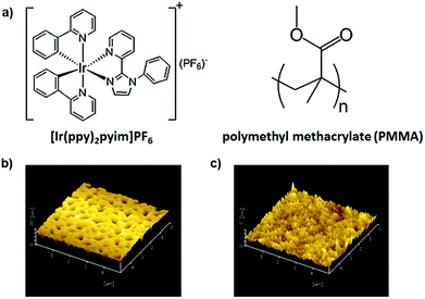
Here, we demonstrated related research on another iridium complex, [Ir(ppy)2pyim]PF6. By mixing this complex with different mass concentration ratios of polymethyl methacrylate (PMMA), we successfully optimized the device performance and achieved tunable area emission. Furthermore, the different working mechanisms of the devices with and without PMMA were explained with the help of the Kelvin probe force microscope (KPFM).16,17 Our study not only verified the great potential of iridium complex for multifunctional devices, but also suggested that the KPFM was a useful tool for mechanism analysis of optoelectronic devices. Fig. 1a depicts the chemical structure of [Ir(ppy)2pyim]PF6 and PMMA. [Ir(ppy)2pyim]PF6 was synthesized as published.18 Fig. 1b is the atomic force microscope (AFM) image of the film of pure [Ir(ppy)2pyim]PF6, from which a high density of pinholes can be found, and the film RMS roughness reaches 9.51 nm. The poor film-forming property of [Ir(ppy)2pyim]PF6 is due to the lack of alkyl groups in it, which can form steric hindrance to induce crystallization.15 The rough film and pinholes can increase leakage current and result in poor performance of device. Therefore, we employed PMMA to improve the film forming property.19,20 As shown in Fig. 1c, the film with PMMA turns smooth and homogeneous, with the RMS roughness reduced to only 0.71 nm.
Top-gate bottom-contact structured devices were fabricated using zinc tin oxide (ZTO) as the semiconductor and silver as the source/drain electrodes (Fig. 2a), the detailed fabrication procedures can be found in ESI.† To study the effect of mass concentration of PMMA on the device performance, different mass concentration ratios of PMMA (25%, 33% and 66%, marked as device A, B and C) were mixed with [Ir(ppy)2pyim]PF6. The relative dielectric constants of the mixed films were measured to be 2.88, 3.01 and 3.73 (Fig. S1†), and, under the same spin-coating condition, the thickness of these films were 130 nm, 200 nm and 250 nm.
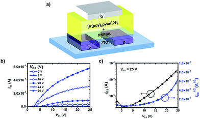 | ||
| Fig. 2 Device structure and transistor characteristics: (a) sketch of the devices; (b) the output curves of the device B; (c) the transfer curves of the device B. | ||
Fig. 2b and c are the output and transfer curves of the device B based on the mixed film with 33% mass concentration of PMMA, while Fig. S2a–d† shows the performance of the other two devices (A and C). All of the devices had typical n type transistor characteristics. Device B turned out to have the highest on/off current ratio of 250.
All the devices could give area emission from the dielectric layer, and the electroluminescent (EL) spectra peaks were at 552 nm (Fig. 3a), with the CIE coordinates of (0.44, 0.53). And the EL peak almost showed no shift when VGS and VDS varied (Fig. S4†). Fig. 3b displays the change of emission brightness of device B at different voltages, from which we can find the emission can be modulated by both VDS and VGS. Similar performances were also achieved for device A and C (Fig. S4†). Among these three devices, device B turned out to have the highest brightness of 129.9 cd m−2. We think one reason was that the mass concentration of [Ir(ppy)2pyim]PF6 in device A was higher, and the intermolecular interaction in the film increased, causing “concentration quenching”.21,22 And for device C, the lack of the light emitting material compared with the other two devices lead to decrease of brightness.
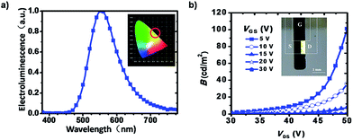 | ||
| Fig. 3 (a) Electroluminescent (EL) spectra of the devices, inset: the CIE coordinates; (b) the control of emission via VDS and VGS, inset: the photo of a working device. | ||
Interestingly, the emission of the devices is in the region near the drain electrode and the brightness turns stronger with the increase of VDS and decrease of VGS (Fig. 3b), which is contrary to our previous study based on pure iridium complex,15 in which, the emission of the devices is near the source electrode and the brightness turns stronger with the decrease of VDS and increase of VGS.
Considering the wide band gap of PMMA and barrier of ion migration caused by it, the working mechanism of the devices with PMMA may be different from that of the device based on pure iridium complex.
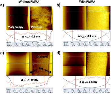
To prove our suggestion, the KPFM was utilized. Films of [Ir(ppy)2pyim]PF6 with and without PMMA were respectively fabricated on ITO substrates, and two Ag electrodes with the channel length of 50 nm were deposited on each film. As shown in Fig. 4a–d, the interface between Ag electrodes and iridium complex (with 33% or without PMMA) channel could be clearly distinguished.
During the KPFM tests, the morphology images of the samples were derived at the same time with the surface potential images. It is obvious that the surface potential of pure iridium complex is lower than that of Ag electrode (Fig. 4a), suggesting holes are easier to be injected from Ag to the pure film. After mixed with PMMA, the surface potential becomes higher than that of Ag electrode (Fig. 4b), indicating holes are more difficult to be injected from Ag to the mixed film. Therefore, for the device with pure iridium complex, the emission of the device turns stronger with the increase of VGS. On the contrary, for the device with mixed film, the emission turns stronger with the decrease of VGS.
Furthermore, we applied voltages (15 V for pure channel and 30 V for mixed channel) on the Ag electrodes for 10 minutes. Fig. 4c and d show the change of surface potential at the two edges of the channel. For the pure iridium channel, the potential difference of these two edges became larger (from −0.5 mV to −10 mV), indicating electrochemical double layers (EDLs) were formed at the interface of Ag electrodes and the iridium film, which was in agreement with our previous study.15 However, for the iridium/PMMA channel, no obvious change was observed even a larger voltage (30 V) was applied, suggesting EDLs were not formed because PMMA prevented the migration of ions.
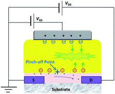
The working procedures of the device based on mixed film can be described as followings (Fig. 5): when a positive gate voltage is applied to device, negative charges will accumulate at the interface of the gate electrode and dielectric layer (the [Ir(ppy)2pyim]PF6/PMMA mixed layer), and positive charges will accumulate at the interface of dielectric layer and semiconductor layer. The induced electrons in the channel will form a drain current under applied VDS. At this time, typical transistor behaviours can be observed.
When the VDS turns larger, VDG ≥ 0, a pinch-off point is formed in the channel and drain current tends to be saturated. As the surface potential of the mixed layer is higher than that of the Ag electrode, holes are difficult to be injected from the gate electrode to the dielectric layer. However, with the help of the vertical electric field formed between gate and drain electrodes by VDG, holes are easier to be injected from ZTO near the drain electrode rather than gate electrode and then drift to the bulk of the dielectric layer. When VDG becomes much larger, electrons will be injected from gate electrode and recombine with holes to generate photons and give light emission. The emission brightness becomes higher as VDG becomes larger (VDS turns higher and VGS turns lower). Moreover, VDS will influence the pinch-off point and thus control the emission zone to be near the drain electrode.
While for device based on pure iridium complex, as the surface potential of iridium complex is lower than that of Ag gate electrode, holes are easy to be injected from gate electrode under a positive gate voltage.15 Electrons accumulated at ZTO interface near source electrode will be injected from there to recombine with holes. Therefore, the emission brightness turns higher with the increase of VGS. VDS will form a pinch-off point, influencing the emission brightness and limiting the electron injection and light emission zone to be near the source electrode. Thus, different working mechanisms of devices with and without PMMA can be explained.
Conclusions
In conclusion, we have demonstrated a multifunctional device with transistor characteristics and area light emission property based on [Ir(ppy)2pyim]PF6. Systematic research has been carried to optimize the device performance by mixing [Ir(ppy)2pyim]PF6 with different mass concentration ratios of PMMA. Furthermore, we explained the different working mechanisms of the devices with or without PMMA through KPFM. Although the operation voltages of [Ir(ppy)2pyim]PF6 device are high, our study verified the great potential of iridium complexes to be used in transistors, which may lead to the exploration of novel materials for multifunctional devices. Moreover, the working mechanism explanation based on KPFM may open up new ways for mechanism analysis of optoelectronic devices.Acknowledgements
The authors would like to thank the National Key R&D Program of “Strategic Advanced Electronic Materials” (No. 2016YFB0401100) and the National Natural Science Foundation of China (Grant No. 61474069 and 51525304).Notes and references
- D. P. Hansora, N. G. Shimpi and S. Mishra, RSC Adv., 2015, 5, 107716–107770 RSC.
- S. G. Hahm, T. J. Lee, D. M. Kim, W. Kwon, Y. G. Ko, T. Michinobu and M. Ree, J. Phys. Chem. C, 2011, 115, 21954–21962 CAS.
- Y. L. Guo, G. Yu and Y. Q. Liu, Adv. Mater., 2010, 40, 4427–4447 CrossRef PubMed.
- C. L. Ho, W. Y. Wong, Q. Wang, D. Ma, L. Wang and Z. Lin, Adv. Funct. Mater., 2008, 18, 928–937 CrossRef CAS.
- T. Michinobu, H. Kumazawa, E. Otsuki, H. Usui and K. Shigehara, J. Polym. Sci., Part A: Polym. Chem., 2009, 47, 3880–3891 CrossRef CAS.
- K. N. Narayanan Unni, R. de Bettignies, S. D. Seignon and J. M. Nunzi, Appl. Phys. Lett., 2004, 85, 1823 CrossRef.
- W. Tang, L. Feng, J. Zhao, Q. Cui, S. Chen and X. Guo, J. Mater. Chem. C, 2014, 2, 1995 RSC.
- W. Tang, J. Li, J. Zhao, W. Zhang, F. Yan and X. Guo, IEEE Electron Device Lett., 2015, 36, 950–952 CrossRef CAS.
- K. Muhieddine, M. Ullah, B. N. Pal, P. Burn and E. B. Namdas, Adv. Mater., 2014, 26, 6410–6415 CrossRef CAS PubMed.
- T. Hu, L. He, L. Duan and Y. Qiu, J. Mater. Chem., 2012, 22, 4206 RSC.
- A. Liang, G. Huang, S. Chen and H. Hou, RSC Adv., 2015, 5, 49466–49470 RSC.
- B. Tong, Q. Mei, R. Tian, M. Yang, Q. Hua, Y. Shi and S. Ye, RSC Adv., 2016, 6, 34970–34976 RSC.
- T. Yu, Y. Cao, W. Su, C. Zhang, Y. Zhao, D. Fan, M. Huang, K. Yue and S. Z. D. Cheng, RSC Adv., 2014, 4, 554–562 RSC.
- J. M. Fernández-Hernández, S. Ladouceur, Y. Shen, A. Iordache, X. Wang, L. Donato, S. Gallagher-Duval, M. de Anda Villa, J. D. Slinker, L. De Cola and E. Zysman-Colman, J. Mater. Chem. C, 2013, 1, 7440 RSC.
- J. Li, G. Dong, L. Duan, D. Ma, T. Hu, Y. Zhang, L. Wang and Y. Qiu, RSC Adv., 2014, 4, 51294–51297 RSC.
- M. Bieletzki, T. Hynninen, T. M. Soini, M. Pivetta, C. R. Henry, A. S. Foster, F. Esch, C. Barth and U. Heiz, Phys. Chem. Chem. Phys., 2010, 12, 3203–3209 RSC.
- V. Palermo, M. Palma and P. Samorì, Adv. Mater., 2006, 18, 145–164 CrossRef CAS.
- L. He, J. Qiao, L. Duan, G. Dong, D. Zhang, L. Wang and Y. Qiu, Adv. Funct. Mater., 2009, 19, 2950–2960 CrossRef CAS.
- J. Puigdollers, Org. Electron., 2004, 5, 67–71 CrossRef CAS.
- J. S. Meena, M. C. Chu, R. Singh, C. S. Wu, U. Chand, H. C. You, P. T. Liu, H. P. D. Shieh and F. H. Ko, Adv. Mater., 2014, 4, 18493 CAS.
- T. Tsuboi and N. Aljaroudi, Opt. Mater., 2008, 30, 1375–1381 CrossRef CAS.
- D. Ma, L. Duan, Y. Wei, L. He, L. Wang and Y. Qiu, Chem. Commun., 2014, 50, 530–532 RSC.
Footnotes |
| † Electronic supplementary information (ESI) available. See DOI: 10.1039/c6ra22052e |
| ‡ J. Li and W. Li contributed equally to this work. |
| This journal is © The Royal Society of Chemistry 2016 |

