Catalytic effects of electrode material on the silicon tetrachloride hydrogenation in RF-arc-discharge

R. A. Kornevab, V. M. Vorotyntseva, A. N. Petukhova, E. N. Razovc, L. A. Mochalova, M. M. Trubyanova and A. V. Vorotyntsev*a
aNizhny Novgorod State Technical University n.a. R.E. Alekseev, Nizhny Novgorod, Russia
bG.G. Devyatykh Institute of Chemistry of High-Purity Substances, Russian Academy of Sciences, Nizhny Novgorod, Russia. E-mail: an.vorotyntsev@gmail.com
cInstitute for Problems in Mechanical Engineering, Russian Academy of Sciences, Nizhny Novgorod, Russia

Received 21st August 2016 , Accepted 7th October 2016

First published on 13th October 2016


Abstract

A silicon tetrachloride reduction in RF-arc-discharge (40.86 MHz) has been experimentally studied. The electrode material significantly affects the composition of the chlorosilanes in the gas phase at the outlet of the reactor which may be attributed to high and at the same time different catalytic activity of Cu, Ni, Nb, and Zr metals belonging to the transition of d-elements and W f-elements of the periodic table. The corrosion has been observed on the electrodes with the formation of chlorides of Cu, Ni, Nb, Zr, and W metals. In the system formed by two electrodes and plasma there are three main reactive regions in which the recovery of silicon tetrachloride by hydrogen at different flows is conducted independently from each other. The analysis of exhaust gases, chemically active plasma and condensed phase by emission-spectroscopy and GCMS spectrometry made it possible to propose the mechanism of formation of observed intermediate species and final products. On the basis of the obtained results we can conclude that this type of RF-plasma discharge includes two mechanisms of plasma chemical reactions: one with the participation of active particles formed in plasma and one initiated by the catalytically-active surface of the electrode.

1. Introduction

Silicon tetrachloride is the major byproduct of polycrystalline silicon (poly-Si) production obtained through the chemical vapor deposition (CVD) process of SiHCl3.1 In the near future a drastic increase in the production capacity of poly-Si in the solar cell industry is expected. Thus, finding an efficient process of converting SiCl4 (STC) to useful products is becoming more and more important both environmentally and economically, and the reaction of hydrogenation of SiCl4 has become the focus of recent basic scientific and technological research.2

There are several approaches to hydrogenation/reduction of silicon tetrachloride. The main commercially successful process is silicon tetrachloride processing and reuse by a high-temperature hydrogenation/reduction to chlorosilanes.3 There is a number of other less widespread methods: hydrogenation with the application of highly reactive reductants (e.g. metal hydrides),4 plasma hydrogenation,5 and catalytic hydrogenation/reduction.6–14

All these methods have their own advantages and drawbacks. The disadvantages include high energy consumption; high production costs; contamination of reaction products with electroactive impurities which is unacceptable in modern microelectronic applications; necessity of toxic waste disposal; complicated apparatus and low product yield.

Recent years have seen great advances in catalytic hydrogenation/reduction processes of chlorosilanes. The following catalysts are in common use at the moment: Ni and Si powders and their mixtures,6,7 copper(I) oxide, copper(I) chloride, and iron(II) chloride.6,8,10 Bulan and Weber10 reduced silicon tetrachloride in the presence of aluminum, vanadium, and antimony chlorides, bromides, and iodides. Koether11 used copper silicide as a catalyst. Bohmhammel et al.12 used a niobium, tantalum, or tungsten heating element as a catalyst. Good results were obtained when applying mixtures of group 2A metals and their salts as catalysts.13 Qiguo Chen and Wenlong Chen8 used copper halides mixed with alkali metals as catalysts. Yan et al.14 proposed applying activated charcoal with a specific surface area above 104 m2 kg−1 as a hydrogenation catalyst support.

Transition metal silicides, formed by the reaction of the metal with SiCl4–H2 mixtures under hydrogenating reaction conditions, are known to allow a substantial lowering of the reaction temperature of the hydrogenation of SiCl4 as compared to the uncatalyzed reaction.15–18 Ingle and Peffley reported that copper hydride was an active catalyst which reacted with SiCl4, forming copper chloride and SiHCl3, and the process parameters affecting SiHCl3 yield.19 Meanwhile, Gusev et al. offered a plasma process, as well as a catalytic hydrogenation process, coming to the conclusion that pressure in the reaction zone plays a key role in determining the SiHCl3 yield of SiCl4 plasma hydrogenation.2

When dealing with transition metals in a catalytic reaction containing chlorine, it is important to note whether the metals are removed from the solid phase in the form of volatile metal chlorides or the silicide catalysts remain stable under the reaction conditions. Therefore, Acker and Bohmhammel reported the thermodynamics results of transition metal silicides and suggested that these can be formed in situ by reaction of metal with a SiCl4/H2 atmosphere.16

Vorotyntsev et al.20–22 performed quantum-chemical calculations of the hydrogen hydrogenation/reduction of silicon chlorides and theoretically determined the relevant activation parameters. It is of interest to experimentally determine these parameters and compare them to calculation results.

Silicon tetrachloride finds wide application in microelectronics and chemical industries, but a large amount of silicon tetrachloride formed in semiconductor silicon production is not used. The reason for this is the following: hydrogenation/reduction of silicon tetrachloride requires much energy. In view of semi-conductor silicon production scale-up the problem of silicon tetrachloride processing and reuse in semi-conductor silicon production is of great practical importance.

Thus, in both economic and environmental contexts all formed silicon tetrachloride should be converted to less energy consuming raw materials which could be used in semiconductor silicon production process with the aim of creating a closed production loop.

In addition, plasma offers sufficiently promising methods which provide a high yield of trichlorosilane (TCS) (60%).2,5,20,23–27 One important aspect is that the formation of dichlorosilane (DCS) is observed in the gas phase as the reaction product additionally to the formation of TCS.2 The process was conducted in the RF-discharge plasma at atmospheric pressure. The plasma was stabilized by means of two coaxially-arranged silicon electrodes.

The presence of DCS in gas-phase reaction products allowed assuming the catalytic effect of chemically active plasma leading to the reaction of TCS disproportionation. Apparently, electrode material which can catalyze the reaction of TCS disproportionation has an important role in this process.

The purpose of the present article was to study the effect of the electrode material on the selectivity of the reaction of hydrogen reduction of silicon tetrachloride and investigate the catalytic effect of metals on the mechanism of reaction in plasma-chemical reduction.

2. Experimental

2.1. Materials

In this work we used as the initial substances: silicon tetrachloride (STC) (99.998%, Firm HORST Ltd., Russia), helium (9[thin space (1/6-em)]999[thin space (1/6-em)]999%, “Monitoring”, Russia) and hydrogen (99.99998%, “Monitoring”, Russia). The process was controlled by gas chromatography–mass spectrometry GCMS – QP2010 Plus (Shimadzu, Japan).

In the plasma-chemical reactor we used Cu, Ni, Nb, Zr, W and Si electrodes with purity of material 99.999% (Sernia Inc., Russia).

2.2. Apparatus and procedures

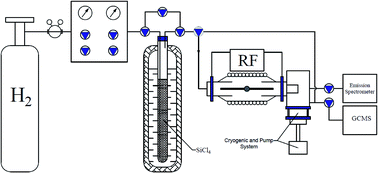
The apparatus used in our experiments is shown schematically in Fig. 1.
image file: c6ra21023f-f1.tif
Fig. 1 Setup for plasma-chemical reduction of STC.

Power of the RF generator was maintained at 350 W with frequency of 40.68 MHz. The power supplied to the discharge zone was 115 ± 5 W. After initiating a discharge by applying the RF voltage from the generator to the electrodes through a matching unit, a mixture of STC vapor and hydrogen was introduced into the discharge zone. The mixture was prepared by bubbling of hydrogen through liquid STC at a constant temperature. The flow rate of plasma-forming gas H2/SiCl4 was adjusted by mass-flow controllers within the range of (0.7–3.42) mol h−1. The mole ratio of the raw substances (H2/SiCl4) was varied in the range of (2.7–11.2). It is of key importance, for commercial applications, to be able to perform silicon tetrachloride hydrogenation at atmospheric pressure. In connection with this, we determined conditions that were optimal in terms of the trichlorosilane yield of SiCl4 hydrogenation at a pressure of 101.35 kPa (Fig. 2). The plasma reactor had the form of a quartz tube with electrodes along its axis.


image file: c6ra21023f-f2.tif
Fig. 2 Type of discharge at 101.35 kPa: (a) discharge in a hydrogen atmosphere; (b) discharge of the reaction mixture H2 + SiCl4.

The measurement of the temperature of the reactor walls was carried out with a “chromel–alumel” thermocouple along the entire length in increments of 0.05 m with the exclusion of the average zones in which the reduction with hydrogen occurred. The temperature of the reactor walls close to the formation of the plasma was 1600–1700 K, and close to the reactor outlet was 300 K.

Silicon, copper, nickel, tungsten, niobium and zirconium were chosen as electrode materials.

2.3. Products analysis

2.3.1. GCMS analysis. Quantitative analysis of compounds available from the experiment was carried out by a gas chromatography method on GC “Tsvet-800” (Tswet, Russia) equipped with a thermal conductivity detector (TCD) and a vacuum sample inlet system. For separation of components after synthesis we used a 3 m long packed column with Chromaton N-AW-HMDS (0.16 ÷ 0.20 mm) with 15% liquid phase of E-301 at 373 K for 6 minutes. The results obtained were processed with “Tswet – analytic” software. Qualitative analysis of the major reaction products was carried out on gas chromatography-mass spectrometry complex Shimadzu “GCMS – QP2010Plus” (Shimadzu, Japan) with a vacuum sample inlet system through automatic injection valve (Valco Instruments Co Inc, USA). Reaction products were separated on an Agilent capillary column with a stationary phase based on trifluoropropylmethylpolysiloxane at 323 K for 10 minutes; carrier gas – helium 7.0 (99.99999%). Reaction products were identified with the help of NIST-11 database of mass spectra and “GCMS Real Time Analysis” software.
2.3.2. SEM analysis. Microrelief the SEM images were obtained by Tescan Vega II electron microscope at the voltage of 20 kV with backscattered electron (BSE) detector and detector of reflected electrons (RE detector) with zooming from 500 to 8000 and 20[thin space (1/6-em)]000. The use of BSE and RE detectors allows obtaining more contrast images in comparison with SE detector. Moreover the BSE detector allows conducting the elementary analysis of the surface based on the dependence of molecular weight of element from the brightness of the surface. More bright part of the image corresponds to the presence of more heavy elements there.

X-ray microanalysis obtained in the “Analysis mode” of INCA Energy 250 energy-dispersive spectrometer (Oxford Instruments) to estimate the concentration of individual chemical elements on the surface of the material. Quantitative X-ray microanalysis was carried out by comparison of the measured intensity of X-ray lines generated in the sample with intensities of corresponding lines of a standard sample. The concentration of the element was calculated from the ratio of the intensities of the sample and the standard with a known concentration of the element.

2.3.3. Optical emission spectroscopy analysis. The gasphase analysis is performed by optical emission spectroscopy (OES) in the range of 350 ÷ 950 nm by emission spectrometer HR4000CJ-UV-NIR, which detects the emission of excited species in the plasma through a sapphire window set on the reactor side wall. According to the required resolution, a 1 m or a 25 cm monochromator is used.
2.3.4. Gravimetric analysis. All of the electrodes used in the experiments were weighed before and after the plasma-chemical process of STC reduction. Measurement of the mass of the electrode was carried out with an accuracy of 1 × 10⁻⁴ g by analytical balance DV114C (Ohaus Discovery, Switzerland). Yield of silicon was determined by the difference between the masses of the electrodes before and after the experiments considering the amount of STC passed through the plasma.

3. Result and discussion

3.1. Selection of optimal operating conditions

Initially, the conversion of TCS was investigated based on the data of molar ratio of the reagents for a silicon electrode (Fig. 3). The dependence of the TCS content was extreme. The maximum yield of trichlorosilane (44%) was observed in the gas phase at the ratio H2/SiCl4 = 5.9. With further increase of hydrogen concentration the yield of TCS was reduced. Maximum yield of DCS was 5%. The yield of silicon increased from 8 to 47% with increasing hydrogen concentration.
image file: c6ra21023f-f3.tif
Fig. 3 The dependence of the overall degree of STC conversion on H2/SiCl4 mole ratio. 1 – STC; 2 – TCS; 3 – silicone (from silane and MCS); 4 – DCS.

Further experiments were carried out at constant molar ratio H2/SiCl4 = 5.9. During the experiment depending on the material of the electrodes the reaction products in the gas phase were the following: TCS, DCS, MCS (monochlorosilane), MS (silane), hydrogen chloride, and unreacted STC. At the ends of the electrodes the formation of a precipitate in the form of melt drops was observed.

3.2. Effect of the electrode material on the STC hydrogenation

The composition of chlorosilanes and silane in gas phase reaction products depending on the material of the electrodes is shown in Table 1. It is seen that when using copper as electrode material, the formation of 60% silane is observed in a gas phase. Table 2 presents the data on the precipitation on electrode, it is seen that the precipitate formed on the copper electrode contains silicon, copper and chlorine in a ratio Si/Cu/Cl = 88%/9%/3%.
Table 1 Composition of chlorosilanes and silane in gas phase reaction products depending on the electrode material
The electrode material Composition of chlorosilanes and silane gas phase reaction products, %
SiCl4 SiHCl3 SiH2Cl2 SiH3Cl SiH4
Si 52 43 5
Cu 35 5 60
Ni 50 50
Nb 39 10 7 19 25
Zr 54 21 5 7 13
W 32 38 3 7 20


Table 2 The composition of the precipitate on the electrodes
The electrode material The precipitate on the electrodes, %
Si Cu Ni Nb Zr W Cl
Cu 88.0 9.0 3.0
Ni 76.2 19.8 4.0
Nb 96.5 2.0 1.5
Zr 97.2 1.6 1.2
W 98.0 1.0 1.0


When nickel is used as electrode material (Table 1) the formation of 50% TCS is observed in the gas phase reaction products. The precipitate formed on the electrodes (Table 2) contains silicon, nickel and chlorine in a ratio of Si/Ni/Cl = 76.2%/19.8%/4%.

When tungsten, niobium, and zirconium are used as electrode material in the gas-phase reaction products, the formation of TCS, DCS, MCS and silane (Table 1) is observed.

Fig. 5 shows micrographs of silicon electrode relief before and after plasma-chemical reaction reduction of the STC. It's seen that the electrode surface is subjected to a strong etching with chlorine and further growth in etching silicon structures. Other electrodes have a similar structure, however, in the case of Cu, Ni, Nb, Zr, W the chlorides of the electrode material appear additionally, which can be seen in Fig. 4, and their quantitative composition is presented in Table 2.


image file: c6ra21023f-f4.tif
Fig. 4 The electrodes after the plasma-chemical reaction of STC reduction.

image file: c6ra21023f-f5.tif
Fig. 5 SEM of Si electrode (a – before reaction, b – after reaction).

3.3. Modeling of temperature fields in the reactor

For a preliminary assessment of the gas temperature in the plasma a simulation by the equation of heat balance was performed in view of the main components of heat exchange: power withdrawn from the zone of the plasma discharge by electrodes (Wel), scattering in the form of a radiant energy (Wrad), and power spent for heating of gas (Wg):28
 
W = Wel + Wrad + Wg (1)

Power withdrawn by electrodes in the form of the radiant energy was calculated by the equation of heat conductivity and Stefan–Boltzmann equation. It was about 92 and 8 W, respectively. Determined from eqn (1) the power going into heating the gas was approximately 15 W. The value of the gas temperature Tg in the zone of the plasma discharge was determined from the relation

 
Wg = CpQ(TgTin), (2)
where Q is a flow of reactants, Cp – heat capacity of gas, Tin – temperature of gas at inlet in the reactor.

Value of Tg was 850 ± 50 K.

A similar result follows from thermodynamic analysis,29 according to which a hydrogenation process of silicon tetrachloride to trichlorosilane with the yield up to 50% occurs at Tg below 1000 K. This fact is consistent with the calculated Tg ∼850 K and experimental yield of trichlorosilane of about 45%.

The study of thermal processes occurring in the reactor was conducted using numerical simulations with the use of experimentally measured value of the power supplied to the discharge zone, temperature distribution of a reactor wall along its length, geometry of the reactor, and also individual characteristics of hydrogen, SiCl4, and quartz.28

The plasma zone is a sphere of 7 mm radius contacting with electrodes. The preset temperature of the electrodes in points of their contact with plasma is 1700 K. An energy source is created in the reactor for the simulation of plasma. A cylinder of a radius R = 13.75 mm and a height of H = 25 mm. The density of energy is given by the formula:

 
q = [1 − 8 × 10⁵(h + H)2R2, (3)
where h is the cylinder radius.

The density of energy is set so that its total quantity in the region of release could consist of 15 W. Mathematically, a task of heat exchange in hydrodynamic flow of a gas mixture H2 + SiCl4 was posed. A mode of gas movement was turbulent. The mixture reacted in the flow is considered in view of heat transfer by means of a convection and heat conductivity and described by a set of partial differential equations.28

Fig. 6 shows the contours of the plasma chemical reactor equipped with nozzles and electrodes installed coaxially and opposite to each other, and also isothermal surfaces in the volume relative to the reactor geometry (axis Y) and the temperature distribution along the length of electrodes (axis X). Due to the fact that the electrode is cooled by the gas mixture flowing through the nozzle, a temperature of an end part of the electrode is 300 K. Due to heat transfer between the electrode and the gas mixture the last enters the reaction chamber at T = 600 K and that contributes to the reduction reaction of SiCl4. A temperature value in the contact point of electrodes with the plasma consists of 1700 K.


image file: c6ra21023f-f6.tif
Fig. 6 Scheme of plasma chemical reactor, isothermal surfaces and a dependence of relative proportions of the flow of reaction mixture on the temperature.

In physical experiment the form of the plasma is the sphere of radius of about 7 mm (Fig. 3, dashed line) slightly displaced towards the top surface of the reaction chamber since the outlet of the reacted gas mixture is on top. This zone according to performed modeling is in the range of temperatures 950–1700 K. The lower limit of the temperature range coincides with value of gas temperature calculated by the heat balance equation, according to which Tg is in the range of 800–900 K.

Fig. 6 shows a dependence of the relative proportion of the flow of the reaction mixture on temperature and diameter of the plasma chemical reactor. It is evident that 10% of the reaction mixture passes through the temperature zone of 950–1700 K; 50% through the 650–1700 K zone, and 100% through 450–1700 K zone. This dependence indicates that TCS and DCS are formed not so much in the discharge zone as outside it, as the main amount of the reaction mixture passes through the zone of 650–950 K. It can be argued that the plasma is a source of active particles of specific type, which diffuse from the discharge zone and cause the reduction reaction of silicon tetrachloride to trichlorosilane in the region of afterglow. In the temperature zone (650–950 K) about 50% of SiCl4 is delivered, which is transformed in trichlorosilane with about 100% conversion. Formation of dichlorosilane by the disproportionation of TCS most likely proceeds in low temperature zone. Formation of silicon of about 10% yield, in contrast, occurs in the high temperature zone of 950–1700 K, wherein about 10% SiCl4 is fed.

3.4. Reaction mechanism

Based on the analysis of the distribution of thermal fields in the volume of the reactor, carried out by using numerical simulation28 it was found that in this case the reaction area can be divided into three temperature zones: 450–650 K, 650–950 K, and 950–1700 K.

Taking into account the results of calculation of temperature zones and yield of chlorosilanes, silane, and silicon, observed experimentally, there are three main areas, describing the SiCl4 conversion mechanism in the realized experimental conditions, where the process of plasma chemical recovery of silicon tetrachloride with hydrogen and the formation of chlorosilanes, silane, and silicon proceeds independently from each other and according to different mechanisms:

- High-temperature plasma area (950–1700 K);

- Near-electrode area (650–950 K);

- Volume area (extends beyond the boundary of plasma formation (450–650 K)).

We can assume that in plasma where the temperature of heavy particles reaches 950–1700 K, the gas heats up and the generation of active particles image file: c6ra21023f-t1.tif takes place. The hydrogenation of STC in the presence of metals takes place in two ways. The main chemical reaction responsible for the recovery process is the reaction of STC:2,29,30

H2 → 2Ḣ

image file: c6ra21023f-t2.tif

SiCl4 + 2Ḣ → SiHCl3 + HCl

image file: c6ra21023f-t3.tif

image file: c6ra21023f-u1.tif

ṠiCl3 + Ḣ → SiHCl3

SiCl4 + 2H2 → Si + 4HCl

Cl2 + H2 → 2HCl + e

ṠiCl2 + HCl → SiHCl3
where image file: c6ra21023f-t4.tif – vibrationally excited of the hydrogen molecule.

In addition, the presence of the considered particles in the emission spectra, obtained in30,31 Fig. 7, acts as a confirmation of this mechanism.


image file: c6ra21023f-f7.tif
Fig. 7 Optical emission spectra of SiCl4–H2–Ar mixture (a)30 and SiH3Cl–H2–Ar mixture of different content of hydrogen (b)31 in RF capacitive plasma discharge.

The second way was formation of a metal hydride.

Me + H2 → (H − Me − H)

2(HMe − H) + (Cl3Si − Cl) → {(Cl3Si − H) + (HMe − Cl)} → ⋯→ SiH4 + 2MeCl2

In ref. 3 in the reduction of STC by titanium hydride the reaction product contained TCS – 27%, DCS – 21%, MCS – 13%, silane – 8%. When using lithium aluminum hydride32 silane yield is 99%. When using a copper catalyst33 reaction product contained DCS – 27% and MCS – 6%.

Therefore, in near-electrode area with a copper electrode in the range of 650–950 K, the formation of silane is possible through activated complex with particles SiCl2:

1st: hydride generation

image file: c6ra21023f-u2.tif

2nd: dichlorosilylene generation

image file: c6ra21023f-u3.tif

3rd: dichlorosilylene hydrogenation to dichlorosilane

image file: c6ra21023f-u4.tif

4th: dichlorosilane hydrogenation to silane

image file: c6ra21023f-u5.tif

5th: copper chloride hydrogenation (etching electrode)

CuCl2 + H2 → Cu + 2HCl

The main product of the reaction is monosilane which is in good agreement with similar works, where the use of a catalyst of Cu/MWCNT the monogermane was obtained.34

The nickel electrode has insufficient surface energy to form SiCl2, so the reaction proceeds with the formation of TCS:35,36

image file: c6ra21023f-u6.tif

Note, however, that according to ref. 6 in plasma in these conditions the formation of atomic hydrogen is also possible. This in turn leads to an interaction of ṠiCl3 with Ḣ by the reaction:

ṠiCl3 + Ḣ → SiHCl3

The reaction may also be carried out for W, Nb and Zr electrodes. However, in this case, interaction of ṠiCl2 with Ḣ leads to the formation of DCS of the reactions:

ṠiCl2 + 2Ḣ → SiH2Cl2

ṠiCl2 + H2 → SiH2Cl2

In the volume area of the electrode the formed DCS disproportions producing TCS, MCS, and silane according to the reactions:

2SiH2Cl2 → SiHCl3 + SiH3Cl

2SiH3Cl → SiH4 + SiH2Cl2

This suggestion is consistent with the experimental data in Table 2, according to which DCS concentration in the reaction products is small in comparison with the concentrations of TCS, MCS and silane.

Thus, from the above analysis it becomes clear that the plasma gas is a source of heat and active particles. The formation of TCS in the field of high-temperature plasma (950–1700 K) is possible with the participation of atomic hydrogen, vibrationally excited hydrogen molecule, as well as through the intermediate particles ṠiCl2, ṠiCl3. The silicon is deposited on the ends of the electrodes at a temperature of 1400–1700 K by thermal reduction. In the near-electrode area formation of chlorosilanes and silane is carried out with the participation of the activated complex. In the case of formation of DCS during the interaction between STC and the electrodes its disproportionation to TCS and silane is possible.

4. Conclusion

On the basis of obtained results we can conclude that in this type of RF-plasma discharge both the mechanisms of plasma chemical reactions with participation of active particles formed in plasma image file: c6ra21023f-t5.tif, and the mechanisms of chemical reactions initiated by the catalytically-active surface of the electrode via intermediate particles H, SiCl2, MCl2 (where M is Cu, Ni, Nb, Zr, W) are realized.

In the system formed by the two electrodes and a plasma there are three main reactive regions in which the recovery of silicon tetrachloride by hydrogen at different flows takes place independently from each other.

The electrode material significantly affects the composition of the chlorosilanes in the gas phase at the outlet of the reactor which may be attributed to high and at the same time different catalytic activity of Cu, Ni, Nb, Zr, belonging to the transition d-elements and W f-element of the periodic table. It can be observed as corrosion of the electrodes with the formation of chlorides of Cu, Ni, Nb, Zr, and W metals. From the point of view of synthesis of chlorosilanes and corrosion-resistance for the recovery process, the silicon tetrachloride hydrogen by RF-arc-plasma discharge with a tungsten electrode is the most effective.

Acknowledgements

This work was financially supported by the Ministry of Education and Science of the Russian Federation (in part of the GCMS and SEM characterization), project part of State tasks, No. 10.695.2014/K, by the Russian Foundation of Basic Research, Project No. 16-38-60192 mol_a_dk in part of disproportionation of TCS and Project No. 15-48-02184 in part of optical emission spectroscopy.

References

  1. J. Leea, W. Leea, Y. Parka, H. Kima, N. Kanga and K. Yoonb, et al., Catalytic conversion of silicon tetrachloride to trichlorosilane for a poly-Si process, Sol. Energy Mater. Sol. Cells, 2012, 105, 142–147 CrossRef.
  2. A. Gusev, R. Kornev and A. Sukhanov, Preparation of Trichlorosilane by Plasma Hydrogenationof Silicon Tetrachloride, Inorg. Mater., 2006, 42, 1023–1026 CrossRef CAS.
  3. W. Weigert, E. Meyer-Simon and R. Schwarz, inventor, Process for the production of chlorosilanes, US Pat., 4217334, Deutsche gold- und silber-scheideanstalt vormals roessler, assignee, 27 Dec 1978.
  4. P. Taylor, Purification Techniques and Analytical Methods for Gaseous and Metallic Impurities in High Purity Silane, J. Cryst. Growth, 1988, 89, 28–38 CrossRef CAS.
  5. K. R. Sarma and M. J. Rice, inventor, High pressure plasma hydrogenation of silicon tetrachloride, US Pat., 4309259, Motorola, Inc., assignee, 09 May 1980.
  6. Z. Shen, K. Wu; D. Yan, J. Liu and C. Tang, inventor, Apparatus for producing trichlorohydrosilicon by hydrogenation of silicon tetrachloride, China patent 2547719, China Nonferrous Engineering Design & Research Institute, assignee, Apr 2003.
  7. Y. Zhang, Z. Li and L. Ma, inventor, Method for producing trichlorosilane by coldly hydrogenating silicon tetrachloride, China patent 101618874, Luoyang century a new source of silicon Technology Co, assignee, 27 Apr 2011.
  8. Q. Chen and W. Chen, inventor, Method for preparing trichlorosilane, China patent 101759189, Jiangsu to Silicon Technology Development Co. Ltd, assignee, 7 Mar 2009.
  9. Y. Zhou, Z. Jiang, R. Zhang and M. Fan, inventor, Preparation method and application of catalyst used in hydrogenation of silicon tetrachloride, China Patent 101816946, BYD Co. Ltd, assignee, 1 Sep 2010.
  10. A. Bulan and R. Weber, inventor, Bulan A., Weber R., assignee, Method for producing trichlorosilane, US Pat., 20040028593, 12 Feb 2004.
  11. S. Koether, Reaktionen im System Metall–Silicium–Chlor–Wasserstoff unter dem Gesichtpunkt der heter ogenen Katalyse, Dissertation zur Erlangung des akadery mischen Grades, Freiberg, 2007.
  12. K. Bohmhammel, S. Kother, G. Roewer, I. Rover, J. Monkiewicz and H.-J. Hone, inventor, Degussa A. G., assignee, Method for the production of HSiCl3 by catalytic hydrodehalogenation of SiCl4, US Pat., 20070173671, 26 Jul 2007.
  13. W. Ding, Z. Wang, J. Yan and W. Xiao, CuCl-Catalyzed Hydrogenation of Silicon Tetrachloride in the Presence of Silicon: Mechanism and Kinetic Modeling, Ind. Eng. Chem. Res., 2014, 53, 16725–16735 CrossRef CAS.
  14. W. Ding, Y. Yan and W. Xiao, Hydrogenation of Silicon Tetrachloride in the Presence of Silicon: Thermodynamic and Experimental Investigation, Ind. Eng. Chem. Res., 2014, 53(27), 10943–10953 CrossRef CAS.
  15. J. Acker and K. Bohmhammel, Reactivity of intermetallic compounds: a solid state approach to direct reactions of silicon, J. Phys. Chem. B, 2002, 106, 5105–5117 CrossRef CAS.
  16. J. Acker, I. Röver, R. Otto, G. Roewer and K. Bohmhammel, Formation of transition metal silicides by solid-gas reactions: thermodynamic and kinetic consideration, Solid State Ionics, 2001, 142, 583–591 CrossRef.
  17. K. Bohmhammel, G. Roewer and H. Walter, Hydrodehalogenation of chlorosilanes in the presence of metal silicides: experimental studies of gas and solid phase composition related to thermodynamic calculations, J. Chem. Soc., 1995, 91, 3879–3882 CAS.
  18. W. Mo rke, F. Vogt and K. Wendlandt, Catalytical conversion of silicon tetrachloride to trichlorosilane, J. Chem. Soc., Faraday Trans., 1993, 89, 1085–1087 RSC.
  19. W. Ingle and M. Peffley, Kinetics of the hydrogenation of silicon tetrachloride, J. Electrochem. Soc., 1985, 132, 1236–1240 CrossRef CAS.
  20. A. Vorotyntsev, A. Petukhov, I. Vorotyntsev, T. Sazanova, M. Trubyanov and I. Kopersak, et al., Low-temperature catalytic hydrogenation of silicon and germanium tetrachlorides on the modified nickel chloride, Appl. Catal., B, 2016, 198, 334–346 CrossRef CAS.
  21. A. Vorotyntsev, S. Zelentsov, V. Vorotyntsev, A. Petukhov and A. Kadomtseva, Quantum-chemical simulation of the dissociative chemisorption of hydrogen on metal surfaces of nanoclusters, Russ. Chem. Bull., 2015, 64(4), 759–765 CrossRef CAS.
  22. A. Vorotyntsev, S. Zelentsov and V. Vorotyntsev, Quantum chemical simulation of silicon tetrachloride hydrogenation, Russ. Chem. Bull., 2011, 60(8), 1531–1536 CrossRef CAS.
  23. K. R. Sarma and C. S. Chanley, inventor, Process for the hydrogenation of silicon tetrachloride, US Pat., 4542004, Solavolt Int, assignee, 17 Sep 1985.
  24. Z. Lu and W. Zhang, Hydrogenation of silicon tetrachloride in microwave plasma, Chin. J. Chem. Eng., 2014, 22(2), 227–233 CrossRef CAS.
  25. V. V. Gushchin, F. V. Petrusevich, Y. A. Revenko, S. A. Muravitsky, P. M. Gavrilov, M. V. Bolgov, A. I. Levinsky and G. N. Gromov, inventor, The method for producing trichlorosilane by plasma hydrogenation of silicon tetrachloride and device for its implementation, Russian Federation patent 350558, Mining and Chemical Combine, assignee, 09 Apr 2007.
  26. L. Wu, Z. Ma, A. He and J. Wang, Studies on destruction of silicon tetrachloride using microwave plasma jet, J. Hazard. Mater., 2010, 173(1), 305–309 CrossRef CAS PubMed.
  27. A. Deryzemlia, P. Kryshtal, D. Malykhin, V. Radchenko and B. Shirokov, Deposition of nanocrystaline silicon films into low frequency induction RF discharge, Probl. Neurosurg., 2014, 1(89), 147–150 Search PubMed.
  28. R. Kornev, V. Shaposhnikov and A. Kuz'min, Gas-Dynamic and Thermal Processes in the Synthesis of Trichlorosilane by Hydrogen Reduction of Tetrachloride in a High-Frequensy Discharge, Russ. J. Appl. Chem., 2014, 87(9), 1246–1250 CrossRef CAS.
  29. E. Sirtl, L. Hunt and D. Sawyer, High temperature reactions in the silicon-hydrogen-chlorine system, J. Electrochem. Soc., 1974, 121(7), 919–925 CrossRef CAS.
  30. G. Bruno, P. Capezzuto, G. Cicala and F. Cramarossa, Mechanism of silicon film deposition in the RF plasma reduction of silicon tetrachloride, Plasma Chem. Plasma Process., 1986, 6(2), 109–125 CrossRef CAS.
  31. L. Mochalov, R. Kornev, A. Nezhdanov, A. Mashin and A. Lobanov, et al., Preparation of Silicon Thin Films of Different Phase Composition from Monochlorosilane as a Precursor by RF Capacitive Plasma Discharge, Plasma Chem. Plasma Process., 2016, 36(3), 849–856 CrossRef CAS.
  32. D. Katsoulis, R. T. Larsen, M. J. McLaughlin and W. Sparschu, inventor, Method for preparing a trihalosilane, US Pat., 8765090, Dow Corning Co, assignee, 1 Jul 2014.
  33. C. E. Erickson and G. H. Wagner, inventor, Hydrogenation of halogenosilanes, US Pat., 2595620, Union Carbide & Carbon Co, assignee, 6 May 1952.
  34. A. Kadomtseva, A. Vorotyntsev, V. Vorotyntsev, A. Petukhov, A. Ob’’edkov, K. Kremlev and B. Kaverin, Effect of the catalytic system based on multi- walled carbon nanotubes modified with copper nanoparticles on the kinetics of catalytic reduction of germanium tetrachloride by hydrogen, Russ. J. Appl. Chem., 2015, 88(4), 595–602 CrossRef CAS.
  35. A. Vorotyntsev, G. Mochalov and V. Vorotyntsev, Kinetics of catalytic hydrogen reduction of SiCl4 in the presence of nickel chloride, Inorg. Mater., 2013, 49(1), 1–5 CrossRef CAS.
  36. A. Vorotyntsev, V. Vorotyntsev, A. Petukhov, A. Kadomtseva, I. Kopersak and M. Trubyanov, et al., Kinetics of Germanium Tetrachloride Reduction with Hydrogen in the Presence of Pyrolytic Tungsten, Inorg. Mater., 2016, 52(9), 919–924 CrossRef CAS.

This journal is © The Royal Society of Chemistry 2016
Click here to see how this site uses Cookies. View our privacy policy here.