An antireflection method for a fluorinated ethylene propylene (FEP) film as short pulse laser debris shields

S. F. Chen*, B. L. Chen, C. Q. Huang, X. D. Jiang, Y. Fang and X. Luo*
Research Center of Laser Fusion, China Academy of Engineering Physics, Mianyang, Sichuan 621900, China. E-mail: luox76@gmail.com

Received 17th August 2016 , Accepted 4th September 2016

First published on 5th September 2016


Abstract

Debris mitigation is a major challenge for all high peak power laser system. Thus, fabrication of special polymer films to protect from target debris is significant. Fluoride polymers, representative of fluorinated ethylene propylene (FEP), have excellent ultraviolet-visible transmission, laser-induced damage thresholds and mechanical properties, and stand a good chance to be used as debris shields. However, the transmittance of FEP is still lower than that of fused silica glass and needs to be improved before it is really used in the laser field. The difficulty is that modifying on inactive fluoride polymers is very difficult. In this study, we developed a simple method to create large-scale porous silica antireflection layers on inactive FEP film. The method combines oxygen plasma processing and the sol–gel process, and the maximum transmittance of the coated FEP film reaches 99.28% as compared to 96.83% for the uncoated FEP film. Aiming at the wavelength of 351 nm, the transmittance of the coated FEP film reaches 97.48% compared to 93.42% for the uncoated FEP film. This antireflection FEP film has considerable applications in the high peak power laser field.

Introduction

Debris mitigation is a major challenge for all high peak power laser systems; the impulsive debris will pollute and damage the optical element and diagnostic facility. Thus, fabrication of special polymer films to protect from target debris is significant.1–4 In the Z-Backlighter laser facility, Sandia National Laboratories developed a type of nitrocellulose, which can be used as the target debris shields.5 However, nitrocellulose cannot be used in the NIF laser facility for the working wavelength of 351 nm as nitrocellulose has obvious absorption at this wavelength. Actually, almost all polymers have absorption at 351 nm, thus it is very difficult to develop available polymers that can be used as debris shields in the NIF laser facility. Fluoride polymers are well known for their low absorption at ultraviolet spectral range, so in our previous research,6 fluoride polymers were investigated with respect to their optical and spectral transmission quality, absorption and damage threshold;7,8 the results indicate that fluorinated ethylene propylene (FEP) has excellent combined properties and is most probable to be used as the debris shields in the NIF laser facility. However, there is still a key problem that needs to be resolved before the FEP film can actually be used in the laser field. The problem is that the transmittance of FEP film is not enough and needs to be improved. Although the transmittance of FEP film at 351 nm is higher than 93% and higher than most other polymers, there is still a gap to the real optical element. We still found that the absorption of FEP at 351 nm is very low; the loss of light transmission is mainly coming from the high reflectance of FEP film.

For the abovementioned reasons, in order to avoid the reflection losses caused by the reflectance between the refractive indices of air and of the FEP film, we attempted to create large-scale porous silica antireflection layers on FEP film through the sol–gel process. Due to the low refractive index, the porous silica layers can reduce the light reflection coefficient. The main challenge in coating large-scale porous silica layers on the FEP film is that fluoride polymers, including FEP are inactive; they are hydrophobic and oleophobic at the same time, thus it is very difficult to coat on fluoride polymers.9 Actually, modification of fluoride polymers is always a hot and difficult research topic.10–12

In this study, we propose a method to reduce reflectance and increase transmittance of the FEP film based on the sol–gel technique. Through an oxygen gas plasma process, the interface interaction between silica sol and the FEP film can be improved. Through regulating the structure of silica gels and coating technique, transmittance of specific and single wavelengths can be improved to higher than 97%. This cladding antireflection film has considerable applications in the high peak power laser field.

Result and discussion

Fig. 1 shows the transmittance curves of original FEP films with different thicknesses. It can be observed from Fig. 1 that there is 0.24% transmittance difference between 12.5 μm and 25 μm FEP films. This means the transmittance loss of 0.24% is due to the internal absorption of FEP film with a thickness of 12.5 μm. The result indicates that the transmittance of 12.5 μm FEP at 351 nm can be improved to 99.76% in theory. However, in fact, there is always inevitable transmittance loss originating from the surface scattering or defective index matching between FEP and silica sols, and the transmittance of 99.76% is very difficult to achieve. However, the low absorption of FEP film at 351 nm provides a possibility to develop a new polymer material, which has excellent transmittance at 351 nm and can be used as short pulse laser debris shields.
image file: c6ra20760j-f1.tif
Fig. 1 Transmittance vs. wavelength curves of original FEP films of two thicknesses.

Fig. 2 shows the transmittance changes of FEP films during the plasma processing procedure. Actually, according to numerous reports,13,14 plasma processing time has a dramatic influence on the transmittance of polymer film; there are some reports about using the plasma etching technique to change the transmittance of polymer films. However, according to the result in Fig. 2, it can be observed that the transmittance of FEP film at 351 nm changes barely during the plasma processing process and even the longest duration time is up to 25 minutes. The result is very positive. If plasma processing decreases the transmittance of FEP at 351 nm, the transmittance loss must be compensated at the sol–gel procedure, the difficulty undoubtedly increasing. Fortunately, for FEP film, the problem does not exist.


image file: c6ra20760j-f2.tif
Fig. 2 Transmittance changes of FEP films at 351 nm during the plasma processing procedure.

Fig. 3 shows rhodamine B–ethanol droplets (10 mL) on the original FEP and the plasma processing FEP (bare FEP). The main component of PDMS/silica sols is ethanol; the antireflection effect of FEP is determined by the wetness between FEP film and PDMS/silica sols; in other words it is determined by the wetness between the FEP film and ethanol. It can be observed from Fig. 3 that after plasma processing for 25 minutes, the wetness between FEP and rhodamine B–ethanol solution is notably improved; the contact angles (CA, θ) of FEP and rhodamine B–ethanol solution change from 47° (bare FEP) to 5° (plasma processing FEP).


image file: c6ra20760j-f3.tif
Fig. 3 Rhodamine B–ethanol contact angles of (a) original FEP film and (b) oxygen plasma processing FEP and (c) image of rhodamine B–ethanol droplets on the original and plasma processing FEP films.

Fig. 4(a) shows the transmission spectra of the coated FEP films obtained from different dip-coating procedures. The coated FEP film shows broadband antireflection in the wavelength region from 340 nm to 800 nm. Even the transmittance of the coated FEP films is affected dramatically by the withdrawal speed during the dip-coating process; the transmittance of coated FEP film in the region 340–800 nm is improved obviously. When the withdrawal speed decreases from 30 mm min−1 to 20 mm min−1 and then to 10 mm min−1, the transmittance of FEP films at 351 nm changes from 94.74% to 97.01–97.48% in contrast to that (93.42%) of bare FEP film, except that, the maximum transmittance of the coated FEP substrate changes from 98.83% (612 nm) to 99.28% (507 nm) and then to 98.14% (456 nm) in contrast to that (96.83%, 770 nm) of bare FEP film (Fig. 4(a)). The increased transmittance is in line with the strongly reduced reflectance for the corresponding wavelengths (Fig. 4(b)). Remarkably, the entire spectrum shows reduced reflectance as compared to bare FEP film, and the minimum reflectance at 351 nm is lowered to 1.77% (10 mm min−1). Moreover, the minimum reflectance of coated FEP film is lowered to essentially 0.21% at 507 nm (20 mm min−1). The results indicate that the antireflective effect was influenced severely by the withdrawal speed. Actually, according to the previous report,17 through regulating the withdrawal speed of the dip-coating process, the antireflective effect can even be optimized for a desired wavelength and high transmittance at the desired wavelength can be achieved. In other words, the transmittance of 97.48% at 351 nm is not the best result and can be further improved through optimizing the silica sol structure and regulating the withdrawal speed of the dip-coating process.


image file: c6ra20760j-f4.tif
Fig. 4 (a) Transmission and (b) reflection spectra of the coated FEP films obtained from different dip-coating procedures.

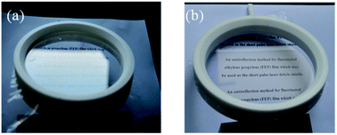
Fig. 5 shows the digital images of bare FEP film and the coated FEP film. The difference between the two images is conspicuous. Because of the high reflectance of bare FEP, the letters on the paper almost cannot be detected (Fig. 5(a)). However, after coating the antireflection layer, the letters can be observed clearly (Fig. 5(b)).


image file: c6ra20760j-f5.tif
Fig. 5 Digital images of (a) bare FEP film and (b) coating FEP film.

Experimental

FEP film samples preparation

In this study, original FEP films with thickness of 12.5 μm (purchased from Saint-Gobain Performance Plastic Corporation, New Jersey, USA) were first ultrasonically cleaned in alcohol and then in hexane solution; the cleaning time is about 10 min. Then, the films were swept by high purity nitrogen gas (99.99%). The cleaned films were fixed to an embroidery frame.

Plasma processing

The fixed FEP film elements were treated with radio frequency, low pressure plasma equipment (model: Junior plasma, Europlasma, Belgium) using oxygen gas. The sample chamber was evacuated to 100 mTorr and maintained during the process. The flow rate of oxygen was 30 sccm (standard cubic centimeters per minute) and the pressure chamber adjusted to 150 mTorr. Plasma was generated at 100 W for different predefined times of 5, 10, 15, 20 and 25 min. After that, air was introduced into the chamber and the plasma treated sample was removed. The bare FEP films were obtained.

Sol–gel coating process

PDMS/silica sols were prepared by the Stöber method15 as we have reported in our previous work;16,17 therefore, there is not detailed description in this study. All the sols were carefully filtered through 0.22 μm PVDF filters before the coating application. The silica sols were deposited on the plasma processed FEP film elements by dip coating. The silica coatings were dried at 25 °C for 1 h under static atmosphere. After that, the coated FEP films were obtained.

Conclusions

In summary, we developed a simple method that can implement large area antireflection to FEP film. The method is a combination of two simple steps, including oxygen plasma processing and sol–gel processing. The maximum transmittance of coated FEP film reaches as high as 99.28% as compared to 96.83% for the bare FEP substrate. Aiming at the wavelength of 351 nm, the transmittance of coated FEP film reaches 97.48% compared to 93.42% for the bare FEP film. In theory, the transmittance of coated FEP at 351 nm can be further improved through regulating the structure of silica gels and the sol–gel coating technique. The current approach is facile and economical and can effectively resolve the key problem of FEP film (inadequate transmittance) before it can really be used in the laser field. This research not only provided a useful material that can be used in laser field but also developed a new field of application for organic fluoride polymers.

Acknowledgements

This study was financially supported by the Development Foundation of China Academy of Engineering Physics (no. 2013A0302016) and the National Foundation of China (Grant no. 11174258).

Notes and references

  1. D. C. Eder, A. E. Koniges, O. L. Landen, N. D. Masters, A. C. Fisher, O. S. Jones, T. I. Suratwala and L. J. Suter, J. Phys.: Conf. Ser., 2008, 112, 032023 CrossRef.
  2. J. E. Andrew and K. A. Wallace, Proc. SPIE: In Laser-Induced Damage in Optical Materials, 2012, vol. 8530, p. 853023 Search PubMed.
  3. J. Andrew, D. Egan, S. Miller, A. Pearce, R. Penman and D. Scott, Proc. SPIE: In Laser-Induced Damage in Optical Materials, 2014, vol. 9237, p. 923705 Search PubMed.
  4. H. Azuma, Y. Nishimura, A. Sakata and A. Takeuchi, Appl. Surf. Sci., 2002, 197–198, 224 CrossRef CAS.
  5. J. Schwarz, P. Rambo, M. Geissel, D. Headley, M. Ramsey, and B. Atherton, Proc. SPIE: in Laser-Induced Damage in Optical Materials, 2007, vol. 6720, p. 67200Q Search PubMed.
  6. S. F. Chen, C. Q. Huang, X. D. Jiang, X. Luo, Y. Fang and W. D. Wu, Int. J. Polym. Sci., 2016, 1367537 Search PubMed.
  7. E. Leivo, T. Wilenius, T. Kinos, P. Vuoristo and T. Mäntylä, Prog. Org. Coat., 2004, 49, 69 CrossRef CAS.
  8. T. Takayanagi and M. Yamabe, Prog. Org. Coat., 2000, 40, 185 CrossRef CAS.
  9. D. O'Hagan, Chem. Soc. Rev., 2008, 37, 308 RSC.
  10. D. F. Persico and R. J. Lagow, Macromolecules, 1985, 18, 1383 CrossRef CAS.
  11. Z. Ge, X. Y. Zhang, J. B. Dai, W. H. Li and Y. J. Luo, Eur. Polym. J., 2009, 45, 530 CrossRef CAS.
  12. G. Boutevin, D. Tiffes, C. Loubat, B. Boutevin and B. Ameduri, J. Fluorine Chem., 2012, 134, 77 CrossRef.
  13. D. Kontziampasis, G. Boulousis, A. Smyrnakis, K. Ellinas, A. Tserepi and E. Gogolides, Microelectron. Eng., 2014, 121, 33 CrossRef CAS.
  14. D. Kontziampasis, V. Constantoudis and E. Gogolides, Plasma Processes Polym., 2012, 9, 866 CrossRef CAS.
  15. W. Stöber and A. J. Fink, J. Colloid Interface Sci., 1968, 26, 62 CrossRef.
  16. L. H. Yan, H. B. Lv, C. C. Wang and X. D. Yuan, Opt. Laser Technol., 2011, 43, 232 CrossRef CAS.
  17. X. X. Zhang, H. P. Ye, B. Xiao, L. H. Yan, H. B. Lv and B. Jiang, J. Phys. Chem. C, 2010, 114, 19979 CAS.

This journal is © The Royal Society of Chemistry 2016
Click here to see how this site uses Cookies. View our privacy policy here.