All-cellulose composites with ultra-high mechanical properties prepared through using straw cellulose fiber
Xiao Wei,
Wei Wei,
Yu-hu Cui,
Ting-ju Lu,
Man Jiang,
Zuo-wan Zhou* and
Yong Wang*
School of Materials Science and Engineering, Southwest Jiaotong University, Key Laboratory of Advanced Technologies of Materials, Ministry of Education of China, Chengdu 610031, P. R. China. E-mail: yongwang1976@163.com; zwzhou@home.swjtu.edu.cn; Tel: +86-28-87603042
First published on 26th September 2016
Abstract
All-cellulose composites (ACCs) materials exhibit excellent mechanical properties and attract much attention of researchers. In this work, raw straw cellulose fiber (R-SCF), alkali-treated SCF (N-SCF) and activated SCF (A-SCF) were used to prepare the ACCs, respectively. The results demonstrated that although the three SCFs exhibited similar crystalline structures, i.e. cellulose I, they exhibited different surface morphologies. Morphological characterization about the cryogenically fractured surfaces and the tensile-fractured surfaces of the ACCs, which were prepared through mixing SCF into the microcrystalline cellulose (MCC) solution and then precipitated, clearly demonstrated that the ACCs were a material with a multiphase structure. The mechanical properties of the ACCs were greatly dependent upon the interfacial adhesion between the SCF and the regenerated MCC (RMCC). Ultra-high tensile strength (650.2 MPa) was achieved for the ACCs containing the A-SCF, which was the highest tensile strength reported in the literatures for the isotropic ACCs. The reinforcement mechanism was then analyzed. This work provides new insight on preparing the ACCs with ultrahigh mechanical properties.
1. Introduction
Polymer-based composites exhibit wide application in various fields due to their light weight, chemical resistance, structure tunability and excellent comprehensive properties, etc. Compared with the application as a functional material, it is undoubted that the application as a structural material, which usually exhibits excellent mechanical properties and provides the structural supporting effect, is more fascinating because it has much wider application fields. The common strategies developed for enhancing the mechanical properties of polymer-based composites are mainly related to the introduction of fiber-like fillers, such as glass fiber, carbon nanotubes, carbon fiber, whisker, etc. However, due to the intrinsic incompatibility between polymer matrix and filler, the enhancement of mechanical properties of polymer-based composites is still limited and it is still very difficult to achieve the composites with ultra-high mechanical properties.As a material that can be obtained from natural resources, cellulose and its derivatives have great potential applications in many fields. For example, cellulose fiber can be used as a reinforcement agent to enhance the mechanical properties of other polymers.1–4 Similar to other fillers, the mechanical properties of cellulose reinforced composites are greatly dependent upon the dispersion of cellulose and the interfacial interaction between components. However, due to the relatively stronger hydrophilicity, the dispersion of cellulose in other polymers, especially in apolar polymers, and the interfacial affinity between components are relatively poor, which weaken the reinforcement effect of cellulose fiber.5–7 So far, although many strategies have already been developed to modify cellulose fiber8–12 and the mechanical properties of the composites are greatly enhanced, the composites still exhibit the multiphase structure with poor interfacial adhesion and the interfacial debonding is still unavoidable under the load condition.
Recently, all-cellulose composites (ACCs), in which both the reinforcement and matrix are cellulose, have attracted interest of researchers. Some people think that the ACCs are monocomponent since matrix is cellulose that has been dissolved and then precipitated, while the reinforcement is undissolved or partly-dissolved cellulose.13–22 In other words, because the reinforcement and the matrix have very similar chemical structures and consequently, the chemical incompatibility between fiber and matrix that is widely present in other polymer composites is then eliminated in the ACCs.20,21,23,24 Therefore, the ACCs are also thought to be the composites without or with less interface between the reinforcement and the matrix.14,20,22 Consequently, exceptional mechanical properties that are much higher than those of the traditional cellulose reinforced composites have been widely reported for the ACCs.14,17,19,20,22,25 According to the preparation procedures of the ACCs, it can be deduced that the factors that influence the mechanical properties of the ACCs are mainly related to the following aspects. The first one is the anisotropic or isotropic feature of the ACCs that is strongly depend on the dissolution and regeneration conditions.19,22,26 The second one is the different combinations of fiber, matrix, and solvent systems,14,27–29 The third one is the treatment of cellulose fiber, which is related to the removal of impurities from the surface of cellulose fiber.26,30,31 etc. Furthermore, the post-treatment of the cellulose fiber and the wet drawing of the composites is also demonstrated an efficient strategy to further enhance the mechanical properties of ACCs.32,33 For example, it is reported that the tensile strength of the unidirectional ACCs film can be enhanced up to 910 MPa,33 which is much higher than the 411 MPa of the isotropic ACCs film.34
Although many researches have been carried out to prepare the ACCs with excellent mechanical properties, the microstructure–performance relationship of the material is still not very clear. Many researchers suggest that the reinforcement mechanism is attributed to the less interface in the material, the stiffness of the cellulose fiber, and the strong interfacial interaction between fiber and matrix through hydrogen bonds, etc., all of which provide enough stress transferring from the relatively weak cellulose matrix to the relatively strong cellulose fiber.14,20,22,35 It is well known that the cellulose I exhibits much higher modulus and strength compared with the cellulose II or amorphous cellulose36,37 and therefore, in the ACCs sample, it is hardly to say that the ACCs are really monocomponent due to the difference in modulus. This indicates that there is still the interface between cellulose fiber and cellulose matrix. Obviously, the reinforcement mechanism of the fiber with cellulose I in the cellulose matrix with cellulose II and/or amorphous structure is still controversial and needs to be further investigated.
In this work, our attention was mainly focused on understanding the role of interface between fiber and matrix in determining the mechanical properties of the ACCs. The ACCs were prepared using microcrystalline cellulose (MCC) as the matrix while the straw cellulose fiber (SCF) as the reinforcement agent. To achieve this goal, different methods were selected to modify cellulose fiber to obtain the alkali-treated fiber and surface-activated fiber, and then the isotropic ACCs film with different kinds of cellulose fibers were prepared. The microstructures of cellulose fiber and the ACCs, the mechanical properties and the fractured surface morphologies were systematically investigated. Surprisingly, the ultra-high tensile strength, i.e. 650.2 MPa, was achieved for the ACCs with surface-activated cellulose fiber. To the best of our knowledge, this was the highest tensile strength for the isotropic ACCs compared with the reports in the literatures. This is very significant because this work demonstrates that through the simple activation process, which is much different from the application of cellulose nanocrystals or cellulose whiskers that they add cost and complexity to their formulation, the common SCF can be used to prepare the isotropic ACCs with ultra-high mechanical properties and expected low cost.
2. Experimental part
2.1 Materials
The SCF with a degree of polymerization of 446 was provided by Baikaiwei Chemical Reagent Co. (Si Chuan, P. R. China). The MCC (with a trade name of C104843) was provided by Aladdin Chemical Reagent Co. (Shanghai, P. R. China).2.2 Modification of SCF
Two different methods were used to prepare the activated SCF (A-SCF) and alkali-treated SCF (N-SCF), respectively. For the activated SCF, the raw SCF (R-SCF) was first immersed in distilled water at room temperature (25 °C) for 5 h, then immersed in ethanol at 25 °C for 3 h, and finally immersed in N,N-dimethylacetamide (DMAc) at 25 °C for 3 h to successively pre-swell the SCF using solvents with gradually reduced polarity. After being filtered, the A-SCF was then obtained. The alkali-treated SCF was prepared through the well-known method reported in literature,26 namely, the raw SCF was immersed into the solution of NaOH (4 wt%) at 60 °C for 4 h. After being continuously filtered and washed for several times until the pH value of the solution is 7, then the modified SCF was further vacuum-dried 80 °C for 24 h and finally, the N-SCF was obtained. For making a comparison, the raw SCF was also used to prepare the ACCs. The A-SCF and N-SCF exhibited degrees of polymerization of 401 and 356, respectively. During the modification process, the yields of N-SCF and A-SCF were about 95%. The contents of α-cellulose in the R-SCF, N-SCF and A-SCF samples are 93.3%, 95.1% and 93.8%, respectively.2.3 Preparation of the ACCs
To prepare the ACCs, the activated MCC (4 wt%) was firstly prepared through the completely same procedures used for the A-SCF. Then, the activated MCC was immersed into the solution of lithium chloride (LiCl)/DMAc containing 5 wt% LiCl. The mixture was placed at environmental temperature of 0 °C for 24 h to make sure the complete dissolution of MCC. Then, the modified SCF was mixed with the solution of MCC, after being continuously stirred at room temperature for 30 min and deformation treatment, the mixture was transferred into a watch glass and left at ambient atmosphere for 12 h. After that, a gel with a thickness of about 1 mm was formed. The gel was washed with distilled water until the solvent was completely removed. Subsequently, the gel was lightly pressed beneath filter paper to remove the residual water and then dried in a vacuum oven set at a pressure of 2.5 kPa and a temperature of 60 °C. Finally, the ACCs film with a thickness of about 0.04–0.08 mm was obtained. In this work, three different ACCs samples were prepared, i.e. ACCs/R-SCF, ACCs/N-SCF and ACCs/A-SCF, which contained R-SCF, N-SCF and A-SCF, respectively. For a comparison, the regenerated MCC sample (RMCC) was also prepared through the completely same procedures. For all the ACCs samples, the weight ratio between MCC and SCF was maintained at 50![[thin space (1/6-em)]](https://www.rsc.org/images/entities/char_2009.gif) :
:![[thin space (1/6-em)]](https://www.rsc.org/images/entities/char_2009.gif) 50.
50.
2.4 Characterization and measurements
The morphologies of the raw materials and the modified SCF, the dispersion of SCF in the ACCs, and the tensile-fractured surface morphologies of the ACCs were characterized using a scanning electron microscope (SEM) Fei Inspect (FEI, the Netherlands) with an accelerating voltage of 20 kV. To characterize the dispersion of SCF in the ACCs, the ACCs sample was cryogenically fractured in liquid nitrogen. All the samples were coated with a thin layer of gold before characterization.The crystalline structures of the modified SCF and the ACCs were investigated using a wide angle X-ray diffraction (WAXD, Panalytical X'pert PRO diffractometer with Ni-filtered Cu Kα radiation, the Netherlands). The continuous scanning angle range was set from 5° to 50° and the measurement was carried out at 50 kV and 40 mA. The crystallinity index (CrI) was calculated based on the methodology developed by Segal et al.:38
 | (1) |
 | (2) |
A UV-vis spectroscope was used to investigate the absorbance of the ACCs. All samples were 0.04 mm in thickness. The measurement was conducted on a UV-vis Spectroscopy UV-1800PC (SPECTROPHOTOMETER, Japan) in the wavelength range of 350–650 nm.
The dispersion of SCF in the ACCs was characterized using a transmission optical microscope (TOM) (ZEISS, Germany). The sample film had a thickness of about 0.04 mm.
Tensile properties measurement was conducted on a universal tensile machine AGS-J (SHIMADZU, Japan) according to ASTM: D638 at room temperature (25 °C) and a relative humidity of 55%. The width of the sample was 5 mm. The measurement was carried out at a gauge length of about 35 mm and a cross-head speed of 2 mm min−1. The average values reported were derived from the data of more than five specimens.
3. Results and discussion
3.1 Modification of SCF
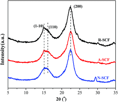
Some researchers have demonstrated that alkali treatment or partial dissolution can induce the microstructure change of cellulose fiber from cellulose I to cellulose II.39 Here, the crystalline structures of the modified SCFs were investigated using WAXD. As shown in Fig. 1, all the SCFs exhibit the similar WAXD profiles, namely, they exhibit a broad characteristic diffraction peak at 2θ range of 15–16° and a sharp diffraction peak at 2θ of 22.4°, attributing to the diffraction superposition of (![[1 with combining macron]](https://www.rsc.org/images/entities/char_0031_0304.gif) 10) and (110) crystal planes and diffraction of (200) crystal plane,40 respectively. This indicates that all the SCFs exhibit the crystalline structure of cellulose I, and the surface modification does not change the crystalline structure of the SCF possibly due to the relatively shorter treatment time and lower concentration of the solution compared with that reported in literatures. However, it is worth noting that the A-SCF and N-SCF exhibit CrI of 71% and 73%, which are slightly higher than that of the raw SCF (65%), which indicates that the surface modification facilities the removal of impurities of the SCF. According to the Scherrer relation, the R-SCF, N-SCF and A-SCF exhibit the crystal sizes of 5.9, 6.2 and 6.2 nm, respectively. This further indicates that the crystalline structure of the SCF is not changed by surface modification. Furthermore, it is worth noting that both N-SCF and A-SCF exhibit very similar surface chemistry to that of the R-SCF as confirmed by Fourier transform infrared spectroscope (FTIR) measurements (not shown here). In other words, the treatment methods applied in this work do not change the chemical structure of the SCF.
10) and (110) crystal planes and diffraction of (200) crystal plane,40 respectively. This indicates that all the SCFs exhibit the crystalline structure of cellulose I, and the surface modification does not change the crystalline structure of the SCF possibly due to the relatively shorter treatment time and lower concentration of the solution compared with that reported in literatures. However, it is worth noting that the A-SCF and N-SCF exhibit CrI of 71% and 73%, which are slightly higher than that of the raw SCF (65%), which indicates that the surface modification facilities the removal of impurities of the SCF. According to the Scherrer relation, the R-SCF, N-SCF and A-SCF exhibit the crystal sizes of 5.9, 6.2 and 6.2 nm, respectively. This further indicates that the crystalline structure of the SCF is not changed by surface modification. Furthermore, it is worth noting that both N-SCF and A-SCF exhibit very similar surface chemistry to that of the R-SCF as confirmed by Fourier transform infrared spectroscope (FTIR) measurements (not shown here). In other words, the treatment methods applied in this work do not change the chemical structure of the SCF.
The surface morphology features of the different SCFs obtained in this work were then characterized using SEM, and the typical images are shown in Fig. 2. It can be seen that for the R-SCF as obtained (Fig. 2a), the surface of the untreated cellulose was found to be considerably covered with amorphous cellulose and/or impurities. However, after being modified, both the N-SCF (Fig. 2b) and A-SCF (Fig. 2c) exhibit different surface morphologies from that of the R-SCF. First, the cellulosic microfibers displayed a neat and ordered surface, which indicates that the impurities were completely removed during the modification process, which is consistent with the observation of Peng et al.41 Second, the modified SCFs exhibit the paralleled grooves on the fiber surface. Obviously, compared with the R-SCF, the increase of surface roughness and the presence of grooves facilitate the increase of the specific area for the modified SCFs. This indicates that the contact area between fiber and matrix can be increased in the ACCs. As reported, the natural cellulose fibers are composited by crystalline cellulose in nanosize and para-crystalline, surrounded by amorphous cellulose.42 Grooves between the nanofibers were formed after the removal of amorphous cellulose, resulting in splitting the fibers into smaller sizes. Furthermore, one can see that the surface morphology of the A-SCF is slightly different from that of the N-SCF. Besides the slightly increased fiber diameter, which is related to the swell of the SCF during the activation process, the depth of the grooves is slightly smaller than that of the N-SCF. For the N-SCF, some microcracks induced by alkali treatment are observed, and these cracks can be thought as the defects of the cellulose fiber. This means that the mechanical properties of the N-SCF are possibly lower than that of the A-SCF due to the presence of more defects.
 | ||
| Fig. 2 SEM images showing the surface morphologies of different SCF. (a) R-SCF, (b) N-SCF, and (c) A-SCF. | ||
3.2 Morphology and microstructure of the ACCs
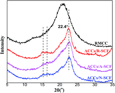
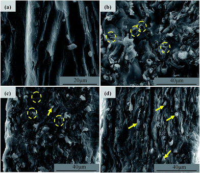
Fig. 3 exhibits the WAXD profiles of all the samples prepared in this work. It can be seen that the RMCC sample exhibits an amorphous state, which indicates that after the dissolution and regeneration process, the cellulose I structure is converted into noncrystalline condition. For all the ACCs, the characteristic diffraction peaks of cellulose I that have already been detected for the R-SCF and/or modified SCF (N-SCF and A-SCF) can be still observed. This demonstrates that the preparation process for the ACCs does not influence the crystalline structure of the SCF. Obviously, the ACCs can be thought as the material that the crystalline SCF reinforces the amorphous RMCC.Some researchers believe that the ACCs are a monocomponent material without or with less interface in the material.14,20,22 However, due to the differences in crystalline structure and mechanical properties, the stress transfer between in the ACCs is still different from that in the real monocomponent material. In this work, the SCF is crystalline structure with excellent mechanical properties while the matrix (RMCC) is the amorphous, therefore, investigating the interfacial state in the ACCs is necessary, which is favorable for better understanding the mechanical property changes of the ACCs. Fig. 4 exhibits the cryogenically fractured surface morphologies of all the ACCs samples. For a comparison, the surface morphology of the RMCC sample is also shown. Compared with the relatively homogeneous surface morphology of the RMCC sample (Fig. 4a), which exhibits the typical morphology of monocomponent, all the ACCs samples exhibit much different surface morphologies, indicating the presence of the multiphase structure. For the ACCs/R-SCF sample (Fig. 4b), besides the locally prominent structure, which is possibly related to the fracture of the R-SCF, one can also observe the sporadically dispersed holes possibly due to the pull out of the R-SCF from the matrix during the fracture process. This indicates that the interfacial adhesion between R-SCF and RMCC matrix is relatively poor. For the modified SCFs reinforced RMCC samples, the ACCs/N-SCF sample (Fig. 4c) exhibits reduced holes and increased prominent structures in the cryo-fractured surface compared with the ACCs/R-SCF sample, while the ACCs/A-SCF sample (Fig. 4d) clearly exhibits the fractured A-SCF. Obviously, compared with the ACCs/R-SCF sample, the interfacial adhesion between modified SCF and RMCC is improved, which is believed to be favorable for the enhancement of mechanical properties. Furthermore, it can be deduced that the ACCs/A-SCF sample exhibits better interfacial adhesion than that of the ACCs/N-SCF sample. The different interfacial states observed in the different ACCs samples are related to the different modification methods of the SCF. As demonstrated in Fig. 2, the surface of the R-SCF is relatively rough and some impurities and amorphous cellulose are observed on the fiber surface. This obviously prevents the close interaction between the R-SCF and the RMCC matrix. For the modified SCFs, the removal of impurities and the increase of specific surface enhance the wettability of the fiber and consequently, the ACCs exhibit better interfacial adhesion.
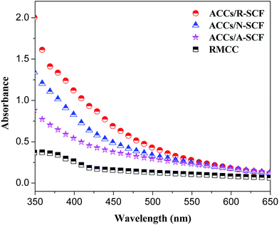
Usually, transparency is also a useful criterion used for evaluating the compatibility of the composite components. Here, the transparency of the sample films was measured and the results are shown in Fig. 5. First, all the ACCs samples exhibit higher absorbance compared with the RMCC, indicating the loss in the optical transmittance due to the presence of the large quantity of interface structure resulting in optical scattering and refraction. This further demonstrates that the ACCs are not the real monocomponent material. Second, it can be seen that among all the ACCs samples, the ACCs/A-SCF sample exhibits the lowest absorbance while the ACCs/R-SCF exhibits the highest absorbance, which indicates that the former sample exhibits the higher transparency compared with the latter sample. This further indicates that the ACCs samples containing modified SCFs exhibit better interfacial adhesion.
The TOM images of the pure RMCC and ACCs are shown in Fig. 6. Different from the relative homogeneous morphology of the pure RMCC, all the ACCs samples exhibit a large number of dark or grey zones, which represent the agglomerates of SCF. One can see that the ACCs/A-SCF sample exhibits relatively smaller agglomerates, which demonstrates that A-SCF exhibit better dispersion in the ACCs compared with the R-SCF and N-SCF. This observation is consistent with the better interfacial interaction between A-SCF and RMCC matrix.
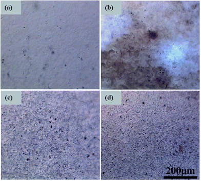 | ||
| Fig. 6 TOM images showing the dispersion of SCF in different ACCs. (a) RMCC, (b) ACCs/R-SCF, (c) ACCs/N-SCF, and (d) ACCs/A-SCF. | ||
3.3 Mechanical properties of the ACCs
To demonstrate the effect of modification on mechanical properties of the ACCs, the uniaxial tensile measurements were carried out. Fig. 7 shows the typical engineering stress–strain curves of the ACCs and the corresponding tensile properties. From Fig. 7a one can see that all the samples exhibit the similar tensile behaviors, namely, the tensile stress increases gradually with increasing tensile strain. From Fig. 7b one can see that all the ACCs samples exhibit the similar elongation at break compared with the RMCC sample, indicating that the presence of SCF does not apparently affect the tensile ductility of the samples. As expected, the ACCs/R-SCF sample exhibits much lower tensile strength and tensile modulus compared with the RMCC sample, which is believed to be the results of poor interfacial adhesion between R-SCF and RMCC matrix. Interestingly, one can see that adding the modified SCFs greatly enhances the tensile strength of the ACCs. For example, the ACCs/N-SCF sample exhibits the tensile strength of 568.6 MPa, which is 46.9% higher than that of the RMCC sample (387 MPa), and even 297.3% higher than that of the ACCs/R-SCF sample. Further enhanced tensile strength are achieved for the ACCs/A-SCF sample, and the tensile strength is enhanced up to 650.2 MPa, which is much higher than the values reported in the literature about the mechanical properties of the isotropic ACCs samples.34 Obviously, modified SCFs facilitate the improvement of the mechanical properties for the ACCs material, and activation of the SCF is possibly the most appropriate choice.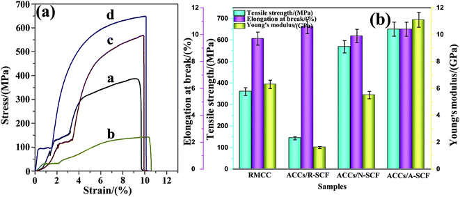 | ||
| Fig. 7 (a) Typical engineering stress–strain curves of the samples, (b) the corresponding tensile properties. (a) RMCC, (b) ACCs/R-SCF, (c) ACCs/N-SCF, and (d) ACCs/A-SCF. | ||
Studying the fractured-surface morphology is favorable for understanding the reinforcement mechanism of filler on polymer matrix. In this work, the tensile-fractured surface morphologies of all the samples were carefully investigated using SEM at different magnifications. Fig. 8 exhibits the surface morphologies of samples obtained at relatively lower magnifications. One can see that the RMCC sample exhibits a relatively smooth surface. Very coarse surface with many debonded and/or pulled out R-SCF are observed for the ACCs/R-SCF sample, which further demonstrates the poor interfacial adhesion between R-SCF and RMCC. For the samples containing modified SCFs, the surfaces are very coarse on one hand. On the other hand, it is difficult to observe the debonded and/or pulled out SCFs, which indicates that the modified SCFs and RMCC matrix are simultaneously fractured during the tensile process. Because of the high mechanical properties of modified SCFs with cellulose I structure, the samples containing modified SCFs then exhibit much higher tensile strength compared with the RMCC and/or the ACCs/R-SCF samples.
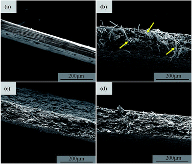 | ||
| Fig. 8 SEM images showing the tensile-fractured surface morphologies obtained at relatively lower magnifications. (a) RMCC, (b) ACCs/R-SCF, (c) ACCs/N-SCF, and (d) ACCs/A-SCF. | ||
Fig. 9 exhibits the tensile-fractured surface morphologies obtained at relatively higher magnifications. Different from the relatively smooth surface of the RMCC, very coarse surfaces are observed for all the ACCs samples, which further demonstrates the presence of the multiphase structure in the material since the different components exhibit the different mechanical responses. The drawn or debonded R-SCF is clearly observed for the ACCs/R-SCF (shown by arrows). The fractured N-SCF and A-SCF are observed for the ACCs/N-SCF and ACCs/A-SCF samples, respectively. Specifically, from Fig. 9e and f one can see that the N-SCF and A-SCF exhibit rough surfaces, which are apparently different from the surface features observed in Fig. 2b and c. First, the fiber diameters in the ACCs are greatly decreased compared with the modified SCF as prepared. Second, some lacerated fragments are observed on the fiber surfaces (shown by arrows) and the grooves that observed on the surfaces of the modified SCFs disappear completely. The decrease of fiber diameter is possibly related to the following reasons. Since the solution prepared for dissolving the MCC is also the solvent for the SCF, the decrease of fiber diameter is then possibly related to the partial dissolution of the SCF during the preparation of the ACCs. Obviously, the partial dissolution of the SCF facilitates the entanglement of the molecular chains on the fiber surface between the SCF and RMCC, which is favorable for the enhancement of interfacial adhesion. The other possibility is possibly related to the skin layer of the SCF that is peeled off during the tensile process, which also results in the decrease of the fiber diameters. Most likely, the partial dissolution intensifies the interfacial adhesion between the SCF and RMCC matrix, and the intensified interfacial adhesion facilitates the stress transferring under the load condition, which results in the peeling off of the skin layer for the SCF and consequently, resulting in the enhancement of the mechanical properties.
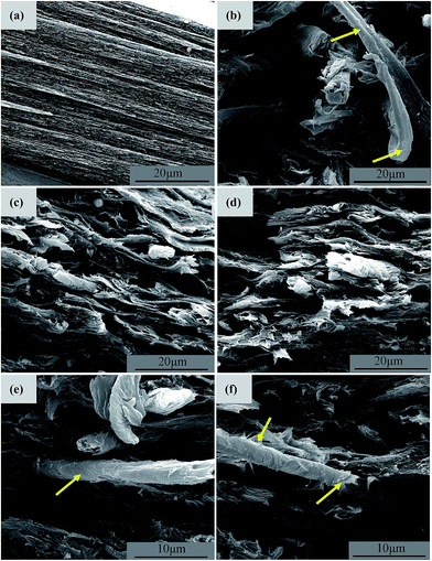 | ||
| Fig. 9 SEM images showing the tensile-fractured surface morphologies obtained at relatively higher magnifications. (a) RMCC, (b) ACCs/R-SCF, (c, e) ACCs/N-SCF, and (d, f) ACCs/A-SCF. | ||
Here, compared with the N-SCF, the A-SCF exhibits better reinforcement effect for the RMCC. To better understand the different reinforcement mechanisms of the N-SCF and A-SCF in the ACCs, more visualized schematic representations are proposed, as shown in Fig. 10. For the ACCs/N-SCF sample (Fig. 10a), the reinforcement mechanism is possibly related to the removal of impurities, the increase of aspect ratio, and the penetrating of some MCC molecular chains into the grooves of the N-SCF as shown in Fig. 2b. For the ACCs/A-SCF sample (Fig. 10b), the reinforcement mechanism can be possibly attributed to the fact that both A-SCF and MCC experience the same activation process continuously using water, ethanol and DMAc. In this condition, the A-SCF can be locally swelled to a great degree and consequently, the partial dissolution of the A-SCF is enhanced. In this condition, some molecular chains of MCC can enter into the swelled A-SCF and simultaneously, the partially dissolved A-SCF molecular chains also enter into the RMCC matrix, which increases the entanglement density of molecular chains on the fiber surface. This is believed to be favorable for the enhancement of the interfacial adhesion between A-SCF and RMCC matrix. On the other hand, the increase of aspect ratio of the A-SCF also facilitates the realization of the reinforcement effect in the ACCs. Whatever, the different mechanical responses of the ACCs prepared through different methods demonstrate the fact that the ACCs are really a material with multiphase structure and the interfacial states between SCF and RMCC matrix greatly influence the mechanical properties of the ACCs.
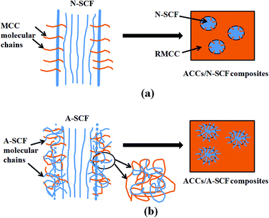 | ||
| Fig. 10 Schematic representations showing the reinforcement mechanism of the N-SCF (a) and the A-SCF (b) in the ACCs. | ||
4. Conclusions
In summary, surface modified SCF have been prepared through the different methods, including alkali treatment and activation process, respectively. Although all the SCFs exhibit the similar crystalline structure, i.e. cellulose I, the modified SCFs exhibit different surface morphologies compared with the raw SCF. Surface modification of SCF greatly influences the interfacial adhesion between SCF and RMCC matrix. Morphological characterization further demonstrates that the ACCs are really a material with multiphase structure, in which the mechanical properties are greatly dependent upon the interfacial adhesion between SCF and RMCC. Due to the largely enhanced interfacial adhesion between modified SCFs and RMCC matrix, largely enhanced mechanical properties are achieved for the ACCs. This work demonstrates that surface activation of SCF is the most appropriate method to prepare the ACCs with ultra-high mechanical properties.Acknowledgements
Authors express their sincere thanks to the National Natural Science Foundation of China (no. 51303151), the National Key Technology R&D program of China (no. 2011BAE11B01) and the Science and Technology Planning Project of Sichuan Province (No. 2013RZ0036, 2014GZ0099).References
- E. S. De Medeiros, J. A. Agnelli, K. Joseph, L. H. De Carvalho and L. H. Mattoso, Polym. Compos., 2005, 26, 1–11 CrossRef CAS.
- O. L. S. Alsina, L. H. De Carvalho, F. G. Ramos Filho and J. R. M. d'Almeida, Polym.-Plast. Technol. Eng., 2007, 46, 515–520 CrossRef CAS.
- C. P. Júnior, L. H. De Carvalho, V. M. Fonseca, S. N. Monteiro and J. R. M. d'Almeida, Polym. Test., 2004, 23, 131–135 CrossRef.
- L. H. De Carvalho, G. S. Moraes and J. R. M. d'Almeida, J. Reinf. Plast. Compos., 2009, 28, 1921–1932 CrossRef CAS.
- O. Baykus, A. Mutlu and M. Doğan, J. Compos. Mater., 2016, 50, 257–267 CrossRef.
- M. F. Hossen, S. Hamdan, M. R. Rahman, M. M. Rahman, F. K. Liew and J. C. Lai, Fibers Polym., 2015, 16, 479–485 CrossRef CAS.
- K. R. Harikumar, K. Joseph and S. Thomas, J. Reinf. Plast. Compos., 1999, 18, 346–372 CAS.
- Y. Xie, C. A. Hill, Z. Xiao, H. Militz and C. Mai, Composites, Part A, 2010, 41, 806–819 CrossRef.
- S. Kalia, B. S. Kaith and I. Kaur, Polym. Eng. Sci., 2009, 49, 1253–1272 CAS.
- V. Cech, R. Prikryl, R. Balkova, J. Vanek and A. Grycova, J. Adhes. Sci. Technol., 2003, 17, 1299–1320 CrossRef CAS.
- J. Morales, M. G. Olayo, G. J. Cruz, P. Herrera-Franco and R. Olayo, J. Appl. Polym. Sci., 2006, 101, 3821–3828 CrossRef CAS.
- M. N. Belgacem and A. Gandini, Compos. Interfaces, 2005, 12, 41–75 CrossRef CAS.
- T. Nishino, I. Matsuda and K. Hirao, Ecocomposites, University of London, 2003 Search PubMed.
- T. Nishino, I. Matsuda and K. Hirao, Macromolecules, 2004, 37, 7683–7687 CrossRef CAS.
- T. Nishino and N. Arimoto, Ecocomp, 2005, vol. 2005 Search PubMed.
- T. Peijs and F. Vilaseca, Ecocomp, 2005, vol. 2005 Search PubMed.
- W. Gindl and J. Keckes, Polymer, 2005, 46, 10221–10225 CrossRef CAS.
- W. Gindl, K. J. Martinschitz, P. Boesecke and J. Keckes, Compos. Sci. Technol., 2006, 66, 2639–2647 CrossRef CAS.
- W. Gindl, T. Schöberl and J. Keckes, Appl. Phys. A, 2006, 83, 19–22 CrossRef CAS.
- T. Nishino and N. Arimoto, Biomacromolecules, 2007, 8, 2712–2716 CrossRef CAS PubMed.
- J. C. D. Benoît, R. H. Newman and M. P. Staiger, Cellulose, 2007, 14, 311–320 CrossRef.
- N. Soykeabkaew, N. Arimoto, T. Nishino and T. Peijs, Compos. Sci. Technol., 2008, 68, 2201–2207 CrossRef CAS.
- T. Huber, J. Müssig, O. Curnow, S. Pang, S. Bickerton and M. P. Staiger, J. Mater. Sci., 2012, 47, 1171–1186 CrossRef CAS.
- B. J. Duchemin, R. H. Newman and M. P. Staiger, Compos. Sci. Technol., 2009, 69, 1225–1230 CrossRef CAS.
- H. P. Fink, P. Weigel, H. J. Purz and J. Ganster, Prog. Polym. Sci., 2001, 26, 1473–1524 CrossRef CAS.
- C. Qin, N. Soykeabkaew, N. Xiuyuan and T. Peijs, Carbohydr. Polym., 2008, 71, 458–467 CrossRef CAS.
- Q. Zhao, R. C. Yam, B. Zhang, Y. Yang, X. Cheng and R. K. Li, Cellulose, 2009, 16, 217–226 CrossRef CAS.
- S. Ouajai and R. A. Shanks, Compos. Sci. Technol., 2009, 69, 2119–2126 CrossRef CAS.
- H. Qi, J. Cai, L. Zhang and S. Kuga, Biomacromolecules, 2009, 10, 1597–1602 CrossRef CAS PubMed.
- A. K. Bledzki, H. P. Fink and K. Specht, J. Appl. Polym. Sci., 2004, 93, 2150–2156 CrossRef CAS.
- L. M. Zhou, K. W. P. Yeung and C. W. M. Yuen, Text. Res. J., 2002, 72, 531–538 CrossRef CAS.
- W. Gindl, K. J. Martinschitz, P. Boesecke and J. Keckes, Biomacromolecules, 2006, 7, 3146–3150 CrossRef CAS PubMed.
- N. Soykeabkaew, T. Nishino and T. Peijs, Composites, Part A, 2009, 40, 321–328 CrossRef.
- N. Soykeabkaew, C. Sian, S. Gea, T. Nishino and T. Peijs, Cellulose, 2009, 16, 435–444 CrossRef CAS.
- H. Yousefi, M. Faezipour, T. Nishino, A. Nishino and G. Ebrahimi, Polym. J., 2011, 43, 559–564 CrossRef CAS.
- A. Ishikawa, T. Okano and J. Sugiyama, Polymer, 1997, 38, 463–468 CrossRef CAS.
- W. Chen, G. C. Lickfield and C. Q. Yang, Polymer, 2004, 45, 1063–1071 CrossRef CAS.
- L. G. J. M. A. Segal, J. J. Creely, A. E. Martin and C. M. Conrad, Text. Res. J., 1959, 29, 786–794 CrossRef CAS.
- A. El Oudiani, Y. Chaabouni, S. Msahli and F. Sakli, Carbohydr. Polym., 2011, 86, 1221–1229 CrossRef CAS.
- A. D. French, Cellulose, 2014, 21, 885–896 CrossRef CAS.
- X. Peng, L. Zhong, J. Ren and R. Sun, Composites, Part A, 2010, 41, 1848–1856 CrossRef.
- J. Lu, P. Askeland and L. T. Drzal, Polymer, 2008, 49, 1285–1296 CrossRef CAS.
| This journal is © The Royal Society of Chemistry 2016 |

