Molecular engineering of a π-conjugated polymer film of the azo dye Bismarck Brown Y
M. F. S. Teixeira *a,
M. M. Barsanb and
C. M. A. Brettb
aDepartment of Chemistry and Biochemistry, Faculty of Science and Technology, Sao Paulo State University (UNESP), Rua Roberto Simonsen 305, CEP 19060-900, Presidente Prudente, SP, Brazil. E-mail: funcao@fct.unesp.br
bDepartment of Chemistry, Faculty of Sciences and Technology, University of Coimbra, 3004-535 Coimbra, Portugal
First published on 18th October 2016
Abstract
The construction of molecular nanostructures with tunable topological structures is a challenge in molecular engineering. We report a novel organic π-conjugated chromophore obtained by the electropolymerization of Bismarck Brown Y (4,4′-[1,3-phenylenedi(E)-2,1-diazenediyl]di(1,3-benzenediamine)), with important potential applications in optical and electrochemical materials. The study comprises evidence regarding the redox transitions during the electropolymerization process by potential cycling and information regarding the physico-chemical properties of the polymerized film by UV-Vis spectroscopy, electrochemical impedance spectroscopy and scanning electron microscopy. The spectral study indicates a π-conjugated planar structure with predominance of the cis isomer. The polymer with diverse molecular conformation paves the way to fabricate molecular miniature devices with various desired functionalities.
In the past few years, the molecular engineering of polymers with respect to nanostructures with new functionalisation has become increasingly important.1,2 The molecular architecture leads to the variation of the polymer backbone and rearrangement of their shapes, generating new physical–chemical properties.3 Polymeric films containing azobenzene groups have received special attention due to their application in electrochemical and photonic devices that are based on the trans–cis–trans photoisomerization of azobenzene groups.4–7 These special features make azobenzene-containing materials good candidates for molecular switches or storage media in photoelectric functional devices.8–10 Since these devices require thin films of high quality, which have to match desired properties such as controlled surface morphology and molecular organization, electropolymerization is an appropriate tool to fabricate such films.
The goal of this communication is the release of the formation of poly(azo-Bismarck Y) by electropolymerization of 4,4′-[1,3-phenylenedi(E)-2,1-diazenediyl]di(1,3-benzene diamine) from acid medium producing a novel organic π-conjugated polymer. The physicochemical properties of polymer in function of thickness film were characterized by UV-Vis spectroscopy, electrochemical impedance spectroscopy and scanning electron microscopy. The conformations available of the polymer significantly alter their properties, and are related to the number of applied electropolymerization cycles. This conjugated polymer based on Bismarck Brown Y – BBY (Fig. 1) is attractive as a potential electrochemical material due to the enhanced stability of the generated film.
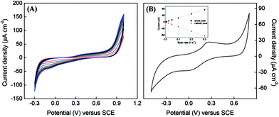
Cyclic voltammograms (CV) recorded during the polymerization of BBY are shown in Fig. 2A.
The positive potential limit of +1.0 V is required for the formation of radical cations, which initiate the polymerization process. With the increase in scan number the broad redox system in the potential region between −0.30 to +0.80 V that is related to the redox activity of poly(azo-BBY) becomes more evident, indicating continuous electrodeposition of the film. The polymerization mechanism is based on nitrogen–nitrogen coupling reactions (head-to-head coupling). In the nitrogen–nitrogen coupling mechanism, the first step is oxidation of the amine group (3-amine group in BBY) yielding a radical cation and/or dication in acid media11–13 at high positive potential values (Scheme 1 stage 1). The radical then undergoes the head-to-head coupling to form hydrazobenzene (stage 2) which can be further oxidized to produce new azobenzene species.
The CV recorded at FTO modified with poly(azo-Bismarck Y) (Fig. 2B) shows a quasi-reversible redox couple (Epa = 0.28 V; Epc = 0.00 V vs. SCE), which is attributed to oxidation and reduction of the azo group12,14,15 as follows:
The peak current scales linearly with the scan rate, as expected for a surface-confined reaction. CV enables the determination of the HOMO/LUMO energy levels from the onset potentials (EHOMO/LUMO = −(E[onset vs. NHE] + 4.4 eV)) of conjugated polymers,16 which were calculated to be −4.92 eV and −4.64 eV, respectively. Three thin films of polyBBY were prepared directly onto ITO applying 15, 50 and 100 cycles. The film thicknesses were calculated by background-corrected electric charge and film molar volume.17,18 Under the electropolymerization conditions described above, the thicknesses of the membrane were 0.0109 nm, 0.0204 nm and 0.0212 nm, respectively. The polymer film thickness is not proportional to the number of cycles and indicating a saturation of the electrode surface.
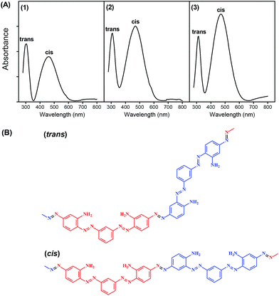
The optical properties of poly(azo-Bismarck Y) of different thicknesses electrodeposited on FTO (FTO/pBBY) electrode were analyzed by UV-Vis spectroscopy and are shown in Fig. 3A1–A3. The UV-Vis spectra of poly(azo-Bismarck Y) show two characteristic absorption bands at 302–312 nm and 460–471 nm.4–7 These two maxima are consistent with the expected presence of two different conjugation lengths in the twisted structure. The first band is related to the trans-form, which is the predominant form of the monomer in solution, while the second band is related to the cis-form of the azobenzene group (see Fig. 3B).
The absorption onset at 600 nm corresponds to an energy band gap of 2.05 eV attributable to the n → π* transition of the azo group.5 Such spectral features indicate a rigid conjugated planar structure with strong intramolecular interactions.6,19 The coplanarity of the cis isomer in the polymer allows a greater degree of resonance and, consequently, higher absorption intensity. The beginning of a broad absorption band at around 700 nm in the direction of longer wavelengths is associated with the polaronic state of the polymer, consistent with an average effective conjugation length in the polymer network that is too short to accommodate a polaron state.20 In the cis form, the conductivity through the π conjugated bonds of the polymer is facilitated and, therefore, film structures with prevalence of the cis form will be more conductive.
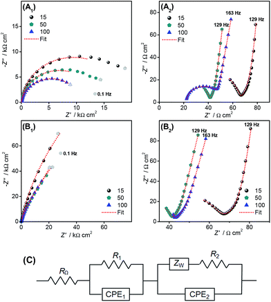
Impedance spectra gave information about the physical and interfacial properties of the FTO electrodes modified with pBBY as well as the electrochemical properties of the polymer film. Spectra obtained at −0.35 V and +0.30 V vs. SCE for FTO/pBBY of different thicknesses are shown as complex plane plots in Fig. 4A and B, respectively. The spectra were fitted to the electrical equivalent circuit presented in Fig. 4C and the fitting results are given in Table 1. Similar equivalent circuit was used to fit spectra obtained at electrodes modified with redox polymers.21,22
| E/V vs. SCE | No. of cycles | R1 Ω cm2 | CPE1 nF sα−1 cm−2 | α1 | ZW Ω s−0.5 cm2 | τ ms | αW | R2 kΩ cm2 | σ pS cm−1 | CPE2 μF sα−1 cm−2 | α2 |
|---|---|---|---|---|---|---|---|---|---|---|---|
| −0.35 | 15 | 63.2 | 27.7 | 0.95 | 31.9 | 0.35 | 0.42 | 14.6 | 74.7 | 24.3 | 0.98 |
| 50 | 38.9 | 26.9 | 0.99 | 17.5 | 0.35 | 0.40 | 11.9 | 168.1 | 27.8 | 0.95 | |
| 100 | 19.1 | 1450 | 0.99 | — | — | — | 9.6 | 229.2 | 35.4 | 0.93 | |
| +0.30 | 15 | 62.8 | 18.0 | 0.98 | 23.2 | 0.50 | 0.47 | 30.4 | 35.9 | 38.1 | 0.91 |
| 50 | 38.0 | 6.0 | 1.0 | 10.0 | 0.29 | 0.46 | 18.8 | 106.4 | 43.1 | 0.88 | |
| 100 | 39.0 | 0.5 | 1.0 | 14.5 | 0.30 | 0.42 | 15.2 | 144.7 | 52.3 | 0.87 |
The spectra for the reduced/oxidized state of poly(azo-Bismarck Y) obtained at −0.35/+0.30 V vs. SCE consist of a small radius semicircle at high frequencies (down to 100 Hz) (Fig. 4A2 and B2) followed by a second semicircle of larger radius in the low frequency region (below 100 Hz) (Fig. 4A1 and B1). The origin of the incomplete feature, modelled as part of a semi-circle, in the high frequency region can be associated with phenomena including uneven charge distribution on the electrode surface, and high mobility and number of charge carriers inside the polymer.23–25 At both applied potentials, the first RC combination is associated with the film-electrode substrate interface (R1 and CPE1), the values varying with film morphology and/or structure, and the second with the film itself and the polymer film–solution interface (R2 and CPE2) the values depending on polymer thickness as well as on oxygen solution content, at negative potentials (data not shown). The value of the charge transfer resistance R1 can be associated with the redox processes of the azo group at the polymer/electrode substrate interface, while R2 is related to charge transfer inside the polymer film network as well as between the poly(azo-Bismarck Y) and solution. All impedance spectra show a Warburg impedance at medium frequencies, attributed to finite diffusional processes inside the polymer, depending especially on film porosity. The CPE1 represents the capacitance values at the electrode/polymer interface while CPE2 corresponds to the capacitance of the film in contact with solution.
It can be seen from Table 1 that the charge transfer resistance R1 decreases with increase of film thickness at both applied potentials, probably due to the formation of island-like structures during the first 15 polymerisation cycles, which will overlap forming a complete uniform film layer, also indicated by the increase in α1 values which become 1.0 after 100 polymerisation cycles. The decrease of R2 is due to an increase in film conductivity with increasing number of polymerisation cycles, explained by the prevalence of more cis structure for thicker films, which enables better electronic conductivity, as seen in the UV-Vis spectra discussed. Moreover, at −0.35 V vs. SCE, R2 is lower than at +0.30 V, due to electron transfer processes occurring between the polymer and dissolved O2, being highly influenced by the O2 solution content. An increase in O2 content leads to a decrease of the R2 values. Considering R2 and the thickness values, an estimation of the conductivity of the films was made, and values are presented in Table 1. As observed, the conductivity increases with the number of polymerisation cycles, CPE2 values increase with the increase in film thickness, in this case the decrease of α2 values for thicker films implying more non-homogeneous structures. The films obtained during more polymerization cycles present lower charge transfer and film resistance and higher capacitance values, the electrical properties of the films being highly influenced by the polymer structure, the thicker polymer films with the cis structure prevalent being more conductive, important knowledge for the future design of devices incorporating these polymers. Further studies in the literature have demonstrated that cis-polymers may have higher conductivity than of trans-polymers.26–29
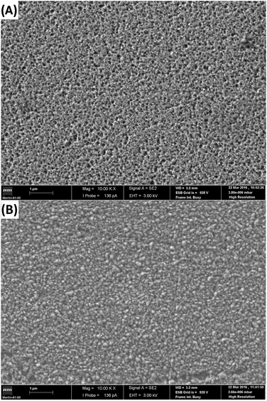
In general, these conclusions drawn from the electrochemical impedance data are backed up by morphologic investigations. Fig. 5A and B show magnifications of the polyBBY for two thicknesses electrodeposited on FTO electrode and clearly show the change of surface morphology. The SEM image of the thin film (50 polymerisation cycles) shows a surface less nano-structured with porous texture. The irregular pore distribution takes place due to the coexistence of different porous domains, thus resulting pore diameters between 10 nm and 90 nm. This porous morphology makes the polyBBY suited for the electrochemical applications as an electrode material in capacitors. Finally, and most excitingly, in image of the thicker film can be detected a dense layer, as shown in Fig. 5B, indicating the conjugated structure of the polymer on surface electrode, as determined from impedance spectra. It is apparent from these SEM images why the optical and impedance properties of the polymer are different in function of the thickness.
 | ||
| Fig. 5 SEM of polyBBY deposited on FTO electrode of different thicknesses obtained for (A) 50 cycles and (B) 100 polymerization cycles. Left scale bar is 1 μm. | ||
In summary, we have demonstrated the electrochemical and optical properties of poly(azo-Bismarck Y) are consistent with the formation of an electroactive conjugated network. Contrary to what was thought, the predominance of the more stable cis isomer in the polymer supports the conjugated structure. It is increasingly clear that the electronic properties of the polyBBy depend sensitively on the conformation of the polymer chains and the way the chains pack together in films. These results open new and interesting perspectives for the development of photoisomer materials with potential applications in sensors or catalysis. Further studies exploiting these characteristics are currently under way.
Experimental
The azo dye molecule 4,4′-[1,3-phenylenedi(E)-2,1-diazenediyl]di(1,3-benzenediamine) (BBY) was acquired from Sigma-Aldrich. A standard three-electrode cell was used for the preparation of the polymer and for electrochemical measurements. The working electrode was a glass slide covered with fluorine tin oxide (FTO) (Sigma-Aldrich) and the counter electrode was made from Pt wire. All potentials were measured relative to a saturated calomel electrode (SCE) as reference, with a μAUTOLAB type III galvanostat/potentiostat (Metrohm-Autolab, Netherlands).The electropolymerization of BBY was done on the FTO electrode (1.0 cm2) by potential cycling between −0.3 and +1.0 V vs. SCE at a scan rate of 100 mV s−1, for 15, 50 and 100 cycles in a solution containing 10 mmol L−1 BBY and 1.0 mol L−1 HCl. Before each experiment, the solution was deaerated using pure nitrogen gas.
Electrochemical impedance measurements were done with a PC-controlled Solartron Frequency Response Analyser coupled to Solartron 1286 Electrochemical Interface using ZPlot3.1 software. A sinusoidal voltage perturbation with amplitude of 10 mV rms was applied in the frequency range between 65 kHz and 0.1 Hz with 10 frequency steps per decade. EIS measurements were performed in 0.5 mol L−1 KCl solution containing 10 mmol L−1 HCl (pH 2.1). Fitting of the spectra with the equivalent electrical circuits was performed with ZView 2.4 software.
UV-Vis spectroscopy measurements were carried out using a Perkin Elmer Lambda 25 spectrophotometer to determine the characteristic absorption band and to monitor the growth of the azopolymeric film deposited onto the FTO electrode.
The surfaces of the samples were examined using an EVO 50EP (Carl Zeiss SMT AG, Germany) scanning electron microscope. All observations were carried out with a secondary electron (SE) detector in high-vacuum mode at 15 kV accelerating voltage.
Acknowledgements
The authors acknowledge FAPESP (2005/01296-4) and CNPq (234256/2014-1) for financial support. M. M. B. thanks FCT for a postdoctoral fellowship SFRH/BPD/72656/2010.Notes and references
- L. Z. Zhang, T. B. Yang, L. Shen, Y. J. Fang, L. Dang, N. J. Zhou, X. G. Guo, Z. R. Hong, Y. Yang, H. B. Wu, J. S. Huang and Y. Y. Liang, Adv. Mater., 2015, 27, 6496-+ CrossRef CAS PubMed.
- S. Takahashi, T. Mashio, N. Horibe, K. Akizuki and A. Ohma, ChemElectroChem, 2015, 2, 1560–1567 CrossRef CAS.
- A. K. Bakhshi, A. Kaur and V. Arora, Indian J. Chem., Sect. A: Inorg., Bio-inorg., Phys., Theor. Anal. Chem., 2012, 51, 57–68 Search PubMed.
- J. Tan, A. D. Li, X. Z. Fan, W. C. Liu, Z. X. Xu, Y. Lin, H. T. Wang, D. Wu and N. B. Ming, Phys. Status Solidi A, 2007, 204, 1114–1122 CrossRef CAS.
- E. Merino and M. Ribagorda, Beilstein J. Org. Chem., 2012, 8, 1071–1090 CrossRef CAS PubMed.
- M. Haro, I. Gascon, R. Aroca, M. C. Lopez and F. M. Royo, J. Colloid Interface Sci., 2008, 319, 277–286 CrossRef CAS PubMed.
- E. Kibena, U. Maorg, L. Matisen, P. Sulamagi and K. Tammeveski, J. Electroanal. Chem., 2012, 686, 46–53 CrossRef CAS.
- T. Ikeda and O. Tsutsumi, Science, 1995, 268, 1873–1875 CAS.
- Y. R. Leroux and P. Hapiot, Electrochem. Commun., 2013, 33, 107–110 CrossRef CAS.
- J. A. Delaire and K. Nakatani, Chem. Rev., 2000, 100, 1817–1845 CrossRef CAS PubMed.
- C. Yao, H. Sun, H. F. Fu and Z. C. Tan, Electrochim. Acta, 2015, 156, 163–170 CrossRef CAS.
- S. A. Kumar, C. F. Tang and S. M. Chen, Talanta, 2008, 74, 860–866 CrossRef CAS PubMed.
- H. H. Rehan, J. Appl. Electrochem., 2000, 30, 945–951 CrossRef CAS.
- H. Yao, Y. Y. Sun, X. H. Lin, Y. H. Tang and L. Y. Huang, Electrochim. Acta, 2007, 52, 6165–6171 CrossRef CAS.
- A. Eriksson and L. Nyholm, Electrochim. Acta, 1999, 44, 4029–4040 CrossRef CAS.
- C. M. Cardona, W. Li, A. E. Kaifer, D. Stockdale and G. C. Bazan, Adv. Mater., 2011, 23, 2367–2371 CrossRef CAS PubMed.
- M. Sharp, M. Petersson and K. Edstrom, J. Electroanal. Chem., 1980, 109, 271–288 CrossRef CAS.
- T. R. L. Dadamos and M. F. S. Teixeira, Electrochim. Acta, 2009, 54, 4552–4558 CrossRef CAS.
- O. V. Yaroshchuk, M. Dumont, Y. A. Zakrevskyy, T. V. Bidna and J. Lindau, J. Phys. Chem. B, 2004, 108, 4647–4658 CrossRef CAS.
- F. Piron, P. Leriche, G. Mabon, I. Grosu and J. Roncali, Electrochem. Commun., 2008, 10, 1427–1430 CrossRef CAS.
- M. M. Barsan, E. M. Pinto and C. M. A. Brett, Electrochim. Acta, 2008, 53, 3973–3982 CrossRef CAS.
- M. Dubois and D. Billaud, Electrochim. Acta, 2002, 47, 4459–4466 CrossRef CAS.
- P. A. Christensen and A. Hamnett, Electrochim. Acta, 1991, 36, 1263–1286 CrossRef CAS.
- M. F. Mathias and O. Haas, J. Phys. Chem., 1992, 96, 3174–3182 CrossRef CAS.
- X. Y. Zhao, J. B. Zang, Y. H. Wang, L. Y. Bian and J. K. Yu, Electrochem. Commun., 2009, 11, 1297–1300 CrossRef CAS.
- H. Shirakawa, E. J. Louis, A. G. Macdiarmid, C. K. Chiang and A. J. Heeger, Chem. Commun., 1977, 578–580 RSC.
- K. Kimura, T. Suzuki and M. Yokoyama, J. Phys. Chem., 1990, 94, 6090–6093 CrossRef CAS.
- S. Shinkai, T. Yoshida, O. Manabe and Y. Fuchita, J. Chem. Soc., Perkin Trans. 1, 1988, 1431–1437 RSC.
- T. Mosciatti, S. Bonacchi, M. Gobbi, L. Ferlauto, F. Liscio, L. Giorgini, E. Orgiu and P. Samori, ACS Appl. Mater. Interfaces, 2016, 8, 6563–6569 CAS.
| This journal is © The Royal Society of Chemistry 2016 |


