Visible light responsive Fe–ZnS/nickel foam photocatalyst with enhanced photocatalytic activity and stability

Yanei Xueab, Rongjun Sua, Guangshan Zhangb, Qiao Wangb, Peng Wangb, Wen Zhangc and Zhihong Wang*d
aDepartment of Life Science, Environmental Science Researching Center, Harbin University of Commerce, Harbin 150076, China
bState Key Laboratory of Urban Water Resource and Environment, School of Municipal and Environmental Engineering, Harbin Institute of Technology, Harbin 150090, China. E-mail: gszhanghit@gmail.com
cJohn A. Reif, Jr., Department of Civil & Environmental Engineering, New Jersey Institute of Technology, Newark, NJ 07102, USA
dDepartment of Physics, Harbin Institute of Technology, Harbin 150090, China. E-mail: wangzhihong@hit.edu.cn

Received 10th August 2016 , Accepted 24th September 2016

First published on 26th September 2016


Abstract

ZnFeS photocatalysts were successfully decorated on nickel foam to form a ZnFeS/nickel foam composite photocatalyst. The ZnFeS/nickel foam not only prevented the photocorrosion-induced release of Zn and Fe ions, but also increased visible light absorption that promoted its charge separation and catalytic activity. The novel photocatalyst displayed a high biphenol A (BPA) removal of 82% within 120 min and excellent stability, which excels other common catalysts for BPA degradation.

Solar energy is the most abundant clean energy source nowadays. Extensive research has been devoted to utilization of solar energy for green and efficient pollutant degradation.1–3 In this field, photocatalytic systems have attracted great interest as the most promising way to remove water pollutants and particularly those refractory emerging contaminants.4–6 The effective utilization of catalysts and the control of catalyst activity and stability are key factors for the success of photocatalytic processes.

To enhance the photocatalytic activity in the visible light region for the degradation of water pollutants, various approaches have been developed, such as surface modification,7 structure optimization,8 and doping with metal or non-metal elements, etc.9,10 For example, a common semiconductor photocatalyst, ZnS, can produce photoelectrons and holes in a rapid speed after irradiated by UV light, and the holes and excited electrons have a strong power to oxidize organic molecules due to their transformation into various radicals.11–13 After doping Fe ion, the energy band structure of ZnS can be modified to allow greater absorption of visible light energy and thus substantially increase its photocatalytic activity. Moreover, this hybrid photocatalyst (ZnFeS) exhibited a good stability as reported in our previous work.14 A common practice in the operation of photocatalytic systems is to immobilize catalytic particles on substrate surfaces to retain and separate them from the water flow that is being treated. The substrate surfaces for loading photocatalyst on are typically non-reactive, highly porous to render high surface areas, and low cost. Recently, the nickel foam has been identified as an effective material to act as the support medium for powdery photocatalyst in water treatment.15,16 Nickel foam is a commercial material with high electronic conductivity with 3D structure, large porosity and surface areas. However, the combination of sulfide photocatalyst powders and nickel foam to produce hybrid photocatalysts for organic pollutant degradation has not been reported. Moreover, considering the high electronic conductivity of nickel foam, the introduction of nickel foam is expected to promote charge separation and extend the absorption capability of sulfide photocatalysts toward visible light, which potentially facilitates the solar energy utilization.17–19

Herein, the ZnFeS photocatalyst was synthesized by a microwave irradiation method as reported in our previous work,20 and then decorated onto a nickel foam by coupling method to form a novel composite material (see details in Section S1 of ESI).21 The photocatalytic activities of the prepared material were investigated through the degradation of BPA (a model emerging water contaminant) under visible light irradiation. The characteristics of the composite material was studied in detail. The photocatalytic activity and stability of the composite material for BPA degradation in water were analyzed. Moreover, the synergistic effects of ZnFeS and nickel foam were discussed as well.

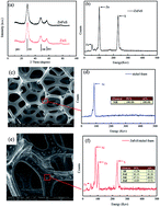
Fig. 1(a) and (b) show the elementary composition of the synthesized ZnFeS powder analysed by XRD and EDX, respectively. The XRD pattern of ZnFeS is anastomosed with ZnS of cubic spinel structure (JCPDS no. 5-566),22 which indicates that the catalyst ZnFeS may have similar crystal structures of ZnS. A small amount of Fe in the ZnS crystal lattice may have replaced Zn and a composite metal sulfide (ZnFeS) was formed.23 The EDS result of ZnFeS indicates the presence of Fe, Zn, and S in the catalyst. Raw nickel foam substrate and ZnFeS/nickel foam composite catalyst were examined by SEM, as shown in Fig. 1(c) and (e). The ZnFeS catalysts synthesized by microwave irradiation method have a compact dense morphology with obvious concave and convex as shown in Fig. S2 of ESI. The raw nickel foam substrate has a porous framework and smooth surface. EDS confirms that the foam is composed of pure Ni in Fig. 1(d). After decorating ZnFeS, some particles were observed that uniformly deposited on the surface of nickel foam in Fig. 1(e). EDS analysis shows that Zn, S, Fe and Ni elements co-existed in the ZnFeS/nickel foam composite catalyst in Fig. 1(f). These results also reveal that the surface structure of nickel foam remained unchanged after decoration of catalyst.


image file: c6ra20187c-f1.tif
Fig. 1 (a) XRD patterns and (b) EDS images of ZnFeS, (c) SEM and (d) EDS images of nickel foam, (e) SEM and (f) EDS images of ZnFeS/nickel foam.

The photodegradation of BPA was tested for 120 min under visible light irradiation (500 W xenon lamp, 6.1 mW cm−2) in a cylindrical reactor (Fig. S3 of ESI). As shown in Fig. 2(a), the raw nickel foam did not cause any BPA degradation, while the removal rate reached 15% only using ZnFeS after 120 min (4.69 × 10⁻⁵ mg-BPA per mg-catalyst per min). After decorating ZnFeS onto nickel foam, the loading amount of ZnFeS was 2.2 wt% (see details in Section S2 of ESI). The available amount of ZnFeS catalyst on nickel foam was 0.08 g in the same photocatalytic reactions, which was consistent with the tests using ZnFeS only. Furtherly, the BPA removal using the ZnFeS/nickel foam exceeded over 82%, indicative of a higher photocatalytic activity (1.28 × 10⁻⁴ mg-BPA per mg-catalyst per min).


image file: c6ra20187c-f2.tif
Fig. 2 BPA removal for different photocatalysts (a), the generation of hydroxyl radicals in the degradation process of BPA (b), and UV-Vis spectra of the samples (c).

By contrast, the photocatalytic degradation rates of BPA were reported be 2.55 × 10⁻⁵ mg-BPA per mg-catalyst per min in the photocatalysis of 3 wt% Ce–ZnO catalyst24 and 1.11 × 10⁻⁴ per mg-catalyst in the photocatalysis of Pd/mpg-C3N4 catalyst25 under similar visible light or UV irradiation, which highlighted the unique synergy of hybridized ZnFeS/Ni catalysts. To further evaluate the function of nickel foam, activated carbon (abbreviated as AC), which is also a widely used catalyst substrate,26,27 was employed as a substrate for ZnFeS photocatalyst. Consecutive photocatalytic degradation reactions of BPA with the ZnFeS/AC composite catalyst were carried out under the same conditions (e.g., the amount of the catalyst was the same as ZnFeS/nickel foam). Fig. 2(a) shows that the introduction of AC does not enhance the photocatalytic degradation of BPA as the porous Ni foam substrate did. Fig. 2(b) shows the generation of hydroxyl radicals (·OH) in the degradation process of BPA, using terephthalic acid as the ·OH-specific scavenger agent, which was detected by fluorescence spectrophotometry.28 It is obvious that the highest amount of ·OH generated in the ZnFeS/Ni system could explain the excellent degradation activity toward BPA.

Fig. 2(c) displays the UV-Vis spectra of ZnFeS, ZnFeS/nickel foam and raw nickel foam. ZnS had no light absorption in visible-light region,29 whereas ZnFeS and ZnFeS/nickel foam photocatalysts were both responsive in visible absorption region. The edge of absorption band of ZnFeS/nickel foam had a slight red-shift, which better enables the utilization capacity of ZnFeS/nickel foam to visible light.

The photocatalytic stability of ZnFeS and ZnFeS/nickel foam composite material under visible light the are evaluated by reusing the photocatalyst in the BPA degradation. Fig. S2 in ESI shows the components of the photocatalytic reactor. Fig. 3(a) shows that the BPA removal rate was relatively stable (above 80%) with slight decline after seven cycles. On the contrary, the degradation rate with ZnFeS catalyst declined appreciably in every cycle. Clearly, the decoration of ZnFeS catalyst onto nickel foam enhanced the overall stability and longevity. Furthermore, the dissolution of ZnFeS and ZnFeS/nickel foam was assessed by measuring the time-resolved concentrations of dissolved metal ions (Zn and Fe) in the solutions in the course of photocatalytic reactions by ICP-MS. In the photocatalysis, no significant Ni in the reaction solution was detected. Fig. 3(b) and (c) show that the released concentrations of Fe2+ and Zn2+ for ZnFeS/nickel foam material were both remarkably lower (∼half of) than the observed levels for pure ZnFeS catalyst. The possible reason is that after deposition onto nickel foam the ZnFeS catalyst had less surface interactions with water and thus reduced the photocorrosion rate. The dissolved Zn2+ within 120 min was under 1.0 mg L−1, which meet the Zn standard of Integrated Wastewater Discharge Standard in China.


image file: c6ra20187c-f3.tif
Fig. 3 BPA degradation over 7 reaction cycles by ZnFeS and ZnFeS/nickel foam catalyst (a), the concentration of dissolved metal ions of ZnFeS (b) and ZnFeS/nickel foam (c) in the reaction solution under visible light irradiation.

It has been recently proposed that in some photocatalytic reactions in the presence of photocatalysts such as TiO2 and ZnO, the element of Ni plays a significant role in promoting catalytic activity.15,16,30,31 The function of the trace metal dopant not only helps reduce the recombination of charge-carriers by trapping electrons, but also acts as a recombination center of atomic hydrogen (H·) coming from catalysts surface to form hydrogen. Luna et al.30 synthesized Au and Ni nanoparticles by radiolysis on TiO2 (commercial P25) surfaces at various metal contents and showed that the surface modification of TiO2 by Au and Ni nanoparticles led to a high photocatalytic activity for hydrogen evolution from aqueous methanol solution. Thein et al.31 demonstrated that the photocatalytic activity of ZnO nanoparticles could be improved after decoration by Ni particles. The model dye compound, Rh B, in the water solution was photodegradated in the presence of ZnO nanorods decorated with Ni under UV irradiation.

Based on our experiment results and previous reports,30,32 the photocatalytic degradation of BPA by the ZnFeS/nickel foam composite material under visible light irradiation can be explained by the following eqn (1)–(4) and possible pathways in Fig. 4.

 
ZnFeS/nickel foam + hv → ecb + hvb+ (1)
 
O2 + ecb → O2· (2)
 
H2O + hvb+ → H+ + ·OH (3)
 
O2·/·OH + BPA → CO2 + H2O (4)


image file: c6ra20187c-f4.tif
Fig. 4 Suggested degradation pathways of BPA by ZnFeS/nickel foam.

Under visible light irradiation, photo-generated electrons and holes are generated on the surface of ZnFeS photocatalyst.14,22 Nickel foam may efficiently shuttle the photoexcited electrons and promote the electron transfer (charge separation) owing to its excellent electronic conductivity. The electrons are captured by dissolved O2 adsorbed on the surface of nickel foam to form superoxide anion (O2·), which is another powerful radical capable of decomposing organic pollutants. The holes react with OH and H2O to form ·OH, which can nonselectively oxidize and destroy almost all organic molecules. The potential synergistic roles of nickel foam in the hybrid photocatalytic reactions are multifold: (1) the multi-layer structure of nickel foam could provide high surface areas and reaction sites of catalysts as they were uniformly distributed on nickel substrate surface and avoided particle aggregation as opposed to suspended particles in the solid particle solution; (2) the porous structure of nickel foam may also improve the local diffusion and mass transfer of BPA toward the surface of photocatalyst, which is critical as photocatalytic reactions usually occur on or near the surface of the photocatalyst.33

In summary, we developed a novel nickel foam-supported ZnFeS catalyst by a combination of microwave irradiation synthesis and coupling method and further demonstrated a higher photocatalytic activity and excellent cycling stability. The BPA removal rate reached 82% within 120 min (1.28 × 10⁻⁴ mg-BPA per mg-catalyst per min) under visible light irradiation and remained active and stable in the removal rate of above 80% after seven reaction cycles (14 h). The obtained results indicate that the nickel foam not only served as a support material but also improved the photocatalytic activity through providing high surface areas, extending visible light adsorption, improving charge separation and pollutant degradation. The unique features and synergy we observed from this hybridized ZnFeS/Ni photocatalyst may provide new insight into the design, high-performance, durable and recoverable photocatalytic systems for sustainable water and wastewater treatment as well as other photocatalytic applications.

Acknowledgements

This work was financially supported by the Open Project of State Key Laboratory of Urban Water Resource and Environment, Harbin Institute of Technology (QA201610-01), the 9th Special Financial Grant from the China Postdoctoral Science Foundation (2016T90304) and the Provincial Natural Science Foundation of Heilongjiang (B2015025).

Notes and references

  1. Y. Lu, K. Zhao, Y. Zhao, S. Zhu, X. Yuan, M. Huo, Y. Zhang and Y. Qiu, Colloids Surf., A, 2015, 481, 252–260 CrossRef CAS .
  2. L. Yang, W. Duan, H. Jiang, S. Luo and Y. Luo, Mater. Res. Bull., 2015, 70, 129–136 CrossRef CAS .
  3. L. Cheng, Y. Wang, D. Huang, T. Nguyen, Y. Jiang, H. Yu, N. Ding, G. Ding and Z. Jiao, Mater. Res. Bull., 2015, 61, 409–414 CrossRef CAS .
  4. Y. H. Tan, P. S. Goh and A. F. Ismail, Int. Biodeterior. Biodegrad., 2015, 102, 346–352 CrossRef CAS .
  5. S. Ramasundaram, A. Son, M. G. Seid, S. Shim, S. H. Lee, Y. C. Chung, C. Lee, J. Lee and S. W. Hong, J. Hazard. Mater., 2015, 285, 267–276 CrossRef CAS PubMed .
  6. Z. T. Hu, J. Liu, X. Yan, W. D. Oh and T. T. Lim, Chem. Eng. J., 2015, 262, 1022–1032 CrossRef CAS .
  7. J. Liu, P. Liu, X. Zhang, P. Lu, X. Zhang and M. Zhang, Chem. Eng. J., 2016, 295, 73–79 CrossRef CAS .
  8. N. A. Badli, R. Ali, W. A. Wan Abu Bakar and L. Yuliati, Arabian J. Chem., 2016 DOI:10.1016/j.arabjc.2016.02.011 .
  9. N. Guy, S. Cakar and M. Ozacar, J. Colloid Interface Sci., 2016, 466, 128–137 CrossRef CAS PubMed .
  10. C. J. Chang, K. L. Huang, J. K. Chen, K. W. Chu and M. H. Hsu, J. Taiwan Inst. Chem. Eng., 2015, 55, 82–89 CrossRef CAS .
  11. E. Hong, D. Kim and J. H. Kim, J. Ind. Eng. Chem., 2014, 20, 3869–3874 CrossRef CAS .
  12. V. Vaiano, O. Sacco, D. Sannino and P. Ciambelli, J. Cleaner Prod., 2015, 100, 208–211 CrossRef CAS .
  13. Y. C. Weng and Y. D. Chou, Electrochim. Acta, 2015, 153, 416–425 CrossRef CAS .
  14. G. S. Zhang, Y. N. Xue, R. Su, Q. Wang, W. Zhang, Y. Yuan and P. Wang, J. Photochem. Photobiol., A, 2016 DOI:10.1016/j.jphotochem.2016.1006.1004 .
  15. H. Hu, W. J. Xiao, J. Yuan, J. W. Shi, M. X. Chen and W. F. Shangguan, J. Environ. Sci., 2007, 19, 80–85 CrossRef CAS .
  16. J. Yuan, H. Hu, M. Chen, J. Shi and W. F. Shangguan, Catal. Today, 2008, 139, 140–145 CrossRef CAS .
  17. J. Meng, F. Li, Y. Hu, L. Xu, Z. Sun and J. Liu, Mater. Res. Bull., 2013, 48, 2111–2116 CrossRef CAS .
  18. D. Li, J. Xie, Y. Zhang, R. Qiao, S. Li and Z. Li, J. Alloys Compd., 2015, 646, 978–982 CrossRef CAS .
  19. K. M. Lee, C. W. Lai, K. S. Ngai and J. C. Juan, Water Res., 2016, 88, 428–448 CrossRef CAS PubMed .
  20. K. J. Lee, B. H. Jun, J. Choi, Y. Lee, J. Joung and Y. S. Oh, Nanotechnology, 2007, 18, 335601 CrossRef .
  21. X. Zhou, X. N. Zhang, X. B. Feng, J. Zhou and S. Q. Zhou, Dyes Pigm., 2016, 125, 375–383 CrossRef CAS .
  22. H. R. Rajabi, O. Khani, M. Shamsipur and V. Vatanpour, J. Hazard. Mater., 2013, 250–251, 370–378 CrossRef CAS PubMed .
  23. R. Juškėnas, G. Niaura, Z. Mockus, S. Kanapeckaitė, R. Giraitis, R. Kondrotas, A. Naujokaitis, G. Stalnionis, V. Pakštas and V. Karpavičienė, J. Alloys Compd., 2016, 655, 281–289 CrossRef .
  24. M. Kamaraj, K. S. Ranjith, R. Sivaraj, R. R. T. Kumar and H. Abdul Salam, J. Environ. Sci., 2014, 26, 2362–2368 CrossRef CAS PubMed .
  25. C. Chang, Y. Fu, M. Hu, C. Wang, G. Shan and L. Zhu, Appl. Catal., B, 2013, 142–143, 553–560 CrossRef CAS .
  26. J. W. Shi, Chem. Eng. J., 2009, 151, 241–246 CrossRef CAS .
  27. H. Nakagawa, S. Takagi and J. Maekawa, Chem. Eng. J., 2016, 296, 398–405 CrossRef CAS .
  28. W. Q. Pan, G. S. Zhang, T. Zheng and P. Wang, RSC Adv., 2015, 5, 27043–27051 RSC .
  29. G. S. Zhang, W. Zhang, D. Minakata, P. Wang, Y. S. Chen and J. Crittenden, Int. J. Energy Res., 2014, 38, 1513–1521 CrossRef CAS .
  30. A. L. Luna, E. Novoseltceva, E. Louarn, P. Beaunier, E. Kowalska, B. Ohtani, M. A. Valenzuela, H. Remita and C. Colbeau-Justin, Appl. Catal., B, 2016, 191, 18–28 CrossRef CAS .
  31. M. T. Thein, S.-Y. Pung, A. Aziz and M. Itoh, J. Taiwan Inst. Chem. Eng., 2016, 61, 156–165 CrossRef CAS .
  32. H. Hu, W. J. Xiao, J. Yuan, J. W. Shi, D. N. He and W. F. Shangguan, J. Sol–Gel Sci. Technol., 2007, 45, 1–8 CrossRef .
  33. L. A. Tercero Espinoza, M. Neamtu and F. H. Frimmel, Water Res., 2007, 41, 4479–4487 CrossRef CAS PubMed .

Footnote

Electronic supplementary information (ESI) available. See DOI: 10.1039/c6ra20187c

This journal is © The Royal Society of Chemistry 2016