DOI:
10.1039/C6RA20095H
(Paper)
RSC Adv., 2016,
6, 84658-84671
Role of (3-aminopropyl)tri alkoxysilanes in grafting of chlorosulphonic acid immobilized magnetic nanoparticles and their application as heterogeneous catalysts for the green synthesis of α-aminonitriles†
Received
9th August 2016
, Accepted 23rd August 2016
First published on 23rd August 2016
Abstract
The surface modification of SiO2 coated Fe3O4 nanoparticles by grafting silane coupling agents is a highly significant approach to enhancing the interface interaction between the inorganic magnetic core and the organic functionality to be anchored. However, the effect of the grafted molecular structure of silane, utilizing different silane alkoxy groups, has been seldom investigated on the organic–inorganic hybrid magnetic heterogeneous catalysts. The silanization was carried out on the surface of SiO2 coated Fe3O4 nanoparticles using two different trialkoxy silanes, i.e., 3-aminopropyltriethoxysilane (APTES) and 3-aminopropyltrimethoxysilane (APMES). The effect of the alkoxy silane structure anchored to the surface of silica functionalized Fe3O4 nanoparticles on their surface area and pore volume has been analyzed by BET analyzer. The silane functionalization using APTES leads to higher surface area and pore volume than APTMS. Further, chlorosulphonic acid was immobilized on both the APTES and APTMS functionalized SiO2@Fe3O4 nanoparticles named (AE and AM), and their role as magnetically separable heterogeneous catalyst for the one pot synthesis of α-aminonitriles using water as solvent was successfully carried out. The chlorofunctionalized nanoparticles, which utilized APTES as the silanizing agent, showed better catalytic activity than APTMS in terms of reaction time and yield. The presented protocol is a water based synthesis involving room temperature conditions, along with reusability and recyclability of the catalyst. The characterization of the synthesized catalysts was carried out by using different techniques, such as FT-IR, XRD, TEM, BET, XPS, VSM and TGA-DTA.
1. Introduction
Magnetic nanoparticles have received much attention in academics, research and industrial fields, due to their properties, which include high surface area, high degree of chemical stability, high catalytic activity, non-swelling in organic solvents,1–3 easy recovery using an external magnet, reusability,4 regular shape, uniform size, low cost of production, non toxicity and biocompatibility.5 They are also used in other fields, such as sealing, oscillation damping, information storage, electronic devices, etc.5 Under biomedical applications they are used as biosensors,6 contrast agents in magnetic resonance imaging (MRI),7 localizers in therapeutic hyperthermia,8 drug delivery systems, etc.9 A number of methods of preparation of magnetic nanoparticles have been reported, including co-precipitation, solvothermal/hydrothermal synthesis, micro emulsion and thermal decomposition. Due to its simplicity and the formation of monodisperse nanoparticles, the co-precipitation method is declared one of the best methods of synthesis.10a
Under the catalytic system, a large number of nanocatalysts are used as heterogeneous catalysts in many organic synthetic transformation reactions. These have many advantages over the conventional catalyst, like their nanoscale size, possessing a high surface area of active components, which in turn increases the contact between the reactants and the catalyst, which results in a high reaction rate, and their high surface to volume ratio increases the catalytic activity and accessibility of the catalyst. However, the nanoscale size of heterogeneous catalysts makes their recovery from the reaction mixture difficult; sometimes it is more difficult to isolate or recycle the catalyst by conventional filtration and centrifugation methods. This limitation obstructs the economic and sustainable growth of these kinds of the protocols. Therefore, there is a demand for some alternatives to overcome these problems and reuse or recycle the catalysts in a highly efficient manner. Magnetic nanoparticles are the suitable alternatives and are extensively explored. Their paramagnetic nature allows for their easy separation from the reaction mixture by using an external magnet, which in turn increases the recyclability and reusability. The remarkable catalyst recovery, their non solubility in the reaction medium, green synthesis protocol, minimum waste production and minimum work up procedure are the important characteristics that make them more sustainable.10b–e
Further application of the magnetic nanoparticles as support has been reported. Super-paramagnetic iron oxide nanoparticles have been studied as magnetic support for the nano catalytic system. Silica coating on magnetic nanoparticles enhances their dispersibility in liquid medium by stopping the dipole attractions between the nanoparticles, improves chemical stability, enhances their performance, protects from leaching in an acidic environment, provides high hydrothermal stability, protects from the further oxidation of bare magnetic nanoparticles, enhances the textural properties of magnetic nanoparticles and protects against toxicity. The presence of a large number of silanol groups on their surface facilitates easy further functionalization with different organic moieties, provides high surface area, which enhances the catalytic loading and activity, and also prevents the unwanted interaction between the core, magnetic nanoparticles and the additional agents linked to the silica surface. All these properties render the inert coating of silica as a solid support for many organic and inorganic moieties.10f–i (3-Aminopropyl)-trialkoxysilanes are widely used as silanizing agents for the surface modification of the nanoparticles, as their terminal amine groups can facilitate the further functionalization of the nanoparticles.
The reaction between aldehyde, amine and cyanide sources gives rise to the formation of α-aminonitrile,11 and is known as the Strecker reaction;12,13 its reliability, versatility of the resulting products and easy availability of the starting materials are some reasons behind its use in the formation of the large scale production of amino acids, herbicides and chelating agents.14 Further, α-aminonitriles are the important intermediates for the formation of amino acids,15 and important synthons of organic chemistry11 such as nitrogen containing heterocycles16 like imidazole and thiadiazole, other biologically important molecules like saframycin A, having anti tumor activity, or phthalascidi,17 manzacidin A, prasugrel, clopidogrel and short acting opioid analgesics.18 They are also considered as valuable intermediates in the formation of different diamines, amides and pharmaceuticals.11 α-Amino acids have immense biological and economic importance due to their widespread applications in the fields of chemistry and biology. They are also useful as the chiral building blocks in the pharmaceutical industry19 and as key precursors for the preparation of proteins.11 Recently, by using this strategy, the synthesis of the hepatitis C virus NS3 serine protease inhibitors,20 (±)-phthalascidin 622
21 and novel boron containing retinoids22 have been reported.
In general, the Strecker reaction involves the nucleophilic addition of the cyanide source to the imine.12 The common cyanide sources that have been used so far are HCN,11 KCN,23a (EtO)2POCN,23b Et2AlCN,23c BuSnCN.23d All these mentioned cyanide sources are hazardous, toxic in nature, require harsh reaction conditions, and special handling and care is required during their use.24 It has been reported that TMSCN, due to its properties like easy handling, effective and safe use, is one of the most promising cyanide sources.25 So far, many Lewis acids or Bronsted acids like Fe(Cp)2PF6,26a InCl3,26b RhI3,26c Cu(OTf)2,14 I2,26d BiCl3,26e La(NO3)3·6H2O, GdCl3·6H2O,26f NiCl2,26g Ga(OTf)3,26h GaCl3,26i CeCl3,26j Pr(OTf)3,26k RuCl3,26l FeCl3
26m catalysts, etc. have been reported, which homogeneously catalyze this reaction, but leave behind the limitations of costly, toxic catalytic systems, longer reaction times and difficult separation work up.26n Therefore, there arises the use of heterogeneous catalysts that overcome these problems. Further, supported heterogeneous catalysts have advantages such as simple separation method, minimization of waste, simple recovery, recyclability, reusability and lower contamination of the products.27–29 Chlorosulphonic acid has been used in a wide variety of applications like alkylation, cyclization, polymerization, halogenations and rearrangement reactions;29b however, its direct use in water is not feasible, as it causes the formation of HCl and H2SO4. Therefore, this encouraged us to immobilize it on another support, which promotes its use in various promising applications of sulphamic acid as an acidic catalyst in reactions like acetalization, esterification, acetylation of phenols and alcohols, nitrile formation as a chemoselective catalyst in the transesterification of β-ketoesters, Beckmann rearrangement, etc.29c
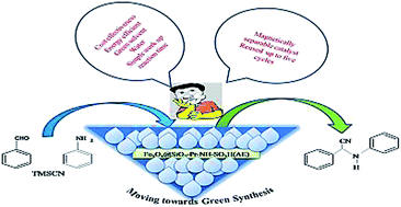
In the present study, SiO2@Fe3O4 nanoparticles have been synthesized by Stober's method. Further silanization on the surface of hydroxylated SiO2@Fe3O4 nanoparticles was carried out, utilizing two different trialkoxy silanes, i.e., 3-aminopropyltriethoxysilane (APTES) and 3-aminopropyltrimethoxysilane (APTMS). The APTES functionalized SiO2@Fe3O4 nanoparticles have obtained higher surface area and pore volume (6.3891 m2 g−1 and 6.03 × 10⁻³ cm3 g−1) than APTMS (1.3220 m2 g−1 and 1.4 × 10⁻³ cm3 g−1). Further, the chlorosulphonic acid was immobilized on both NH2-Pr-SiO2@Fe3O4 nanoparticles generated by two different alkoxy silanes, i.e., APTES and APTMS obtained as Fe3O4@SiO2-Pr-NH-SO3H (AE) and Fe3O4@SiO2-Pr-NH-SO3H (AM) nanoparticles. Further, they have been used in the synthesis of α-aminonitriles via coupling of three components, aldehyde, aniline and trimethylsilylcyanide, by using water (as a green solvent) as the reaction medium. Comparison of reaction time and yield of α-aminonitriles has also been carried out. Best results were obtained with AE, which encouraged us to focus on AE nanoparticles. Therefore, in continuation of our previous work on catalysis,10h a simple and environmentally friendly work up procedure for the formation of product in high yields has been developed. All these steps make this protocol eco friendly, cost effective, simple and efficient in nature.
2. Results and discussion
2.1 Characterization of the as prepared catalyst
FT-IR. In Fig. 1 the peaks of Fe3O4 nanoparticles were found to be below 700 cm−1, the peak at 600 cm−1 was attributed to the Fe–O vibrations; O–H deformed vibrations were found near 1646 cm−1 and O–H stretching vibrations at 3132 cm−1. The FT-IR spectra of Fe3O4@SiO2, consist of the peaks at 447 cm−1, 954 cm−1 and a sharp peak at 1061 cm−1, which are due to the asymmetric stretching vibration, symmetric vibration and bending vibration of the all Si–O–Si groups. Similarly the O–H stretching vibration near 3100–3400 cm−1 and the O–H deformed vibration near 1630–1646 cm−1 were present in both cases.30 The decrease in the intensity of the peak at around 600 cm−1 confirmed the coating of silica on the Fe3O4 nanoparticles. In the FT-IR spectra of Fe3O4@SiO2-Pr-NH2 (APTES) and Fe3O4@SiO2-Pr-NH2 (APTMS), the introduction of APTES and APTMS on Fe3O4@SiO2 was confirmed by the Si–O peak at 1117 cm−1 and 1124 cm−1 and the broad N–H peak at around 3245 cm−1 and 3358 cm−1, respectively. Further, the presence of the propyl group was confirmed by the C–H peaks at 2955 cm−1, 2822 cm−1 and 2904 cm−1, 2890 cm−1 for APTES and APTMS, respectively.35 In the FT-IR spectra of AE, the introduction of the sulphonyl moieties was confirmed by the bands at 1125 cm−1 and 1250 cm−1 and for AM, at 1147 cm−1 and 1280 cm−1.
 |
| Fig. 1 Comparative study of Fourier transform infrared (FT-IR) spectra of Fe3O4 nanoparticles (MNPs), Fe3O4@SiO2, Fe3O4@SiO2-Pr-NH2 (APTMS), Fe3O4@SiO2-Pr-NH2 (APTES), AM and AE. | |
Surface area and pore volume analysis. BET methodology was used extensively for the estimation of surface area and pore volume of the materials, as both are the important parameters used for the determination of catalytic activity of the catalyst, as shown in Fig. 2.
 |
| Fig. 2 (a) Surface area plot of AM, (b) pore volume plot of AM, (c) surface area plot of AE, (d) pore volume plot of AE. | |
Here, we studied the effect of surface area due to the grafting of APTES and APTMS on Fe3O4@SiO2 nanoparticles, followed by chlorosulphonic acid immobilization. The surface area was calculated by using the BET equation.31a In the absence of shells, the surface area of bare Fe3O4 magnetic nanoparticles was found to be 118.07 m2 g−1; the high surface area was attributed to the highly porous structure.31b However, when the immobilization of different moieties was carried out, the surface area decreased significantly, i.e., 7.2464 m2 g−1, 8.5458 m2 g−1, 13.43 m2 g−1, 1.3220 m2 g−1, 6.3891 m2 g−1 for Fe3O4@SiO2, Fe3O4@SiO2-Pr-NH2 (APTMS), Fe3O4@SiO2-Pr-NH2 (APTES), AM and AE, respectively. This further confirmed the formation of shells on the surface of the bare Fe3O4 nanoparticles. The total pore volume was reduced from 0.30473 cm3 g−1 for Fe3O4 magnetic nanoparticles to 0.0118 cm3 g−1, 0.0299 cm3 g−1, 0.0433 cm3 g−1, 0.0014 cm3 g−1, 0.0060 cm3 g−1 for Fe3O4@SiO2, Fe3O4@SiO2-Pr-NH2 (APTMS), Fe3O4@SiO-Pr-NH2 (APTES), AM and AE, respectively, as shown in Table 1. This observation further shows that these shells are of a relatively more dense structure and possess few pores, which aid in protecting the Fe3O4 magnetic nanoparticles.31c The surface area and pore volume of AE were obtained higher than AM, which further enhanced the catalytic properties of AE compared to AM.
Table 1 Comparison study of surface area and pore volume
Catalyst type |
Surface area (m2 g−1) |
Total pore volume (cm3 g−1) |
Fe3O4 |
118.0789 |
0.3047 |
Fe3O4@SiO2 |
7.2464 |
0.0118 |
Fe3O4@SiO2-Pr-NH2 (APTMS) |
8.5458 |
0.0299 |
Fe3O4@SiO2-Pr-NH2 (APTES) |
13.43 |
0.0433 |
AM |
1.3220 |
0.0014 |
AE |
6.3891 |
0.00608 |
VSM. For MCT (magnetic carrier technology) applications,31d the material must show magnetic properties. During this investigation, the magnetic properties of the as synthesized catalyst (AE) were determined by using a vibrating sample magnetometer (VSM). The value of saturation magnetization (Ms) calculated from the plot was found to be 15.42 emu g−1, as shown in Fig. 3, and was compared with the value of 46.7 emu g−1
31e of uncoated Fe3O4 magnetic nanoparticles. The lower value of the saturation magnetization (Ms) confirmed the coating of different shells. This value was sufficient for magnetic separation with an external magnet. Furthermore, there was no hysteresis loss Hc = 0 Oe; i.e., this catalyst was superparamagnetic in nature. It was also clear from the plot that the prepared functionalized magnetic nanoparticles were soft ferrite in nature.
 |
| Fig. 3 VSM of AE. | |
 |
| Fig. 4 Digital camera images of (a) dispersed catalyst, (b) after applied magnetic field. | |
XRD. The XRD patterns of Fe3O4, Fe3O4@SiO2, Fe3O4@SiO2-Pr-NH2 (APTES), AE are shown in Fig. 5. In the case of Fe3O4, the relative position and intensities of all the diffraction peaks were matched with the standard XRD pattern (JCPDS card no. 75-1609) and the six characteristic diffraction peaks at 30.0°, 35.4°, 43.1°, 53.7°, 57.2° and 63.2° were observed, which correspond to the (220), (311), (400), (422), (511) and (440) miller indices, respectively. A broad diffraction peak observed in the range 20–25°, indicates the formation of an amorphous silane shell around the Fe3O4.32 No other diffraction peak was observed in both the resulting functionalized magnetic nanoparticles; i.e., functionalization with APTES and chlorosulphonic acid on the silica coated and propyl amine coated magnetic nanoparticles, respectively. This revealed the retention of the crystalline spinel ferrite structure during the coating process.30 Furthermore, the intensities of the diffraction peaks in all the four cases were compared and it was observed that there was a large decrease in intensity in the cases of Fe3O4@SiO2-Pr-NH2 (APTES) and AE, which confirmed the surface coating on the Fe3O4@SiO2 core shell. By using Scherrer's formula, D = kλ/β
cos
θ, where λ is the wavelength, β is the corrected diffraction line full-width at half-maximum, k is a constant (having a value of 0.94) and θ is Bragg's angle,33 the average diameter of the AE nanoparticles was calculated and found to be 13.47 nm.
 |
| Fig. 5 Comparison study of the XRD analysis of (1) Fe3O4 nanoparticles (MNPs), (2) Fe3O4@SiO2, (3) Fe3O4@SiO2-Pr-NH2 (APTES), (4) AE. | |
TEM. Information related to the surface morphology and particle size was provided, using TEM analysis of the as synthesized nanoparticles.The particle size calculated for AE nanoparticles from TEM images was 13.5 nm, and it was in agreement with the XRD analysis. The TEM images also confirmed the coating of silica, amine and chlorosulphonic acid on the bare magnetic nanoparticles by the formation of concentric circles around it, shown in Fig. 6(b)–(d). Furthermore, the spherical functionalized particles were observed.
 |
| Fig. 6 TEM of (a) Fe3O4 nanoparticles, (b) Fe3O4@SiO2, (c) Fe3O4@SiO2-Pr-NH2 (APTES), (d) AE. | |
XPS analysis. This was used for the determination of chemical elements on the surface of the adsorbent. The elements N, S, Si and O were detected on the surface of AE, as shown in Fig. 7.
 |
| Fig. 7 XPS analysis of AE. | |
The binding energy for O 1s was found near 532.38 eV for the SO3H group, while the Si 2p binding energy at 102.86 eV is due to the overlapping of Si 2p3/2 and Si 2p1/2, and that at 155.84 eV is due to the presence of Si(2s). The binding energy of 169–177 eV for S 2p clearly confirmed the formation of the sulphur–oxygen bond.34a,b The peak near 400.15 eV was observed for N 1s, which further proved the formation of the N–C bond.34c The peaks corresponding to 710.5 and 724.1 eV are related to Fe 2p3/2 and Fe 2p1/2 for mixed oxides,34c and peaks in the range from 56 to 99 eV for Fe 3p and Fe 3s were absent.34a This observation confirmed that coating was successful, which also matched the earlier XRD data and further confirmed the formation of shells on the surface of the bare Fe3O4 magnetic nanoparticles, the same as in TEM images.
Thermal analysis. TGA curves give us information about the thermal stability and weight loss of the material with temperature. The TGA curves of AM and AE were divided into several parts or regions on the basis of weight loss. In the initial region up to 174.5 °C, the weight loss was 8.1% and 7.0% for AM and AE respectively, which was attributed to the loss of water molecules, removal of physically adsorbed solvent and hydroxyl groups.5 From 260–531 °C, weight loss was 4% for AM and 3% for AE, which was attributed to the loss of sulphamic acid moieties from the surface.35 Further loss from 531.7 °C to 605 °C might be due to the loss of aminopropyl groups, which were found to be 2.3% for AM and 0.02% for AE. From 605 °C to 758 °C, the weight loss may be due the decomposition of silica shell, which was 0.9% and 0.68% for AM and AE, respectively.5 From the above discussion, it is clear that AE was more stable than AM in every region of the thermal analysis; also at higher temperatures after decomposition, AE remained at about 87.7% and AM was found to be 82.6%, as shown in Fig. 8. The above results demonstrate that our catalyst is stable and could be used in organic reactions occurring at higher temperatures.
 |
| Fig. 8 TGA of AE and AM. | |
The formation of synthesized catalyst is represented diagrammatically, as shown in Scheme 1.
 |
| Scheme 1 Synthesis of Fe3O4 and their functionalization with silica, amine and chlorosulphonic acid moieties. | |
3. Optimization of various conditions of the model reaction
Various reaction conditions, such as different types of catalysts, amount of catalysts, different solvents, etc. were employed in the model reaction of benzaldehyde (1 mmol), aniline (1 mmol) and TMSCN (1.3 mmol).
3.1 Effect of different catalysts
Here, the study of the effect of different kinds of coatings on the bare Fe3O4 magnetic nanoparticles is elaborated. It was investigated by fixing the amount of catalyst up to 5 mg, and trying the reaction with different kinds of catalysts, prepared step by step. Firstly, the reaction was carried out with bare Fe3O4 magnetic nanoparticles, giving rise to a 72% yield, and took 155 minutes for its completion. Further, silica coated Fe3O4@SiO2 magnetic nanoparticles were used, which completed the reaction in 250 minutes, giving a 5% increment in yield, i.e., 77%, as compared to bare Fe3O4 magnetic nanoparticles. Then, the amine coated catalysts prepared with two different amines, APTES and APTMS, were used, i.e., Fe3O4@SiO2-Pr-NH2 (APTES) and Fe3O4@SiO2-Pr-NH2 (APTMS), and the yields were 90% in 240 minutes and 85% in 84 minutes, respectively. A further coating of chlorosulphonic acid was employed on these two different kinds of amine coated catalysts and the resultant catalysts were successfully used in the reaction. The yields obtained using AE and AM were 99% in 2 minutes and 87% in 40 minutes, respectively (Table 2). Catalytic activities of AE and AM were compared and better results were found (Fig. 9) with AE nanoparticles.
Table 2 Effect of different as prepared catalysts on reaction yield and timea

|
Entry |
Catalyst type |
Amount (mg) |
Time (min) |
Yieldb (%) |
Reaction conditions: benzaldehyde (1 mmol), aniline (1 mmol), TMSCN (1.3 mmol), catalyst (5 mg), water (1.5 ml), room temperature. Isolated yield. |
1. |
Fe3O4 MNPs |
5 |
155 |
72 |
2. |
Fe3O4@SiO2 MNPs |
5 |
250 |
77 |
3. |
Fe3O4@SiO2@-Pr-NH2 (APTES) |
5 |
240 |
90 |
4. |
Fe3O4@SiO2@-Pr-NH2 (APTMS) |
5 |
84 |
85 |
5. |
AM |
5 |
40 |
87 |
6. |
AE |
5 |
2 |
99 |
 |
| Fig. 9 Yields from catalysts AE and AM. | |
The reaction was carried out without catalyst, which took 210 minutes, with 62% yield. These results encouraged us to further optimize the amount of catalyst, i.e., AE nanoparticles. Variable amounts of AE and AM (2.5, 5.0, 7.5 and 10.0 mg) were used and yields of 78, 99, 71 and 78% for AE and 58, 87, 67 and 67 for AM were obtained, respectively, as in Fig. 9. The difference in yields may be attributed to the difference in surface area of AE and AM. The surface area and pore volume obtained by BET plots were 6.3891 m2 g−1, 6.03 × 10⁻³ cm3 g−1 and 1.3220 m2 g−1, 1.4 × 10⁻³ cm3 g−1 for AE and AM, respectively, as shown in Fig. 4. Both the higher and lower amounts of the catalyst were unable to increase the yield and decrease the reaction time. The present study clearly indicates that the best yield was obtained with 5 mg of the catalyst AE, with 99% yield of product; thus, it was considered as the optimized amount for the reaction, as shown in Table 3.
Table 3 Optimization of the catalytic amount of AEa

|
Entry |
AE (mg) |
Time (min) |
Yieldb (%) |
Reaction conditions: benzaldehyde (1 mmol), aniline (1 mmol), TMSCN (1.3 mmol), AE (mg), water (1.5 ml), room temperature. Isolated yield. |
1 |
0 |
210 |
62 |
2. |
2.5 |
22 |
78 |
3. |
5 |
2 |
99 |
4. |
7.5 |
19 |
71 |
5. |
10 |
13 |
78 |
3.2 Screening of the solvent
Different solvents were used in the model reaction for investigation of the appropriate solvent for the reaction. The reaction was first tried with pure water as green solvent and it was found that the reaction was completed within 2 minutes, with 99% yield. Other solvents, ethanol and a mixture of H2O
:
EtOH (1
:
1) were also used, giving 82% and 35% yields, respectively. The high yield and faster reaction in water may be attributed to the high amphoteric nature and high polarizability of water molecules.36 Further, the reaction was tried in pure water and the H2O
:
EtOH (1
:
1) mixture without catalyst; it was completed in 210 minutes and 29 minutes with 62% and 36% yield, respectively. The reaction was also tried in solvent free conditions, but it took a long time (12 h) for its completion, with 66% yield (Table 4).
Table 4 Optimization of the solventa
During the investigation of the formation of different α-aminonitriles, different types of aldehydes and amines substituted at ortho, meta and para positions were used to react with TMSCN in water to afford the desired product by using AE (Table 5). The reaction was successfully completed with electron withdrawing, as well as electron releasing groups, on the aldehydes and amines. No undesired side products, such as cyanohydrins, trimethylsilyl ether, etc., were reported for the reaction of aldehyde and TMSCN, which may be due to the formation of the imine intermediate. The products formed were higher in yield and highly selective in nature. No further additives were required to promote the reaction.
Table 5 Formation of a series of derivatives of α-aminonitriles by using aldehydes and aminesa
Sr. No. |
Aldehyde |
Amine |
Product |
Time (min) |
Yieldb (%) |
M.P./reported M.P. (°C) |
Reaction conditions: aldehyde (1 mmol), amine (1 mmol), TMSCN (1.3 mmol), AE (5 mg), water (1.5 ml), room temperature. Isolated yield. |
1 |
 |
 |
 |
2 |
99 |
76–78/75–76 (ref. 37) |
2. |
1a |
 |
 |
10 |
87 |
66–70 |
3. |
1a |
 |
 |
15 |
98 |
106–108/108–110 (ref. 40) |
4. |
1a |
 |
 |
2.5 |
73 |
72–73/80–82 (ref. 38) |
5. |
1a |
 |
 |
25 |
87 |
60–62 |
6. |
1a |
 |
 |
2 |
65 |
88–90 |
7. |
1a |
 |
 |
9 |
99 |
64–66 |
8. |
1a |
 |
 |
20 |
78 |
96–100 |
9. |
 |
2a |
 |
7 |
95 |
100–105/108–110 (ref. 39) |
10. |
 |
2a |
 |
30 |
69 |
94–96/94–97 (ref. 26a) |
11. |
 |
2a |
 |
12 |
65 |
120–126/134–136 (ref. 40) |
12. |
 |
2a |
 |
11 |
94 |
102–105/108–110 (ref. 41) |
13. |
 |
2a |
 |
35 |
91 |
121–122/120–122 (ref. 40) |
14. |
1f |
 |
 |
40 |
90 |
148–152 |
15. |
1b |
2i |
 |
120 |
80 |
80–82 |
16. |
1b |
2e |
 |
180 |
67 |
98–100 |
The catalytic system was also reacted with acid sensitive 5-methylfurfuraldehyde, giving rise to a better product yield, i.e., 94% (entry 12, Table 5). The effects on yield and reaction time of different electron withdrawing and releasing groups depend on the formation of the imine intermediate, which plays the key role in the formation of products.27
3.3 Recyclability of the catalyst
Due to the magnetic character, the catalyst was recovered from the reaction mixture after the completion of the reaction by using an external magnet. The obtained catalyst was washed with EtOH and dried in an oven at 50 °C. After this, it was recycled up to five cycles with very little loss in activity and percentage yield, as shown in Fig. 10. Furthermore, to check the stability of –SO3H on the surface of the catalyst, which is the active site of the catalyst, the resulting mixture was filtered and washed with distilled water to extract the sulfate ions possibly leached from the catalyst surface; the BaCl2 precipitation test was performed42 and no white precipitation occurred, which clearly suggests that there was not any kind of leaching of the catalyst. This test was also applied to the reaction mixture for 24 h and the same result was observed. In Fig. 11, peaks belonging to sulphonyl moieties in AE after the fifth cycle have almost the same position as fresh AE; no significant change occurred. This observation also further confirmed that there was not any kind of leaching from the surface of the catalyst after being reused. This clearly indicates the stability and reusability of the catalyst. Fig. 12 shows the TEM of recovered AE after the fifth cycle, and particle size observed after recyclability was slightly increased, which could be attributed to the agglomeration of magnetic nanoparticles.
 |
| Fig. 10 Recyclability of AE, up to five cycles. | |
 |
| Fig. 11 Comparison study of Fourier transform infrared (FT-IR) spectra of fresh AE and reused AE after the fifth cycle. | |
 |
| Fig. 12 TEM of AE after the fifth cycle. | |
3.4 Comparison of catalytic activity with reported catalysts
The catalytic activity of AE was compared with other existing catalysts and methods for the formation of α-aminonitriles. To calculate the number of catalytic active sites (–SO3H), the acid base titration method was used.42 In a typical experiment, 5 mg of the catalyst was dissolved in 8.33 ml of an aqueous solution of NaHCO3 (5 × 10⁻³ mol L−1) and this mixture was stirred for 24 h. After this, the catalyst was separated by using external magnet and the resultant solution was titrated against HCl (0.1 M) by using phenolphthalein as an indicator. The number of acid sites was investigated by the amount of NaHCO3 consumed and it was found to be 0.01 mmol g−1. Reaction time, yield, very low catalytic amount, use of water as the reaction medium and mild reaction conditions make this method superior to the other existing methods, as shown in Table 6. The proposed mechanism for the synthesis of α-aminonitriles is shown in Scheme 2.
Table 6 One pot synthesis of α-aminonitriles by using different catalysts (comparison table)

|
Catalyst |
Amount |
Solvent |
Conditions |
Time (min) |
% yield |
Ref. |
Silica-based scandium(III) |
5–6 mol% |
CH2Cl2 |
RT |
840 |
94 |
36 |
Montmorillonite |
1 g mmol−1 |
CH2Cl2 |
RT |
330 |
87 |
43 |
MCM-41-SO3H |
1.5 mg |
MeOH |
RT |
70 |
97 |
27 |
InI3 |
10 mol% |
H2O |
RT |
30 |
95 |
26b |
Fe(Cp)2PF6 |
5 mol% |
Neat |
RT |
20 |
94 |
26a |
TiCl3·4H2O |
1 mol% |
Neat |
RT |
15 |
94 |
37 |
K2PdCl4 |
10 mol% |
H2O |
RT |
12 |
95 |
40 |
SA-MNPs |
20 mg |
H2O |
RT |
10 |
97 |
35 |
SnHBeta |
2.4 mol%/10 mg |
Neat |
RT |
10 |
93 |
44 |
AE |
5μ mol%/5 mg |
H2O |
RT |
2 |
99 |
This work |
 |
| Scheme 2 Proposed mechanism of the reaction. | |
4. Experimental section
4.1 Materials
3-Aminopropyltriethoxy silane (APTES) with 99% purity and 3-aminopropyltriethoxy silane (APTMS) with 95% purity were supplied by Acros Organics. Trimethylsilyl cyanide (TMSCN) with 90% purity and chlorosulphonic acid (98%) were obtained from Avra Synthesis. Ammonia solution 30% was obtained from Merck, dichloromethane (DCM) of 99.0% purity from SDFCL, and tetraethylorthosilicate (TEOS), 98% from HiMedia. All these were used directly without any further purification.
4.2 Methods
The crystal structure of the prepared magnetic nanoparticles catalyst was investigated by X-ray diffraction (XRD), using a Panalytical X'PERT PRO (NPD) X-ray diffractometer with Cu Kα radiation (λ = 0.154 nm), in the 2θ range 10–80°. Fourier transform IR (FT-IR) spectroscopy was carried out by using an Agilent Cary 600 instrument in the range 400–4000 cm−1. The morphology was studied using transmission electron microscopy (TEM). The sample was prepared by the dispersion of nanoparticles in ethanol, which were deposited on a carbon-coated Cu grid, and after drying, analysis was performed using a Hitachi S7500 instrument. The magnetic properties were measured using a vibrating sample magnetometer (VSM, Princeton Applied Research model 155) at room temperature, with a maximum magnetic field range of +1 T to −1 T. Thermogravimetric analysis (TGA) was performed on the catalyst using an EXSTAR 6000 TG/DTA 6300 instrument in the temperature range 50–700 °C, at a heating rate of 10 °C min−1 under nitrogen atmosphere. Surface area and pore characteristics were characterized using a Quanta Chrome Nova-1000 surface analyzer instrument under liquid nitrogen, with vacuum degassing at 110 °C for 3 h. The specific surface area was calculated using the BET equation. Surface properties were studied by using X-ray photoelectron spectroscopy (XPS, PHI 5000 Versa Prob II, FEI Inc.). The organic products were characterized by 1H nuclear magnetic resonance spectroscopy at 400 MHz with the aid of an Advance 400 spectrophotometer, using tetramethylsilane as the internal standard and CDCl3 solvent. Software used for NMR was MNOVA, and that used for drawing chemical structures was ChemDraw ultra 8.0.
4.3 Synthesis of Fe3O4 magnetic nanoparticles
The Fe3O4 magnetic nanoparticles were prepared by using the co-precipitation method, with some alteration in the reported method. In a typical synthesis, 0.013 moles of Fe2(SO4)3 were dissolved in 10 ml of distilled water and 0.013 moles of FeSO4 were also dissolved in 10 ml of distilled water. Both solutions were mixed together and the mixture was sonicated up to 15 minutes to get a clear solution. The pH of the mixture was adjusted to 10 by the slow, drop-wise addition of ammonium hydroxide solution. The mixture was then stirred vigorously at 60 °C for 1 hour. The resultant mixture was washed 3–4 times with distilled water and finally centrifuged to get the black precipitate of Fe3O4 magnetic nanoparticles.
4.4 Synthesis of Fe3O4@SiO2
The precursor was prepared by suspending of 1 g of Fe3O4 MNPs with 60 ml of EtOH, followed by the addition of 20 ml distilled water, and sonicated up to 45 minutes. After mixing, NH4OH (5 ml) and TEOS (31.36 mmol) were added to the mixture and again sonicated for 10 minutes. The mixture was magnetically stirred at 35 °C for 5.5 h. The resultant mixture was then washed 4 times with distilled water and centrifuged. Finally, the brown precipitates were dried in an oven at 50 °C.45
4.5 Synthesis of Fe3O4@SiO2-Pr-NH2
Firstly, dilution of 0.5 g of Fe3O4@SiO2 was done with the addition of 125 ml of distilled water. The mixture was then sonicated for up to 1 hour. The pH was adjusted to 10.5 by the slow, drop-wise addition of the ammonium hydroxide solution. Then, 53.4 mmol of (3-aminopropyl)triethoxysilane (APTES)/(3-aminopropyl)trimethoxysilane (APTMS) were added to the above solution separately, and again sonicated for up to 15 minutes more. The resultant mixture was stirred at 50 °C with 300 rpm for 3.5 h. Finally, it was washed 4 times with distilled water, centrifuged and dried in an oven at 50 °C.46
4.6 Synthesis of Fe3O4@SiO2-Pr-NH-SO3H
The obtained Fe3O4@SiO2@NH2 powder (0.07272 g) was dispersed in DCM (5 ml) using the ultrasonic bath for 30 minutes. Then, 1.74 mmol (0.116 ml) of chlorosulphonic acid were added drop-wise, with constant shaking by hand for 15 minutes in an ice bath; there was an evolution of hydrogen gas from the reaction mixture. Finally, the mixture was washed 3 times with dry DCM to remove the unreacted parts, and kept at room temperature for drying.36
4.7 Synthesis of α-aminonitriles
Aldehyde (1 mmol), aniline (1 mmol) and TMSCN (1.3 mmol, 0.162 ml) were mixed in water (1.5 ml) as solvent at room temperature. The appropriate amount of the catalyst was then added to the reaction and the mixture was stirred. The progress of the reaction was indicated by TLC. The solid product was separated at the end of the reaction. After this, the reaction product was dissolved in hot EtOH and the catalyst was removed by using an external magnet. Recrystallization was carried out using EtOH to afford the pure product.
Spectral data for products.
Table 4, entry 1 (4a): 2-phenyl-2-(phenylamino)acetonitrile. FT-IR: 3360, 3024, 2905, 2200, 1600, 1501, 1419, 1321, 1120, 918, 754 cm−1, 1H NMR (CDCl3, 400 MHz) δ (ppm): 4.01 (br s, 1H), 5.41 (s, 1H), 6.77–7.00 (d, 3H), 7.26–7.58 (t, 7H).
Table 4, entry 2 (4b): 2-(2-methoxyphenylamino)-2-phenylacetonitrile. FT-IR: 3331, 3069, 2958, 2233, 1598, 1508, 1456, 1232, 1120, 1030, 724 cm−1, 1H NMR (CDCl3, 400 MHz) δ (ppm): 3.83 (s, 3H), 5.46 (s, IH), 6.82–6.94 (m, 4H), 7.45–7.48 (m, 3H), 7.61–7.63 (m, 2H), 8.0–8.1 (m, 1H).
Table 4, entry 3 (4c): 2-(4-chlorophenylamino)-2-phenylacetonitrile. FT-IR: 3308, 2882, 2255, 1613, 1516, 1486, 1269, 1112, 1008, 754 cm−1, 1H NMR (CDCl3, 400 MHz) δ (ppm): 3.10 (br s, 1H), 5.39 (s, 1H), 6.70–6.72 (m, 2H), 7.22–7.23 (m, 2H), 7.44–7.46 (m, 2H), 7.57–7.59 (m, 2H), 8.08–8.10 (m, 1H).
Table 4, entry 4 (4d): 2-(4-fluorophenylamino)-2-phenylacetonitrile. FT-IR: 3346, 3039, 2240, 1605, 1501, 1456, 1299, 1224, 1075, 776 cm−1, 1H NMR (CDCl3, 400 MHz) δ (ppm): 4.25 (br s, 1H), 5.37 (s, 1H), 6.72–6.76 (m, 2H), 6.98 (t, 2H), 7.45–7.48 (m, 3H), 7.58–7.61 (m, 1H), 8.10–8.12 (m, 1H).
Table 4, entry 5 (4e): 2-(o-tolylamino)-2-phenylacetonitrile. FT-IR: 3368, 3025, 2968, 2240, 1605, 1501, 1446, 1286, 1117, 918, 734 cm−1, 1H NMR (CDCl3, 400 MHz) δ (ppm): 2.16 (s, 3H), 3.05 (br s, 1H), 5.46 (s, 1H), 6.85–6.87 (m, 2H), 7.14 (d, 1H), 7.21 (t, 1H), 7.47–7.48 (m, 3H), 7.62–7.63 (m, 1H), 8.0–8.1 (m, 1H).
Table 4, entry 6 (4f): 2-(m-tolylamino)-2-phenylacetonitrile. FT-IR: 3341, 3039, 2920, 2232, 1603, 1487, 1455, 1307, 1165, 906, 764 cm−1, 1H NMR (CDCl3, 400 MHz) δ (ppm): 2.32 (s, 3H), 3.50 (br s, 1H), 5.43 (s, 1H), 6.60 (d, 2H), 6.74 (d, 1H), 7.16 (t, 1H), 7.43–7.48 (m, 3H), 7.59–7.61 (m, 2H).
Table 4, entry 7 (4g): 2-(2-ethoxyphenylamino)-2-phenylacetonitrile. FT-IR: 3338, 3050, 2977, 2174, 1604, 1507, 1448, 1293, 1128, 914, 730 cm−1, 1H NMR (CDCl3, 400 MHz) δ (ppm): 1.39 (t, 3H), 2.40 (br s, 1H), 4.0–4.1 (m, 2H), 5.48 (s, 1H), 6.80–6.92 (m, 4H), 7.44–7.47 (m, 3H), 7.61–7.63 (m, 2H).
Table 4, entry 8 (4h): 2-(3-hydoxyphenylamino)-2-phenylacetonitrile. FT-IR: 3301, 3041, 2233, 1619, 1513, 1455, 1273, 1223, 1177, 903, 735 cm−1, 1H NMR (CDCl3, 400 MHz) δ (ppm) 4.43 (br s, 1H), 5.33 (s, 1H), 6.70–6.84 (m, 3H), 7.17–7.19 (m, 1H), 7.46–7.58 (m, 3H), 7.88–7.89 (m, 2H), 8.47 (s, 1H).
Table 4, entry 9 (4i): 2-(4-chlorophenyl)-2-(phenylamino)acetonitrile. FT-IR: 3353, 3039, 2225, 1605, 1493, 1426, 1284, 1127, 1008, 814 cm−1, 1H NMR (CDCl3, 400 MHz) δ (ppm): 3.48 (br s, 1H), 5.43 (s, 1H), 6.78 (d, 2H), 6.93 (t, 1H), 7.26–7.30 (m, 2H), 7.42–7.44 (m, 2H), 7.53–7.56 (m, 2H).
Table 4, entry 10 (4j): 2-(4-methoxyphenyl)-2-(phenylamino)acetonitrile. FT-IR: 3331, 3024, 2935, 2233, 1620, 1501, 1434, 1239, 1157, 1023, 754 cm−1, 1H NMR (CDCl3, 400 MHz) δ (ppm): 3.82 (s, 3H), 4.00 (br s, 1H), 5.34 (s, 1H), 6.76 (d, 2H), 6.88 (t, 1H), 6.95 (d, 2H), 7.27 (t, 2H), 7.49 (d, 2H).
Table 4, entry 11 (4k): 2-(3, 4-dimethoxyphenyl)-2-(phenylamino)acetonitrile. FT-IR: 3352, 2944, 2233, 1599, 1514, 1307, 1268, 1142, 1023, 755 cm−1, 1H NMR (CDCl3, 400 MHz) δ (ppm): 2.02 (br s, 1H), 5.36 (s, 1H), 3.89–3.96 (m, 6H), 6.78 (d, 1H), 6.88–6.92 (m, 1H), 6.97 (d, 1H), 7.05 (d, 1H), 7.14–7.17 (m, 1H), 7.24–7.30 (m, 1H), 7.40 (d, 1H), 7.44–7.46 (m, 1H).
Table 4, entry 12 (4l): 2-(5-methylfuran-2-yl)-2-(phenylamino)acetonitrile. FT-IR: 3333, 3032, 2240, 1600, 1566, 1510, 1438, 1292, 1247, 1097, 1023, 896 cm−1, 1H NMR (CDCl3, 400 MHz) δ (ppm): 2.32 (s, 3H), 4.15 (br s, 1H), 5.41 (s, 1H), 6.00 (d, 1H), 6.45 (d, 1H), 6.79 (d, 2H), 6.91 (t, 1H), 7.26–7.29 (m, 2H).
Table 4, entry 13 (4m): 2-(4-hydoxyphenyl)-2-(phenylamino)acetonitrile. FT-IR: 3377, 3040, 2197, 1605, 1515, 1443, 1281, 1240, 1157, 978, 761 cm−1, 1H NMR (CDCl3, 400 MHz) δ (ppm): 3.97 (br s, 1H), 5.35 (s, 1H), 6.69–6.78 (m, 2H), 6.89–6.95 (m, 3H), 7.16 (t, 1H), 7.27–7.30 (m, 1H), 7.32–7.46 (m, 1H), 7.78–7.92 (m, 1H), 8.39 (s, 1H).
Table 4, entry 14 (4n): 2-(2-methoxyphenylamino)-2-(4-hydroxyphenyl)acetonitrile. FT-IR: 3282, 3025, 2938, 2254, 1602, 1514, 1442, 1225, 1117, 1024, 737 cm−1, 1H NMR (CDCl3, 400 MHz) δ (ppm): 3.87 (s, 3H), 4.61 (br s, 1H), 5.36 (s, 1H), 6.84–6.89 (m, 5H), 7.47 (d, 2H), 7.80 (d, 1H), 8.45 (s, 1H).
Table 4, entry 15 (4o): 2-(2-methoxyphenylamino)-2-(4-chlorophenyl)acetonitrile. FT-IR: 3336, 3206, 2941, 2241, 1605, 1509, 1453, 1221, 1119, 1029, 723 cm−1, 1H NMR (CDCl3, 400 MHz) δ (ppm): 2.12 (br s, 1H), 3.83 (s, 3H), 5.43 (s, 1H), 6.76 (t, 1H), 6.84–6.85 (m, 2H), 6.86–6.91 (m, 1H), 7.41–7.43 (m, 2H), 7.54–7.56 (m, 2H).
Table 4, entry 16 (4p): 2-(4-chlorophenyl)-2-(phenylamino)acetonitrile. FT-IR: 3333, 3135, 2921, 2243, 1603, 1497, 1436, 1251, 1093, 1023, 750 cm−1, 1H NMR (CDCl3, 400 MHz) δ (ppm): 2.31 (s, 3H), 4.16 (br s, 1H), 5.40 (s, 1H), 5.99 (d, 1H), 6.43 (d, 1H), 6.77 (d, 2H), 6.90 (t, 1H), 7.14 (t, 1H), 7.26 (t, 2H).
Conclusion
Synthesis of Fe3O4@SiO2-Pr-NH-SO3H (AE) and Fe3O4@SiO2-Pr-NH-SO3H (AM) nanoparticles was carried out. The effect of grafting with different alkoxy silanes on the catalytic activity was analyzed. This present methodology offers several advantages, such as excellent yields, environmentally friendly work up procedure, shorter reaction times, ambient conditions in an open atmosphere, use of green solvent (water), and a recyclable catalyst with a very easy separation with an external magnet. In addition, the obtained results indicated that AE can be used as an inexpensive and effective catalyst for the synthesis of a variety of α-aminonitriles by one-pot three component reactions. The catalyst shows high thermal stability, non toxicity, recyclability and can be reused in up to five reaction cycles without considerable loss in activity.
Acknowledgements
We are thankful to IIT Ropar for XRD, NMR, SAIF, Panjab University, Chandigarh for TEM, CIL IIT Roorkee for VSM, BIT Bengaluru for BET, IIT Kanpur for XPS, Department of Chemistry NIT Jalandhar for FT-IR, TGA. Three of the authors (H. S., P. A. and J.) are thankful to UGC, MHRD and NIT Jalandhar for providing the research fellowship.
References
- K. K. Senapati, S. Roy, C. Borgohain and P. Phukan, J. Mol. Catal. A: Chem., 2012, 352, 128–134 CrossRef CAS
. - D. Lee, J. Lee, H. Lee, S. Jin, T. Hyeon and B. M. Kim, Adv. Synth. Catal., 2006, 348, 41–46 CrossRef CAS
. - R. Abu-Reziq, H. Alper, D. Wang and M. L. Post, J. Am. Chem. Soc., 2006, 128, 5279–5282 CrossRef CAS PubMed
. - E. Karaoğlu, A. Baykal, H. Erdemi, L. Alpsoy and H. Sozeri, J. Alloys Compd., 2011, 509, 9218–9225 CrossRef
. - H. Naeimi and Z. S. Nazifi, J. Nanopart. Res., 2013, 15, 2026–2032 CrossRef PubMed
. - A. Jordan, R. Scholz, P. Wust, H. Fähling and R. Felix, J. Magn. Magn. Mater., 1999, 201, 413–419 CrossRef CAS
. - J. Cao, Y. Wang, J. Yu, J. Xia, C. Zhang, D. Yin and U. O. Häfeli, J. Magn. Magn. Mater., 2004, 277, 165–174 CrossRef CAS
. - A. Jordan, R. Scholz, P. Wust, H. Schirra, T. Schiestel, H. Schmidt and R. Felix, J. Magn. Magn. Mater., 1999, 194, 185–196 CrossRef CAS
. - Q. Li, Y. Xuan and J. Wang, Exp. Therm Fluid Sci., 2005, 30, 109–116 CrossRef CAS
. -
(a) M. Ziegler-Borowska, D. Chełminiak, T. Siódmiak, A. Sikora, M. Piotr Marszałł and H. Kaczmarek, Mater. Lett., 2014, 132, 63–65 CrossRef CAS
;
(b) T. Cheng, D. Zhang, H. Li and G. Liu, Green Chem., 2014, 16, 3401–3427 RSC
;
(c) V. Polshettiwar, R. Luquet, A. Fihri, H. Zhu, M. Bouhrara and J.-M. Basset, Chem. Rev., 2011, 111, 3036–3075 CrossRef CAS PubMed
;
(d) N. Yan, Y. Yuan and P. J. Dyson, Dalton Trans., 2013, 42, 13294–13304 RSC
;
(e) N. Yan, C. Xiao and Y. Kou, Coord. Chem. Rev., 2010, 254, 1179–1218 CrossRef CAS
;
(f) R. Ilsu, T. Ahmad, H. Sungwook, C. Yongmin and L. Jaejun, J. Korean Phys. Soc., 2010, 57, 1545–1549 CrossRef
;
(g) B. Maleki, H. Eshghi, A. Khojastehnezhad, R. Tayebee, S. S. Ashrafi, G. E. Kahoo and F. Moeinpour, RSC Adv., 2015, 5, 64850–64857 RSC
;
(h) P. Arora, J. K. Rajput and H. Singh, RSC Adv., 2015, 5, 97212–97223 RSC
;
(i) H. Naeimi and D. Aghaseyedkarimi, New J. Chem., 2015, 39, 9415–9421 RSC
. - D. Enders and J. P. Shilvock, Chem. Soc. Rev., 2000, 29, 359–373 RSC
. - A. Strecker, Ann. Chem. Pharm., 1850, 75, 27–45 CrossRef
. - D. J. Ramon and M. Yus, Angew. Chem., Int. Ed., 2005, 44, 1602–1634 CrossRef CAS PubMed
. - A. S. Paraskar and A. Sudalai, Tetrahedron Lett., 2006, 47, 5759–5762 CrossRef CAS
. - Y. M. Shafran, V. A. Bakulev and V. S. Mokrushin, Russ. Chem. Rev., 1989, 58, 148–162 CrossRef
. - W. L. Matier, D. A. Owens, W. T. Comer, D. Deitchman, H. C. Ferguson, R. J. Seidehamel and J. R. Young, J. Med. Chem., 1973, 16, 901–908 CrossRef CAS PubMed
. - R. O. Duthaler, Tetrahedron, 1994, 50, 1539–1650 CrossRef CAS
. - P. L. Feldman, M. K. James, M. F. Brackeen, J. M. Bilotta, S. V. Schuster, A. P. Lahey, M. W. Lutz, M. R. Johnson and H. J. Leighton, J. Med. Chem., 1991, 34, 2202–2208 CrossRef CAS PubMed
. - L. M. Weinstock, P. Davis, B. Handelsman and R. J. Tull, J. Org. Chem., 1967, 32, 2823–2829 CrossRef CAS
. - A. Arasappan, S. Venkatraman, A. I. Padilla, W. Wu, T. Meng, Y. Jin, J. Wong, A. Prongay, V. Girijavallabhan and F. George Njoroge, Tetrahedron Lett., 2007, 48, 6343–6347 CrossRef CAS
. - C. R. Razafindrabe, S. Aubry, B. Bourdon, M. Andriantsiferana, S. Pellet-Rostaing and M. Lemaire, Tetrahedron, 2010, 66, 9061–9066 CrossRef CAS
. - B. C. Das, S. M. Mahalingam and P. Mohapatra, Tetrahedron Lett., 2009, 50, 5860–5863 CrossRef CAS
. -
(a) S. Kobayashi and H. Ishitani, Chem. Rev., 1999, 99, 1069–1094 CrossRef CAS PubMed
;
(b) S. Harusawa, Y. Hamada and T. Shioiri, Tetrahedron Lett., 1979, 20, 4663–4666 CrossRef
;
(c) S. Nakamura, N. Sato, M. Sugimoto and T. Toru, Tetrahedron: Asymmetry, 2004, 15, 1513–1516 CrossRef CAS
;
(d) P. Vachal and E. N. Jacobsen, J. Am. Chem. Soc., 2002, 124, 10012–10014 CrossRef CAS PubMed
. - A. Shaabani and A. Maleki, Appl. Catal., A, 2007, 331, 149–151 CrossRef CAS
. - P. Vongvilai and O. Ramström, J. Am. Chem. Soc., 2009, 131, 14419–14425 CrossRef CAS PubMed
. -
(a) N. H. Khan, S. Agrawal, R. I. Kureshy, S. H. R. Abdi, S. Singh, E. Suresh and R. V Jasra, Tetrahedron Lett., 2008, 49, 640–644 CrossRef CAS
;
(b) Z.-L. Shen, S.-J. Ji and T.-P. Loh, Tetrahedron, 2008, 64, 8159–8163 CrossRef CAS
;
(c) A. Majhi, S. S. Kim and S. T. Kadam, Tetrahedron, 2008, 64, 5509–5514 CrossRef CAS
;
(d) L. Royer, S. K. De and R. A. Gibbs, Tetrahedron Lett., 2005, 46, 4595–4597 CrossRef CAS
;
(e) S. K. De and R. A. Gibbs, Tetrahedron Lett., 2004, 45, 7407–7408 CrossRef CAS
;
(f) M. Narasimhulu, T. S. Reddy, K. C. Mahesh, S. M. Reddy, A. V. Reddy and Y. Venkateswarlu, J. Mol. Catal. A: Chem., 2007, 264, 288–292 CrossRef CAS
;
(g) S. K. De, J. Mol. Catal. A: Chem., 2005, 225, 169–171 CrossRef CAS
;
(h) G. K. S. Prakash, T. Mathew, C. Panja, S. Alconcel, H. Vaghoo, C. Do and G. A. Olah, Proc. Natl. Acad. Sci. U. S. A., 2007, 104, 3703–3706 CrossRef CAS PubMed
;
(i) D. Kumar, A. Saini and J. S. Sandhu, Rasayan J. Chem., 2008, 1, 639–644 CAS
;
(j) M. A. Pasha, H. M. Nanjundaswamy and V. P. Jayashankara, Synth. Commun., 2007, 37, 4371–4380 CrossRef CAS
;
(k) S. K. De and R. A. Gibbs, Synth. Commun., 2005, 35, 961–966 CrossRef CAS
;
(l) S. K. De, Synth. Commun., 2005, 35, 653–656 CrossRef CAS
;
(m) M. M. Heravi, M. Ebrahimzadeh, H. A. Oskooie and B. Baghernejad, Chin. J. Chem., 2010, 28, 480–482 CrossRef CAS
;
(n) C. Reddy and M. Raghu, Indian J. Chem., Sect. B: Org. Chem. Incl. Med. Chem., 2008, 47, 1572–1577 Search PubMed
. - M. G. Dekamin and Z. Mokhtari, Tetrahedron, 2012, 68, 922–930 CrossRef CAS
. - C. W. Lim and I. S. Lee, Nano Today, 2010, 5, 412–434 CrossRef CAS
. -
(a) F.-P. Ma, P.-H. Li, B.-L. Li, L.-P. Mo, N. Liu, H.-J. Kang, Y.-N. Liu and Z.-H. Zhang, Appl. Catal., A, 2013, 457, 34–41 CrossRef CAS
;
(b) M. Rajeshwai, B. Sammaiah, D. Sumalatha and L. N. Sarda, Indian J. Adv. Chem. Sci., 2013, 1, 236–239 Search PubMed
;
(c) R. R. Nagawade and D. B. Shinde, Chin. J. Chem., 2007, 25, 1710–1714 CrossRef CAS
. - J. Safari and Z. Zarnegar, J. Mol. Catal. A: Chem., 2013, 379, 269–276 CrossRef CAS
. -
(a) S. J. Gregg and K. S. W. Sing, Adsorption, Surface Area, and Porosity, Academic Press, London, 2nd edn, 1982 Search PubMed
;
(b) W. Sun, Q. Li, S. Gao and J. K. Shang, J. Mater. Chem. A., 2013, 1, 9215–9224 RSC
;
(c) W. Sun, W. Yang, Z. Xu, Q. Li and J. K. Shang, ACS Appl. Mater. Interfaces, 2016, 8, 2035–2047 CrossRef CAS PubMed
;
(d) M. Golshekan, S. Shariati and N. Saadatjoo, RSC Adv., 2014, 4, 16589–16596 RSC
;
(e) H. El Ghandoor, H. M. Zidan, M. M. H. Khalil and M. I. M. Ismail, Int. J. Electrochem. Sci., 2012, 7, 5734–5745 CAS
. - J. Wu, P. Su, J. Huang, S. Wang and Y. Yang, J. Colloid Interface Sci., 2013, 399, 107–114 CrossRef CAS PubMed
. - B. D. Cullity and S. R. Stock, Elements of X-ray Diffraction, Prentice-Hall, Englewood Cliffs, NJ, 3rd edn, 2001 Search PubMed
. -
(a) S. Zhang, Y. Zhang, J. Liu, Q. Xu, H. Xiao, X. Wang and H. Xu, Chem. Eng. J., 2013, 226, 30–38 CrossRef CAS
;
(b) K. M. Hello, H. R. Hasan, M. H. Sauodi and P. Morgen, Appl. Catal., A, 2014, 475, 226–234 CrossRef CAS
;
(c) M. Kim, H. Kang and K. H. Park, Catal. Commun., 2015, 72, 150–155 CrossRef CAS
. - M. Z. Kassaee, H. Masrouri and F. Movahedi, Appl. Catal., A, 2011, 395, 28–33 CrossRef CAS
. - B. Karimi and A. A. Safari, J. Organomet. Chem., 2008, 693, 2967–2970 CrossRef CAS
. - A. Majhi, S. S. Kim and S. T. Kadam, Appl. Organomet. Chem., 2008, 22, 705–711 CAS
. - M. A. Kumar, M. F. S. Babu, K. Srinivasulu, Y. B. Kiran and C. S. Reddy, J. Mol. Catal. A: Chem., 2007, 265, 268–271 CrossRef CAS
. - H. Ghafuri and M. Roshani, RSC Adv., 2014, 4, 58280–58286 RSC
. - B. Karmakar and J. Banerji, Tetrahedron Lett., 2010, 51, 2748–2750 CrossRef CAS
. - S. S. Mansoor, K. Aswin, K. Logaiya and S. P. N. Sudhan, J. Saudi Chem. Soc., 2012 DOI:10.1016/j.jscs.2012.10.009
. - B. Chang, Y. Tian, W. Shi, J. Liu, F. Xi and X. Dong, RSC Adv., 2013, 3, 20999–21006 RSC
. - J. S. Yadav, B. V. Subba Reddy, B. Eeshwaraiah and M. Srinivas, Tetrahedron, 2004, 60, 1767–1771 CrossRef CAS
. - A. K. Shah, N. H. Khan, G. Sethia, S. Saravanan, R. I. Kureshy, S. H. R. Abdi and H. C. Bajaj, Appl. Catal., A, 2012, 419–420, 22–30 CrossRef CAS
. - W. Stober, J. Colloid Interface Sci., 1968, 26, 62–69 CrossRef
. - Y. Liu, Y. Li, X. M. Li and T. He, Langmuir, 2013, 29, 15275–15282 CrossRef CAS PubMed
.
Footnote |
† Electronic supplementary information (ESI) available. See DOI: 10.1039/c6ra20095h |
|
This journal is © The Royal Society of Chemistry 2016 |
Click here to see how this site uses Cookies. View our privacy policy here.