Functionalization of side chain terminals with fused aromatic rings in carbazole–diketopyrrolopyrrole based conjugated polymers for improved charge transport properties†
Ying Sun,
Qizan Huang,
Xueqin Zhang,
Xiaojing Ding,
Pei Han,
Baoping Lin *,
Hong Yang
 and
Lingxiang Guo
School of Chemistry and Chemical Engineering, Southeast University, Jiangning District, Nanjing 211189, Jiangsu Province, P. R. China. E-mail: lbp@seu.edu.cn; Fax: +86-25-52090616; Tel: +86-25-52090616
First published on 23rd September 2016
Abstract
In recent years, side chain engineering has been proven to play a critical role in the development of high performance conjugated polymers for organic electronics. Here, we report a new strategy to improve charge transport property through side chain functionalization. A series of carbazole–diketopyrrolopyrrole based conjugated polymers P1, P2 and P3 with different side chains have been designed and synthesized. For P2 and P3, a pyrene and carbazole unit were incorporated into the terminal of the alkyl side chain, respectively. Thermal properties, crystallinities, UV-vis absorptions, electrochemical properties as well as charge transport properties of the polymers were investigated in detail. Interestingly, results showed that incorporation of the fused aromatic ring into the side chain terminal not only changed the absorption and electrochemical properties, but also affected the charge transport properties. The pyrene and carbazole group in the side chain terminal significantly promoted aggregation of the polymer chains, which would provide short-range order for improved charge carrier mobility. Compared to the hole mobility (0.019 cm2 V−1 s−1) for polymer P1 with the whole alkyl chains, increased hole mobilities of 0.081 cm2 V−1 s−1 and 0.052 cm2 V−1 s−1 were achieved for polymer P2 and polymer P3, respectively. It is worthy to note that our strategy gives rise to no increment of the crystallinity of the polymer, being beneficial for the practical application of soft electronics since high crystallinity of the material usually leads to poor thin film uniformity and weak mechanical resilience. In this respect, we offer a promising tool to aid rational polymer design for enhanced charge transport property.
1. Introduction
Conjugated polymers have gained constantly increasing research interest because of their distinctive softness, low cost, solution processability and tunable electronic properties. Such features particularly enabled their applications in organic field-effect transistors (OFETs).1–4 As the mainstream OFET material, the donor–acceptor (D–A) conjugated polymer can generate intramolecular charge transfer through the D–A interaction, favoring π–π stacking and hence improving charge transport.5,6In the past two decades, considerable D–A conjugated polymers have been developed to improve the field-effect mobility and most of the efforts have focused on optimizing the polymer backbone and manipulating the donor and acceptor moieties.7,8 Among these polymers, diketopyrrolopyrrole (DPP) based organic semiconductors have shown extraordinary charge transport properties due to their planar backbones and strong π–π stacking interactions.9–11 Many impressive advances have been achieved by forming tightly packed molecules and increasing the crystallinities of the polymers.12 However, high crystallinity materials usually lead to poor film uniformity and weak mechanical resilience, which is not beneficial for large scale soft electronics applications.13 So exploring low crystallinity conjugated polymer with efficient charge carrier transport is critical for further practical applications of OFETs.
To ensure the solution processability of the polymer, long flexible side chains are usually incorporated into the polymer chain. Recently, side chains attached to the conjugated backbones have been demonstrated to have a great influence on the charge transport properties.14–16 Tuning the length, odd–even nature, branch, chirality, rigidity and linking position of the side chains would change the solubility and crystallization, and consequently influence the molecular packing.17–19 Alkyl or alkoxy chains are usually employed as solubilizing side chains for the conjugated molecules. Recent results have indicated that adequate introduction of the siloxane terminated alkyl chains, oligo(ethylene glycol) and fluoroalkyl chains, can significantly change the microcrystalline structure and improve the OFET device performance.14,20–23 In spite of the plentiful research on the side chain engineering of the organic semiconductors, the impact of functionalization of the side chain terminal with a fused aromatic ring is less investigated and poorly understood.
Motivated by this, in order to investigate the effect of introducing fused ring-terminated alkyl chains into the polymer, we have designed and synthesized a series of carbazole–diketopyrrolopyrrole based conjugated polymers namely P1, P2 and P3 with different side chains in the carbazole unit. Carbazole was chosen as the donor unit because of its ease in manipulating the side chains and the low crystallinity property of the carbazole based polymer.24 We have engineered the side chains in the carbazole unit and developed two new copolymers P2 and P3 with the side chain terminal functionalized by a pyrene and carbazole unit, respectively. Differential scanning calorimetry and X-ray diffraction analysis indicated that functionalization of the side chain terminal with fused aromatic rings did not increase the crystallinity. However, photophysical measurements showed that both polymers P2 and P3 possessed significantly enhanced shoulder peaks compared to polymer P1. Furthermore, the variation of the side chain terminal group also changed the energy levels. In comparison with a hole mobility of 0.019 cm2 V−1 s−1 for polymer P1, the OFET devices based on polymers P2 and P3 showed a higher hole mobility of 0.081 cm2 V−1 s−1 and 0.052 cm2 V−1 s−1, respectively. The enhanced charge transport properties could probably be ascribed to the stronger aggregation tendencies of P2 and P3.
2. Experimental part
2.1. Materials
Compound 3, compound 4 and compound 5 were synthesized following published references.25–27 All of the other chemicals used in the experiments were of analytical grade and purchased from Aladdin Reagent Co., Aldrich or TCI unless mentioned otherwise. Toluene was distilled from sodium using benzophenone as an indicator. N,N-Dimethylformamide (DMF) was dried over CaH2 and distilled under a nitrogen atmosphere.2.2. Measurements and characterization
1H-NMR and 13C-NMR spectra were obtained from a Bruker HW500 MHz spectrometer (AVANCE AV-500) in CDCl3. Gel permeation chromatography (GPC) measurements were performed on a Waters 1515 chromatograph with a differential refractometer at room temperature with THF as the eluent at a flow rate of 1 mL min−1. UV-vis absorption spectra were recorded using an ultraviolet spectrophotometer (UV-3600, Japan). Thermal gravimetric analysis (TGA) was conducted using a thermo gravimetric analyzer (STA 409) under a heating rate of 10 °C min−1 with a nitrogen flow rate of 100 mL min−1. Differential scanning calorimetry (DSC) was tested using TA instruments (SDT-Q600) under a heating rate of 10 °C min−1 and a nitrogen flow rate of 50 mL min−1. Cyclic voltammetry (CV) measurements were performed on a BAS CV-50W voltammetric system with a three-electrode cell in acetonitrile with 0.1 M of tetrabutylammonium hexafluorophosphate using a scan rate of 100 mV s−1 with ITO, Ag/AgCl and Pt mesh as the working electrode, reference electrode and counter electrode, respectively. AFM images were obtained on a Veeco multimode AFM with a Nanoscope III controller in tapping mode.2.3. Synthesis of monomers and copolymers
2.4. OFET device fabrication
The OFET devices were fabricated with a bottom-gate, top-contact configuration. The heavily n-doped silicon wafer with a 300 nm layer of thermally grown SiO2 dielectric was subsequently cleaned by sonicating in acetone, deionized water and isopropanol. Then the substrates were dried and subjected to the treatment of UV-ozone over 10 min. Prior to the active layer deposition, the cleaned substrates were treated with octyltrichlorosilane (OTS) through vapor phase deposition in a vacuum oven (200 mTorr, 120 °C, 3 h). Subsequently, the polymer films were spin-coated from their solutions which were stirred overnight and filtered with a 0.2 μm PTFE filter in a glove box. Interdigitated source and drain electrodes were deposited by evaporating a 50 nm thick gold film and were defined with a shadow mask. The film thickness was determined by a surface profilometer (Bruker Dektak XT) and the source–drain channel width (W) and channel length (L) were 8800 mm and 80 mm, respectively. The transfer and output characteristics were measured using a Keithley semiconductor parametric analyzer (Keithley SCS-4200).3. Results and discussion
3.1. Synthesis of monomers and polymers
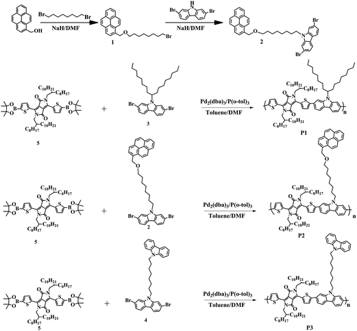
The synthetic routes for the pyrene group functionalized monomer (compound 2) and polymers are depicted in Scheme 1. Nucleophilic substitution of 1-pyrenemethanol and 1,8-dibromooctane yielded compound 1, which was reacted with 2,7-dibromocarbazole to afford compound 2. Compound 3, compound 4 and compound 5 were synthesized following the published references.25–27 Suzuki coupling polymerizations of the DPP monomer (compound 5) with compound 3, compound 2 and compound 4 yielded polymers P1, P2 and P3, respectively. The polymers were purified by successive Soxhlet extraction using acetone, hexane and subsequent reprecipitation. The molecular weight of the polymers was determined by using gel permeation chromatography (GPC) using polystyrene as the standard and THF as the eluent. The polymers possessed moderate number average molecular weights of 16.5–18.1 kDa with a polydispersity index of 1.95–2.69 (Table 1). All the polymers have excellent solubility in common organic solvents such as chloroform, chlorobenzene and 1,2-dichlorobenzene.| Polymer | Mn [kg mol−1] | PDI | UV-vis absorption | Cyclic voltammetry | Optical bandgap (eV) | ||||
|---|---|---|---|---|---|---|---|---|---|
| In CHCl3 | In film | HOMO [eV] | LUMO [eV] | ||||||
| λmax [nm] | λonset [nm] | λmax [nm] | λonset [nm] | ||||||
| P1 | 18.1 | 1.95 | 643 | 779 | 685 | 835 | −5.32 | −3.83 | 1.49 |
| P2 | 16.5 | 2.69 | 643 | 875 | 708 | 891 | −5.41 | −4.02 | 1.39 |
| P3 | 17.9 | 2.21 | 696 | 870 | 709 | 906 | −5.46 | −4.09 | 1.37 |
3.2. Thermal properties of polymers
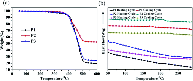
The polymers require excellent thermal properties in order to prevent efficiency degradation, which is important for the practical application of the OFET device. The thermal stabilities of the polymers were determined by thermogravimetric analysis (TGA) and differential scanning calorimetry (DSC) with a heating rate of 10 °C min−1 under a nitrogen atmosphere. As shown in Fig. 1(a), these polymers showed no mass loss in a wide range of temperatures with the 5% weight loss temperature of P1, P2 and P3 determined to be 373 °C, 366 °C and 369 °C, respectively.The thermodynamic behavior of the polymer was investigated by DSC and the thermograms are illustrated in Fig. 1(b). Polymer P1 exhibited a small endothermic peak at around 198 °C in the heating cycle, which should correspond to the phase transition from a solid to a liquid. The corresponding recrystallization peak can be observed at around 176 °C during the cooling cycle. For polymer P2, the melting temperature (Tm) and crystallization peak temperature (Tcc) moved to 232 °C and 205 °C, respectively. The higher Tm and Tcc of P2 than P1 should be due to the lower flexibility of the side chains due to the rigid fused ring attached to the terminal.28 The exothermal and endothermal peaks became even smaller for polymer P3, indicating that introducing the carbazole group to the terminal of the alkyl chain reduced the polymer crystallinity.29
3.3. XRD analyses
To further investigate the crystallinity and molecular stacking properties of the polymer, X-ray diffraction (XRD) analysis of the polymer film was performed and the results are illustrated in Fig. 2. The polymer film was spin coated from a chloroform solution on OTS-treated substrates and subsequently annealed in nitrogen. For polymers P1 and P2, the presence of sharp diffraction peaks (100) at around 2θ = 4.11° and 2θ = 4.06° indicated an intermolecular stacking ordering with interchain d-spacing distances of 2.17 nm and 2.15 nm, respectively. The similar XRD patterns of polymers P1 and P2 implied that introduction of the pyrene group to the alkyl chain terminal had no significant influence on the crystalline properties of the resulting polymer. The (100) diffraction of polymer P3 was located at a slightly shifted 2θ position (2θ = 4.33°) and the intensity of the (100) diffraction peak was decreased compared to polymers P2 and P3. The calculated interchain d-spacing distance of polymer P3 was 2.04 nm. These results are consistent with the analysis from the DSC measurement showing that polymer P3 is less crystalline than polymers P1 and P2. Due to the low crystallinity of the polymer, no distinctive diffraction peak corresponding to the π–π stacking was observed for polymers P1 and P3. Only polymer P2 showed a small diffraction peak at 2θ = 24.3°, implying an improved π–π* stacking.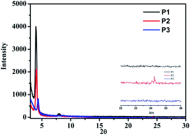 | ||
| Fig. 2 X-ray diffraction patterns of the annealed polymer thin films (annealing temperature: P1 = 150 °C, P2 = 180 °C, P3 = 180 °C). | ||
3.4. Optical and electrochemical properties of polymers
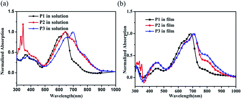
The normalized UV-vis absorption spectra of the polymers in chloroform and in film are shown in Fig. 3. Polymers P1 and P2 displayed two characteristic wavelength absorption bands in the range of 300–900 nm. The shorter wavelength absorbance at 300–500 nm originates from the π–π* transition of the polymer main chain, while the longer wavelength band from 500 nm to 900 nm can be attributed to the intramolecular charge transfer (ICT) from the electron-rich carbazole units to the electron-deficient DPP segments.30 Besides these two absorption bands, the polymer P2 exhibited a strong absorption in the range of 300–350 nm in solution, which can be ascribed to be the introduction of the pyrene group in the side chains.Compared to polymer P1 with an absorption maximum at 643 nm in solution, polymer P2 showed a similar absorption maximum but significant broadening of the ICT band. In addition, a ca. 50 nm bathochromic shift of the absorption maxima can be observed for polymer P3 in comparison with P1 in solution. Furthermore, polymer P1 exhibited a tailing of the absorption band with a shoulder peak at around 750 nm, which became more distinctive for polymers P2 and P3. Typically, a shoulder peak would appear on the right side of a main peak when the conjugated polymer forms aggregates.29 The enhanced shoulder peaks for polymers P2 and P3 may indicate that P2 and P3 tend to form more aggregates, which may originate from the facilitated π–π interactions between the conjugated backbones caused by the anchoring effect of the fused aromatic ring in the side chain terminal.31 Furthermore, the three polymers showed significantly different solution UV-vis absorption characteristics in spite of having the same polymer backbone, suggesting that polymer chains can preferentially form a certain degree of packing even in solution.32–34
An obvious solution-to-solid-state induced red-shift can be observed for polymer P1, due to the strengthened intermolecular interactions in film.35 For polymer P2, the shoulder peak at ca. 690 nm was significantly increased in film compared to that in solution. Although polymer P3 in film exhibited a similar absorption maximum to that in solution, the shoulder peak at ca. 800 nm became more distinct. By comparing the absorption spectra of the three polymers in film, not only a ca. 20 nm red-shift but also an enhanced shoulder peak can be observed for the polymers P2 and P3 compared to P1. These phenomena indicated that the introduction of a fused aromatic ring to the side chain terminal indeed gave rise to a significant influence on the aggregation properties. The optical band-gaps (Eoptg) deduced from the absorption edge of the thin film spectra are 1.49 eV, 1.39 eV, and 1.37 eV for polymers P1, P2 and P3, respectively.
To determine the highest occupied molecular orbital (HOMO) and lowest unoccupied molecular orbital (LUMO) levels of the polymers, cyclic voltammetry (CV) was performed on the polymer films by employing an ITO working electrode, a Pt counter electrode and an Ag/Ag+ reference electrode in 0.1 M tetrabutylammonium hexafluorophosphate in acetonitrile with a scan rate of 100 mV s−1. The results were calibrated using a ferrocene/ferrocenium redox couple and the HOMO level was calculated using the following equation:36  , where Eonsetox and
  are the onset of oxidation potential for the polymer and ferrocene against the Ag/AgCl reference electrode, respectively. The value −4.8 eV represents the HOMO level of ferrocene against a vacuum. Here, the
  was determined to be 0.4 eV.
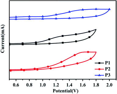
Fig. 4 displays the cyclic voltammograms and the detailed results are listed in Table 1. All the polymers showed stable and reversible p-doping processes in the oxidative scans. However, distinct n-doping peaks cannot be observed for the polymers so the n-doping process is not shown here and the LUMO level of the polymer was calculated from the difference between the HOMO level and the optical bandgap. The HOMO level was estimated to be −5.32 eV, −5.41 eV and −5.46 eV for P1, P2 and P3, respectively. The low-lying HOMO level can provide the polymers with superior air stability, which is favorable for the practical application of the OFET device. The LUMO energy levels of P1, P2 and P3 were approximately determined to be −3.83 eV, −4.02 eV and −4.09 eV, respectively. These results indicated that the introduction of a fused ring to the end of the side chains could also significantly affect the electronic properties of the polymers.
3.5. Characteristics of OFETs
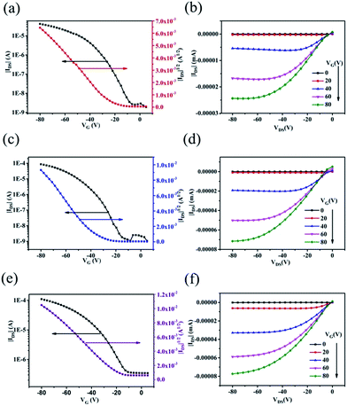
To evaluate the charge transport properties of the polymers, bottom-gate/top-contact OFET devices were fabricated through spin coating of the polymers on OTS-treated Si/SiO2 substrates. The obtained film thickness was ca. 45 nm. The active layers were annealed at various temperatures (ranging from 120 °C to 220 °C) on a hot plate under nitrogen for 10 min before the gold source and drain electrodes were thermally evaporated through shadow masks.The typical transfer (IDS–VGS) and output (IDS–VDS) characteristics of the OFET devices at different gate voltages (VGS) are illustrated in Fig. 5. The saturation field-effect mobility (μ) was calculated from the following equation:37 Ids = μ(W/2L)Ci(Vgs − Vth)2 where W and L are the channel width and length, respectively. Ci is the capacitance of the insulating SiO2 layer per unit area, Vgs and Vth are the gate voltage and the threshold voltage, respectively. The threshold voltage (Vth) was obtained as the x-axis intercept of the linear section of the plot of (Ids)1/2 vs. Vgs. The subthreshold swing was estimated by taking the inverse of the slope of Ids vs. Vgs in the region of exponential current increase. All the polymers exhibited typical p-channel characteristics in ambient air conditions. The detailed data including mobilities, on/off ratios, and threshold voltages are listed in Table 2. Thermal annealing has also been used to enhance the crystallinity and organization.4,5,12 The temperature was systematically optimized and the OFET devices were found to yield the maximum hole mobility after annealing at 150 °C, 180 °C and 180 °C for polymers P1, P2 and P3, respectively. Polymer P1 showed an optimum mobility of 0.019 cm2 V−1 s−1 with an on/off ratio of 104. Comparatively, by introducing the pyrene group in the side chain terminal, polymer P2 exhibited a higher mobility of 0.081 cm2 V−1 s−1 and a higher on/off ratio of 105. For polymer P3, possessing the carbazole at the end of the alkyl chain, a mobility of 0.052 cm2 V−1 s−1 was obtained. The enhanced mobility of polymers P2 and P3 probably can be ascribed to the stronger aggregation tendencies of P2 and P3, as evidenced by the UV-vis absorption.
| Polymer | Annealing temperature (°C) | Ion/off | VTH (V) | Hole mobility (cm2 V−1 s−1) |
|---|---|---|---|---|
| P1 | 120 | 103 | −15.3 | 0.016 |
| 150 | 104 | −23.1 | 0.019 | |
| 180 | 103 | −18.0 | 0.015 | |
| 210 | 103 | −15.2 | 0.013 | |
| P2 | 120 | 104 | −16.5 | 0.052 |
| 150 | 104 | −24.3 | 0.073 | |
| 180 | 105 | −30.9 | 0.081 | |
| 210 | 104 | −27.6 | 0.043 | |
| P3 | 120 | 105 | −14.1 | 0.046 |
| 150 | 104 | −21.2 | 0.049 | |
| 180 | 103 | −16.5 | 0.052 | |
| 210 | 103 | −21.6 | 0.020 |
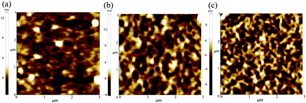
Tapping-mode atomic force microscopy (AFM) was employed to analyze the film morphology and provide valuable information on the film microstructure. As shown in Fig. 6, the film of polymer P1 showed relatively small domain size and root-mean-square roughness (RRMS) value of 1.194 nm. More ordered worm-like aggregates can be observed for the polymer P2 and P3 based films. The formed aggregates can act as charge transport junctions between conjugated backbones, effectively enlarging the charge carrier delocalization and facilitating interchain charge carrier transport.38 Moreover, the larger and well ordered aggregate formed by P2 is expected to provide a better connectivity for the charge transport. These interconnected aggregates can provide short-range order which can aid efficient intermolecular charge transfer as charges have a short scattering mean free path in the π-stacks.39 Charge transport in the aggregates can be described by a multiple trapping and release mechanism, which is less sensitive to π-stacking disorder.39,40 So although the introduction of the fused ring group in the terminal of the polymer side chain gave no increase in crystallinity, the induced aggregates can facilitate the interchain charge transport and consequently improve the charge mobility.41
4. Conclusion
In this paper, we have presented a strategy to improve the charge transport properties through side chain functionalization. Three polymers P1, P2 and P3 possessing the same carbazole–diketopyrrolopyrrole backbone but with different side chains have been designed and synthesized. For polymers P2 and P3, the terminal of the side chain was functionalized with a pyrene and carbazole group, respectively. The results indicated that the side chain modification not only influenced the optical and electrochemical properties of the polymer, but also led to an improved charge mobility. The enhanced aggregation tendency due to the introduction of the fused ring in the alkyl side chain terminal was supposed to be responsible for the improved charge carrier transport properties. This work has enabled us to better understand the relationships between the polymer side chains, optical and physical properties, aggregation behavior and charge mobility of the polymer. Additionally, our findings provide a different perspective to aid rational polymer design and the practical application of the OFET device.Acknowledgements
The authors would like to thank the National Natural Science Foundation of China (no. 21304018, 21374016), Jiangsu Provincial Natural Science Foundation of China (no. BK20130619, BK20130617).References
- Y. L. Guo, G. Yu and Y. Q. Liu, Adv. Mater., 2010, 22, 4427–4447 CrossRef CAS PubMed.
- C. Z. Liao, M. Zhang, M. Y. Yao, T. Hua, L. Li and F. Yan, Adv. Mater., 2015, 27, 7493–7527 CrossRef CAS PubMed.
- S. Mandal and Y. Y. Noh, Semicond. Sci. Technol., 2015, 30 Search PubMed.
- J. W. Ward, Z. A. Lamport and O. D. Jurchescu, ChemPhysChem, 2015, 16, 1118–1132 CrossRef CAS PubMed.
- H. Y. Wang, Y. Z. Xu, X. H. Yu, R. B. Xing, J. G. Liu and Y. C. Han, Polymers, 2013, 5, 1272–1324 CrossRef.
- Y. J. Cheng, S. H. Yang and C. S. Hsu, Chem. Rev., 2009, 109, 5868–5923 CrossRef CAS PubMed.
- Y. Sun, S.-C. Chien, H.-L. Yip, Y. Zhang, K.-S. Chen, D. F. Zeigler, F.-C. Chen, B. Lin and A. K. Y. Jen, J. Mater. Chem., 2011, 21, 13247–13255 RSC.
- M. J. Małachowski and J. Żmija, Opto–Electron. Rev., 2010, 18, 121–136 Search PubMed.
- Y. Li, P. Sonar, L. Murphy and W. Hong, Energy Environ. Sci., 2013, 6, 1684–1710 CAS.
- H. Guo, C. Weng, G. Wang, B. Zhao and S. Tan, Dyes Pigm., 2016, 133, 16–24 CrossRef CAS.
- S. Vegiraju, C.-M. Hsieh, D.-Y. Huang, Y.-C. Chen, P. Priyanka, J.-S. Ni, F. A. Esya, C. Kim, S. L. Yau, C.-P. Chen, C.-L. Liu and M.-C. Chen, Dyes Pigm., 2016, 133, 280–291 CrossRef CAS.
- C. Park, J. E. Park and H. C. Choi, Acc. Chem. Res., 2014, 47, 2353–2364 CrossRef CAS PubMed.
- B. Kang, W. H. Lee and K. Cho, ACS Appl. Mater. Interfaces, 2013, 5, 2302–2315 CAS.
- J. Mei and Z. Bao, Chem. Mater., 2014, 26, 604–615 CrossRef CAS.
- Y. Sun, C. Zhang, B. Dai, B. Lin, H. Yang, X. Zhang, L. Guo and Y. Liu, J. Polym. Sci., Part A: Polym. Chem., 2015, 53, 1915–1926 CrossRef CAS.
- Y. Sun, S.-C. Chien, H.-L. Yip, K.-S. Chen, Y. Zhang, J. A. Davies, F.-C. Chen, B. Lin and A. K. Y. Jen, J. Mater. Chem., 2012, 22, 5587–5595 RSC.
- C. Cabanetos, A. El Labban, J. A. Bartelt, J. D. Douglas, W. R. Mateker, J. M. J. Fréchet, M. D. McGehee and P. M. Beaujuge, J. Am. Chem. Soc., 2013, 135, 4656–4659 CrossRef CAS PubMed.
- J. Y. Back, H. Yu, I. Song, I. Kang, H. Ahn, T. J. Shin, S.-K. Kwon, J. H. Oh and Y.-H. Kim, Chem. Mater., 2015, 27, 1732–1739 CrossRef CAS.
- T. Lei, J.-Y. Wang and J. Pei, Chem. Mater., 2014, 26, 594–603 CrossRef CAS.
- B. Meng, H. Song, X. Chen, Z. Xie, J. Liu and L. Wang, Macromolecules, 2015, 48, 4357–4363 CrossRef CAS.
- K. Miao, G. J. Chae, X. Wu, Q. Shu, X. Zhu, B. Sun, J. Fan and S. Cho, RSC Adv., 2016, 6, 29164–29171 RSC.
- A. R. Han, J. Lee, H. R. Lee, J. Lee, S.-H. Kang, H. Ahn, T. J. Shin, J. H. Oh and C. Yang, Macromolecules, 2016, 49, 3739–3748 CrossRef CAS.
- C. Zeng, C. Xiao, R. Xin, W. Jiang, Y. Wang and Z. Wang, RSC Adv., 2016, 6, 55946–55952 RSC.
- Y. Zou, D. Gendron, R. Badrou-Aïch, A. Najari, Y. Tao and M. Leclerc, Macromolecules, 2009, 42, 2891–2894 CrossRef CAS.
- G. I. Nosova, D. A. Lypenko, R. Y. Smyslov, I. A. Berezin, E. V. Zhukova, E. I. Mal’tsev, A. V. Dmitriev, L. S. Litvinova, N. A. Solovskaya, O. V. Dobrokhotov, I. G. Abramov and A. V. Yakimanskii, Polym. Sci., Ser. B, 2014, 56, 59–76 CrossRef CAS.
- Y. Sun, B. Lin, H. Yang and X. Gong, Polymer, 2012, 53, 1535–1542 CrossRef CAS.
- J.-M. Park, S. K. Park, W. S. Yoon, J. H. Kim, D. W. Kim, T.-L. Choi and S. Y. Park, Macromolecules, 2016, 49, 2985–2992 CrossRef CAS.
- Y. Grohens, L. Hamon, G. Reiter, A. Soldera and Y. Holl, Eur. Phys. J. E: Soft Matter Biol. Phys., 2002, 8, 217–224 CrossRef CAS PubMed.
- S. Y. Son, Y. Kim, J. Lee, G.-Y. Lee, W.-T. Park, Y.-Y. Noh, C. E. Park and T. Park, J. Am. Chem. Soc., 2016, 138, 8096–8103 CrossRef CAS PubMed.
- Y. Sun, C. Zhang, Q. Huang, B. Dai, B. Lin, H. Yang, X. Zhang, L. Guo and Y. Liu, J. Mater. Chem. C, 2015, 3, 7669–7676 RSC.
- S. Qu, M. Li, L. Xie, X. Huang, J. Yang, N. Wang and S. Yang, ACS Nano, 2013, 7, 4070–4081 CrossRef CAS PubMed.
- Y. Zhang, J. Zou, H.-L. Yip, K.-S. Chen, J. A. Davies, Y. Sun and A. K. Y. Jen, Macromolecules, 2011, 44, 4752–4758 CrossRef CAS.
- T. Lei, J.-H. Dou, Z.-J. Ma, C.-H. Yao, C.-J. Liu, J.-Y. Wang and J. Pei, J. Am. Chem. Soc., 2012, 134, 20025–20028 CrossRef CAS PubMed.
- I. Kang, H.-J. Yun, D. S. Chung, S.-K. Kwon and Y.-H. Kim, J. Am. Chem. Soc., 2013, 135, 14896–14899 CrossRef CAS PubMed.
- P. Leclère, M. Surin, P. Viville, R. Lazzaroni, A. F. M. Kilbinger, O. Henze, W. J. Feast, M. Cavallini, F. Biscarini, A. P. H. J. Schenning and E. W. Meijer, Chem. Mater., 2004, 16, 4452–4466 CrossRef.
- J. L. Bredas, R. Silbey, D. S. Boudreaux and R. R. Chance, J. Am. Chem. Soc., 1983, 105, 6555–6559 CrossRef CAS.
- G. Horowitz, Adv. Mater., 1998, 10, 365–377 CrossRef CAS.
- Y. Liu, J. Zhao, Z. Li, C. Mu, W. Ma, H. Hu, K. Jiang, H. Lin, H. Ade and H. Yan, Nat. Commun., 2014, 5 Search PubMed.
- R. Noriega, J. Rivnay, K. Vandewal, F. P. V. Koch, N. Stingelin, P. Smith, M. F. Toney and A. Salleo, Nat. Mater., 2013, 12, 1038–1044 CrossRef CAS PubMed.
- A. T. Yiu, P. M. Beaujuge, O. P. Lee, C. H. Woo, M. F. Toney and J. M. J. Fréchet, J. Am. Chem. Soc., 2012, 134, 2180–2185 CrossRef CAS PubMed.
- Y. D. Park, H. S. Lee, Y. J. Choi, D. Kwak, J. H. Cho, S. Lee and K. Cho, Adv. Funct. Mater., 2009, 19, 1200–1206 CrossRef CAS.
Footnote |
| † Electronic supplementary information (ESI) available. See DOI: 10.1039/c6ra19914c |
| This journal is © The Royal Society of Chemistry 2016 |

