
Porous silicon–polyaniline hybrid composites synthesized through electroreduction of an aryldiazonium salt: preparation and photocurrent properties
Mariavitalia Tiddiaa,
Guido Mula a,
Michele Masciab,
Elisa Sechib and
Annalisa Vacca*b
a,
Michele Masciab,
Elisa Sechib and
Annalisa Vacca*b
aDipartimento di Fisica, Università degli Studi di Cagliari, Cittadella Universitaria di Monserrato, S.P. 8, Km 0.7, 09042 Monserrato, CA, Italy
bDipartimento di Ingegneria Meccanica, Chimica e dei Materiali, Università degli Studi di Cagliari, via Marengo 3, 09123 Cagliari, CA, Italy. E-mail: annalisa.vacca@dimcm.unica.it; Tel: +39 070 675 50 59
First published on 18th October 2016
Abstract
The results of an experimental study on the photocurrent properties of porous silicon (PSi) coated with polyaniline (PANI) are presented in this work. A three step approach is adopted for the fabrication of a stable and uniform coating: in the first step PSi electrodes were functionalized by electrochemical reduction of 4-nitrobenzenediazonium (NBD) salts in acetonitrile media, in the second step the nitro groups were electrochemically reduced to amino groups and in the last step aniline polymerization was performed on the surface of the aminophenyl-modified PSi. As a comparison, samples were prepared by direct polymerization of aniline onto PSi surfaces. The samples were characterized by reflectivity and photocurrent measurements. The results show an absorption capability of the NBD modified hybrid structures higher than those of the pristine PSi. The increase was in the range from 20% to 300%, depending on the wavelength. The photocurrent data are explained with the formation of a p–n junction between the polymer and semiconductor. The samples prepared by direct polymerization did not show appreciable variation with respect to the pristine PSi.
Introduction
In the last decade there have been many attempts to fabricate hybrid organic/inorganic structures to obtain materials with optimal electrical and optoelectronic properties for several kind of devices, such as light-emitting devices, solar cells, sensors and biosensors.1 To this aim, conducting polymers (CPs) have attracted significant interest and effort has been put in to understanding their conduction mechanisms and properties.2–4 A large varieties of CPs, with different structures and compositions are proposed, such as polyacetylene (PA), polyaniline (PANI), polythiophene (PT) and polypyrrole (PPy).5 CPs show good conductivities, although lower than metals, maintaining the mechanical properties of a polymer. Moreover, often CPs can switch their conductivity from p-type (electron-acceptor) to n-type (electron-donor) and vice versa.6In particular, PANI possesses outstanding properties such as a wide range of conductivity (from insulating to metallic regime), unique redox tunability, good environmental stability, low cost and ease of synthesis, as well as electrical conductivity significantly higher than a standard polymer.7 Researches have explored the applications of PANI in solar cells, capacitors and supercapacitors, ion and gas sensors.8–12
Among the methods to synthesize PANI, different electrochemical techniques such as cyclic voltammetry,13,14 potentiostatic,15,16 and galvanostatic17,18 have been successfully adopted. Depending on its redox state, PANI can be obtained in different forms: leucoemeraldine (LE), emeraldine (E), nigraniline (NA) and pernigraniline (PNA). The only conducting form of polyaniline is emeraldine salt, obtained by doping or protonation of emeraldine base with the imine nitrogens protonated by acids.19,20 The electrochemical growth and redox mechanisms of PANI has been widely investigated:21,22 the process starts with the formation of dimeric species from nucleophilic attack of the aniline on the nitrene cation radical, resulting in three dimerization products, as well as competitive degradation reactions.23
To realize hybrid nanocomposite materials a porous matrix can be coupled with this highly conductive organic conjugated polymer.24,25
Among the porous materials, PSi has been proposed for several applications, such as chemical and biological sensors, mainly because of its open pore structure, high specific area, biocompatibility, electroluminescence and photoluminescence properties.26–29 Photoconductive hybrid structures between PSi and conducting polymers have also been proposed.30–34
Hybrid structures of PANI and PSi have been investigated from 1993 by V. P. Parkhutik35 and studied as a rectifier exploiting the properties as a p–n junction using n and p-type PANI and p and n-type porous silicon.36,37 Different methods of coupling have been used such as spin coating and direct chemical or electrochemical polymerization of aniline onto the surface of PSi or oxidized PSi.38–40 A PSi/PANI immunosensor has been realized electrochemically with the aim to obtain stable immobilization of biomolecules and great sensitivity and specificity of the device.40
Two main limitations are often present in these systems: the high reactivity of hydrogen terminated silicon surface39 and the poor adhesion between PANI and substrates of different nature due to the lack of strong interfacial bonding.41 To overcome these limitations, Chiboub et al.39 proposed the chemical synthesis of aniline-terminated PSi surface by reacting brominated PSi layer with aniline molecules: the aniline moieties anchored onto the PSi surface were used as reactive sites for PANI polymerization. The functionalization of the surfaces by electroreduction of aryl diazonium has been proposed as a suitable way to realize an underlayer: the mechanism of reduction gives an aryl radical that covalently attaches to the surface of the material.42–44 Depending on the applications, two main approaches can be adopted for the functionalization which involve the diazotization in situ of aryl amines with NaNO2, followed by reductive grafting or the use of commercially available and stable diazonium salts, such as 4-nitrobenzenediazonium tetrafluoroborate.45 The latter approach allows avoiding the use of HCl and the problems arising from diffusion of NaNO2 inside such porous structures as PSi.
It has been demonstrated that the presence of an underlayer is able to improve the deposition of many polymers at metals and semiconductors surfaces.46–49
The electrodeposition of PANI using an underlayer obtained by electroreduction of aryl diazonium has been firstly employed by Santos et al.,50 who demonstrated that a thin layer of diphenylamine grafted on glassy carbon surfaces allows to improve the stability of the hybrid structures.
Recently, Jlassi et al.,51,52 performed the aniline polymerization in presence of the 4-diphenylamine diazonium-modified bentonite, obtaining exfoliated clay/polyaniline nanocomposites with improved dielectric and mechanical properties. A similar approach has been adopted by A. Mekki et al.,53 to synthesize multi-walled carbon nanotubes–polyaniline nanocomposites with enhanced conductive properties and high surface area.
In the present paper a layer-by-layer approach is proposed, in which a layer of phenyl amine has been electrochemically deposited on the surface of PSi and used as underlayer for the subsequent step of aniline electropolymerization. This multistep technique has been recently used to obtain stable and covalent bonds between: gold and poly(para-phenylene),54 PANI and gold,41 PANI and nanotubular TiO2![[thin space (1/6-em)]](https://www.rsc.org/images/entities/char_2009.gif) 25 and to the best of our knowledge has not been applied to hybrid PSi/PANI.
25 and to the best of our knowledge has not been applied to hybrid PSi/PANI.
The underlayer has been obtained through electrografting of 4-nitrobenzene from a corresponding diazonium salt followed by electrochemical reduction of the nitro group to amine. A similar approach has been used in our recent work:55 the grafting of the inner PSi surface with nitrophenyl moieties gave the samples a high resistance to strong etching solutions, which is useful for optical lithography where alkaline solutions are an integral part of the process, indicating a stable and uniform coverage of the pore surface. Moreover, the samples maintained open pores, mandatory for further functionalization of the structures.
Experimental section
Chemicals
Anhydrous acetonitrile (ACN, 99.8%), 4-nitrobenzenediazonium tetrafluoroborate (4-NBD salt), tetrabutylammonium hexafluorophosphate (TBAPF6), aniline (>99.5%) and potassium nitrate (KNO3) were purchased from SigmaAldrich®. Hydrofluoric acid (HF, 50%) and perchloric acid (HClO4, > 70%) were supplied by Carlo Erba. Pure ethanol was obtained from VWR. Aniline was freshly distilled and stored in the dark. The aqueous solutions were prepared with double-distilled water (18 MΩ cm).Apparatus
All electrochemical experiments were performed at room temperature using an AUTOLAB PGSTAT302N (Metrohm, Switzerland) potentiostat/galvanostat, equipped with a frequency response analyzer controlled with the NOVA software. A conventional hand-made three-electrode cell (V = 5 ml) made by a cylindrical Teflon chamber (base diameter = 2.5 cm; height = 5 cm) containing the electrolytic solution was used. The working electrode was located at the bottom of the cell and the electrical contact consists in an aluminum disc. The exposed geometrical area of the electrodes was 0.5 cm2 (diameter = 0.7 cm). A platinum titanium grid placed in front of the anode at 1 cm distance constituted the counter electrode. A platinum tip was used as quasi-reference electrode. All the potentials presented in this work refer to Pt quasi-reference electrode.Fabrication of PSi and electrochemical polymerization of polyaniline
PSi samples were fabricated using highly phosphorous-doped Si wafers (Siltronix) with a HF:H2O:EtOH solution in a 15:15:70 proportion, respectively. The current density applied was of 50 mA cm−2.30
PANI has been deposited on PSi substrates by three electrochemical steps. In the first step PSi electrodes were functionalized by cyclic voltammetry in ACN and 0.1 M TBAPF6 solutions containing 2 mM of 4-NBD. Five consecutive cycles were performed in the potential range −0.4/−1.2 V at scan rate of 10 mV s−1, followed by a potentiostatic step at −1.1 V for 300 s. Finally, two CV were carried out in the same solution. In the second step, the nitro groups were electrochemically reduced to amino groups in a water/ethanol solution (90/10%) v/v containing KNO3 0.1 M, through two CV by varying the potential from the open circuit potential to −1.7 V and back to −0.5 V. Finally, the polymerization of aniline was electrochemically performed by cyclic voltammetry in ACN solution containing perchloric acid (0.1 M) and aniline (0.1 M). ACN was used to ensure an easy penetration of the solution inside pores, due to the surface tension of 26 mN m−1 (25 °C). The potential was varied from the open circuit potential to −0.8 V and back to −0.2 V. In order to obtain PANI in the emeraldine salt form, the last scan of the polymerization was ended at −0.2 V in the anodic direction. Samples obtained by electropolymerization on aminophenyl modified PSi are denoted as PANI/Ar/PSi. Different PANI/Ar/PSi samples were prepared using different scan rate of polymerization from 30 mV s−1 to 100 mV s−1. Some samples have been also prepared with different number of potential cycles (from 4 to 10 cycles), at fixed scan rate of 30 mV s−1.
For comparison, the electrochemical polymerization of aniline was carried out directly at PSi sample, without the deposition of aminophenyl underlayer: these samples are denoted as PANI/PSi.
To remove any physisorbed, unreacted material from electrode surface, the electrodes were rinsed carefully with acetonitrile between each preparation step. Finally, the electrodes were dried with nitrogen stream.
Optical reflectivity and photocurrent measurements
Optical reflectivity measurements were performed by using a PerkinElmer Lambda 950 UV/Vis/NIR Spectrophotometer equipped with a Universal Reflectance Accessory. Optical simulation of reflectivity data was performed through WVASE® software (J. A. Woollam Co. Inc.).The photocurrent measurements were performed with samples covered with a sputtered semitransparent gold contact using a white light source (tungsten halogen lamp) focused on the samples surface by means of a microscope objective to a circular area with a diameter of 0.4 cm. The spectral behavior has been investigated by using a series of long-pass filters with various cutoff wavelengths in the 305–830 nm range, using a normalization procedure as described in a previous work.31
Results and discussion
Fig. 1 shows the first and the fifth cycle of electrografting of the diazonium salt on a PSi electrode. As can been seen the first cycle of the cathodic scan displays an irreversible cathodic peak at −0.7 V related to the reduction of aryl diazonium cations to aryl radicals, indicating a fast and easy reduction reaction on PSi surface.56 As the number of cycles increases the reduction peak become less evident, being still visible in the fifth cycle. This is indicative of the blocking effect of the deposited layer, which hinders the further reduction even if not completely, due to the large available surface of PSi. In order to fully functionalize the accessible surface of PSi, potentiostatic reduction of NDB was performed at −1.1 V for 300 s. The voltammetric scan after the potentiostatic reduction in Fig. 1 shows the attenuation of the reduction peak indicating a high degree of coverage of PSi surface with nitrophenyl layer. | ||
| Fig. 1 Cyclic voltammetries of PSi electrode in 2 mM NBD + 0.1 M (TBAPF6) at 10 mV s−1. | ||
The cyclic voltammetries related to the second electrochemical step of nitro group reduction to amine are presented in Fig. 2: a wide reduction wave is present in the first potential scan, while in the reverse scan an anodic shoulder can be appreciated between −0.7 and −0.6 V. Well-shaped redox peaks are visible when the reduction is performed at 10 mV s−1 of scan rate (see inset of Fig. 2).
 | ||
| Fig. 2 Cyclic voltammograms of PSi sample modified with NBD in water/ethanol media containing 0.1 M KNO3, scan rate: 100 mV s−1. Inset: cyclic voltammograms of PSi sample modified with NBD in water/ethanol media containing 0.1 M KNO3, scan rate: 10 mV s−1. | ||
The common accepted mechanism for the reduction of nitrophenyl moieties in protic medium involves the formation of the redox reversible couple nitrous/hydroxylamine (NO/NHOH), followed by the irreversible amination of the hydroxylamine group.57,58 According to this mechanism, the wave visible in the first cathodic scan can be related both to the formation of hydroxylamine intermediate and its irreversible reduction to NH2 groups, while the anodic wave indicates the formation of the nitrous group from the hydroxylamine intermediate.
In the second cycle, the extent of the reduction peak is significantly diminished, while the anodic peak is still visible, indicating that the reduction of nitro to amino group is not complete: about 90% of the electro-responsive groups is estimated to be converted in NH2, considering the voltammetric charges involved in reduction and oxidation processes.
The aminophenyl modified samples were then submitted to the electropolymerization in ACN solution containing perchloric acid (0.1 M) and aniline (0.1 M). As a comparison, pristine PSi samples were modified by direct electrochemical polymerization. As can be seen in Fig. 3, the first scan of polymerization is characterized by an increase of the anodic current for both samples, attributable to the oxidation of the aniline monomer to anilinium radical cation, which starts the polymerization process,59,60 indicating that the aminophenyl layer has not blocking effect on aniline oxidation.
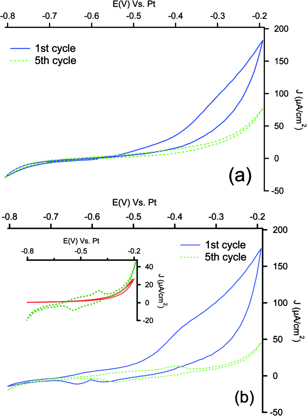 | ||
| Fig. 3 Cyclic voltammetry response recorded during electropolymerization of aniline in 0.1 M HClO4 + 0.1 M aniline in acetonitrile media on PSi (a) and Ar/PSi (b) at the scan rate of 30 mV s−1. Inset shows a magnification of 5th cycle, compared with the corresponding response of Ar/PSi in monomer-free solution (red curve). | ||
In the subsequent cycles, a couple of redox peaks is well visible only for PSi modified with aminophenyl layer (see magnification in inset of Fig. 3(b)). In order to check if these peaks could still be the response of residuals NO/NHOH groups of the reduced NBD layer in the acidic medium, cyclic voltammetries have been performed in a monomer-free solution before the electropolymerization. As can be seen, not appreciable signals can be detected in the polymerization range. The two peaks detected during the electropolymerization can be related to the redox transitions of PANI from leucoemeraldine to emeraldine and from emeraldine to pernigraniline.61 In the case of electropolymerization on pristine PSi samples, the redox couples are not visible neither in the fifth cycle, indicating that the polymerization process is more effective on aminophenyl modified electrode: similar behavior has been reported for gold and carbon based electrodes modified with PANI with and without aminophenyl layer.41,62 The polymerization of PANI is a self-catalytic head-to-tail process: the presence of aminophenyl layer grafted onto the PSi can promote the oxidative radicalic polymerization process and, due to the similarity of the organic layer to aniline, it can offer a large number of starting points for the aniline polymerization, allowing to obtain a more strongly adherent coating.63 The lower efficiency of polymerization observed with bare PSi may be due to concentration gradients between the porous layer and the bulk of the solution during the process. The concentration of aniline inside the pores (i.e. the concentration of reactant) is lowered by the formation of the anilinium radical cation. The monomer must then diffuse from the bulk to the porous layer, adding a mass-transfer resistance to the process. When the underlayer is present, the anilinium radicals may instead react with grafted phenylamine, which does not present diffusion limitations.
The presence of electroactive PANI layer on the PANI/Ar/PSi can be evidenced by cyclic voltammetries in monomer-free solutions. Fig. 4 shows the voltammograms recorded in ACN solution containing HClO4 0.1 M: the typical peaks related to doping and undoping of protons and anions in the polymeric film, as well as the transformation between different forms of PANI, are well visible at high values of scan rate.64
 | ||
| Fig. 4 Cyclic voltammetries performed on PANI/Ar/PSi electrodes in ACN monomer-free solutions containing HClO4 0.1 M at different scan rates. | ||
The optical reflectivity of PSi has been measured before and after electrochemical modification. Fig. 5 shows the comparison between pristine PSi and modified electrodes. The reflectivity spectra of pristine PSi show the two characteristic peaks of Si (for wavelengths shorter than about 450 nm) and a series of regular thin-film interference fringes due to the presence of the thin PSi layer on the bulk Si. The flatness of the external surface and of the PSi/Si interface gives rise to the interference figures where the PSi layer absorption coefficient is low (for wavelength longer than about 700 nm). In the region between 450 and 700 nm the contrast of the interference fringes is progressively reduced when going from longer to shorter wavelengths due to the increasing absorption coefficient of the porous layer until the light beam entering the PSi is entirely absorbed. The number and the position of the fringes depend on the optical thickness of the porous layer, that is the product of the refractive index times the real thickness. The refractive index of PSi depends on the porosity and, once that fixed, on the pores content. When filling the pores, the air is progressively replaced by the polymer, changing then the overall refractive index of the porous matrix. It is worth noting that since the pores size is more than one order of magnitude smaller that the shorter wavelength in this spectrum, all light scattering effects can be neglected.
 | ||
| Fig. 5 Reflectivity spectra: PSi and PANI/PSi (a); PSi and PANI/Ar/PSi (b). | ||
The comparison of spectra in Fig. 5(a) and (b) is interesting in view of understanding the different behaviours induced in the PANI and PSi composite with and without the presence of the aryl underlayer. Fig. 5(a) shows the PSi layer where PANI has been inserted without the aryl underlayer. It is evident that the PANI/PSi composite (green curve) does not show major differences with respect to the PSi reflectivity without PANI (black curve). This is not the same when the aryl layer is inserted before PANI, as shown in Fig. 5(b): PANI/Ar/PSi (green curve) shows a reflectivity spectrum where the thin layer interference fringes are significantly modified with respect to the pristine PSi layer (black curve). The presence of PANI also induces a significant reduction of the Si double peak, since the silicon surface is progressively covered. The displacement of the fringes is indicative of a modification of the optical thickness of the layer. Since the absence of features of a double layer excludes the possibility of a thick PANI layer onto the external PSi surface, the modification of the periodicity of the fringes can only be attributed to the presence of PANI within the pores, demonstrating the effectiveness of the filling process.
Fig. 6 shows the spectra of crystalline silicon, crystalline silicon with PANI and crystalline silicon with Ar/PANI: no interference fringes can be observed, while changes in the reflectivity are present in the region of wavelengths shorter than 1100 nm, which can be attributed to the optical response of PANI.
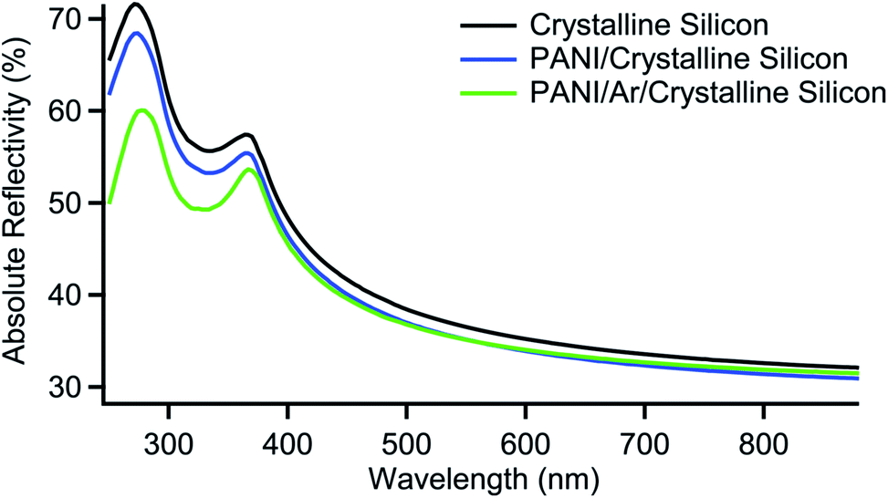 | ||
| Fig. 6 Reflectivity spectra of crystalline silicon, crystalline silicon with PANI and crystalline silicon with Ar/PANI. | ||
We analyzed the reflectivity data in Fig. 5 and 6, modeling the presence of PANI within the porous layer. The analyses show that PANI is present in the whole layer both with and without the aryl underlayer, while there is a gradient in the PANI concentration along the samples's thickness. The gradient is expected as is common in all thin pores filling processes. In our case, for PANI/Ar/PSi, the concentration gradient is such that the bottom concentration can be estimated to be about one third of the surface concentration. On a homogeneous layer fitting, i.e. without considering concentration gradients, the PANI filling can be evaluated as filling about 80% of the pores inner volume. This also can be expected since, given the dendritic structure of the PSi pores it is difficult for the aniline to fill every available volume portion. In summary, the reflectivity data fitting confirm the presence of the PANI in the whole structure and that a concentration gradient is also found. A comparison of the PANI/PSi results with the analysis of the reflectivity spectra of PANI/Ar/PSi shows a reduction of the PANI content when the under-layer is not present. Although a reliable quantitative evaluation of the PANI content is difficult with only the simulation of reflectivity spectra, a rough estimate suggests that the amount of PANI in PANI/PSi is less than two times the corresponding in PANI/Ar/PSi. These results confirm that at aminophenyl modified PSi the polymerization process is more effective.
To characterize the behavior of the samples, photocurrent measurements have been performed: the results are shown in Fig. 7.
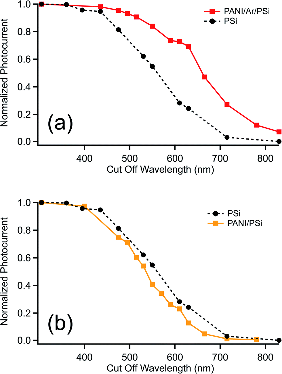 | ||
| Fig. 7 Comparison between normalized photocurrents of PSi and PANI/Ar/PSi (a), and PANI/PSi (b). | ||
The p–n junction between the organic layer and PSi improves the light absorption in the visible range compared to the empty porous silicon (Fig. 7(a)). The absolute white-light photocurrent was also higher for the hybrid junction. The PANI/Ar/PSi samples show a marked photosensitivity, higher with respect to pristine PSi by one order of magnitude. A different behavior can be observed with PANI/PSi (Fig. 7(b)): the photoresponse (yellow curve) is comparable to that of the pristine porous silicon; in the range between 400 and 800 nm the sample does not show the increase in absorbance obtained with PANI/Ar/PSi.
These results show the role of the underlayer in the functionalization of the hybrid structure. As a matter of fact, without underlayer it appears that the photocarrier generation contribution from the PANI content of the pore is negligible, while it is significant when the PANI impregnation is performed in a sample where the underlayer has been previously deposited. This may be due to the inefficiency of the interfacial junction between the organic and the inorganic components of the junction without aminophenyl layer, that possibly impedes the photocarriers generated within the polymer to cross the interface.
In order to study the effect of the different operative conditions, as the scan rate and the number of cycles of electropolymerization on the photocurrent, different PANI/Ar/PSi samples have been prepared using different scan rates of electropolymerization, maintaining the same conditions of preparation for the underlayer.
Fig. 8 shows the second polymerization cycle at different scan rate: as can be seen the current intensity of redox peaks of PANI polymerization are visible and they increase with the scan rate, indicating that PANI growth occurs under each examined condition.
 | ||
| Fig. 8 Cyclic voltammograms (2nd cycle) recorded during electropolymerization of aniline in 0.1 M HClO4 + 0.1 M aniline in acetonitrile media on PSi electrode after NBD reduction at the scan rate of 30, 50, 70 and 100 mV s−1. | ||
Fig. 9(a) and (b) shows photocurrents obtained for PANI/Ar/PSi samples with different scan rates and number of voltammetric cycles. As can be seen differences in the absolute value of the photocurrent are well visible: in particular, the photocurrent increases when the scan rate decreases and, when the scan rate is fixed the photocurrent increases with the number of cycles.
 | ||
| Fig. 9 Normalized photocurrent of PANI/Ar/PSi realized with 5 voltammetric cycles at different scan rates (a), or at 30 mV s−1 of scan rate and different number of cycles (b). | ||
It is well known that such characteristics as morphology, conductivity and rate of the polyaniline growth are strongly dependent on the operating conditions. When potentiodynamic electrodeposition is used, the scan rate can play an important role; the growth mechanism of PANI may occur via three different dimerization paths (i.e., head-to-head, head-to-tail, and tail to-tail), as well as competitive degradation reactions. Depending on the scan rate, the formation of polyaniline can be controlled by the fastest reaction (i.e., head-to-tail polymerization) or by the secondary reactions (e.g., tail-to-tail, head-to-head polymerizations, degradation reactions).23 In our case further issues complicate the process, since the polymerization occurs in a porous structure, where diffusion effects overlap the kinetics aspect. The number of CV cycles also affects the overall efficiency of the system, as shown in Fig. 9(b) for a series of samples prepared with a scan rate of 30 mV s−1, that increases the number of CV cycles.
Conclusions
A three step electrochemical procedure has been applied to prepare hybrid polyaniline/porous Si: the formation of an underlayer of phenyl amine promotes the polymerization of aniline. The results show that the covalent bond between the organic and the Si substrate is responsible for the formation of an effective heterojunction for light adsorption. PANI/Ar/PSi heterojunctions show an increased light absorption capability in the visible range, with respect to PSi, and generate higher photocurrents in the whole spectrum. Activity of samples obtained by simple electropolymerization of aniline on PSi, without underlayer, is virtually equal to those of pristine PSi.The photocurrent efficiency can be modified by setting the polymerization conditions, namely scan rate and number of voltammetric cycle. Under the conditions adopted in this work, coatings obtained at scan rates of 30 mV s−1 and with 10 voltammetric cycles of polymerization, show the highest capability to efficiently photogenerate carriers from light, mainly in the near-infrared region.
Acknowledgements
The authors acknowledge Prof. Maddalena Patrini from the University of Pavia (Italy) for useful discussions and reflectivity data analysis for evaluating the PANI content within the pores. The authors also acknowledge Regione Sardegna for financial support (L.R. 7/2007 – CRP – 59886 AMBROSIA Project and CRP – 78744 EnAPSi Project) and Istituto Nazionale Previdenza Sociale (INPS) for the PhD fellowships of Elisa Sechi.References
- S. Kango, S. Kalia, A. Celli, J. Njuguna, Y. Habibi and R. Kumar, Prog. Polym. Sci., 2013, 38, 1232–1261 CrossRef CAS.
- A. F. Diaz and J. A. Logan, J. Electroanal. Chem., 1980, 111, 111–114 CrossRef CAS.
- J. Rivnay, S. Inal, B. A. Collins, M. Sessolo, E. Stavrinidou, X. Strakosas, C. Tassone, D. M. Delongchamp and G. G. Malliaras, Nat. Commun., 2016, 7, 11287 CrossRef CAS PubMed.
- J. L. Bredas and G. B. Street, Acc. Chem. Res., 1985, 18, 309–315 CrossRef CAS.
- A. G. MacDiarmid, Angew. Chem., Int. Ed. Engl., 2001, 40, 2581–2590 CrossRef CAS.
- B. Wessling, D. Srinivasan, G. Rangarajan, T. Mietzner and W. Lennartz, Eur. Phys. J. E, 2000, 2, 207–210 CrossRef CAS.
- A. G. MacDiarmid, J. C. Chiang, M. Halpern, W. S. Huang, S. L. Mu, N. L. D. Somasiri, W. Wu and S. I. Yaniger, Mol. Cryst. Liq. Cryst., 1985, 121, 173–180 CrossRef CAS.
- W. Hou, Y. Xiao, G. Han, D. Fu and R. Wu, J. Power Sources, 2016, 322, 155–162 CrossRef CAS.
- D.-W. Wang, F. Li, J. Zhao, W. Ren, Z.-G. Chen, J. Tan, Z.-S. Wu, I. Gentle, G. Q. Lu and H.-M. Cheng, ACS Nano, 2009, 3, 1745–1752 CrossRef CAS PubMed.
- H. Su, T. Wang, S. Zhang, J. Song, C. Mao, H. Niu, B. Jin, J. Wu and Y. Tian, Solid State Sci., 2012, 14, 677–681 CrossRef CAS.
- P. Cavallo, E. Frontera, D. F. Acevedo, R. Olejnik, P. Slobodian, P. Saha and C. A. Barbero, Synth. Met., 2016, 215, 127–133 CrossRef CAS.
- A. Vacca, M. Mascia, S. Rizzardini, S. Corgiolu, S. Palmas, M. Demelas, A. Bonfiglio and P. C. Ricci, RSC Adv., 2015, 5, 79600–79606 RSC.
- A. Guiseppi-Elie, S. R. Pradhan, A. M. Wilson, D. L. Allara, P. Zhang, R. W. Collins and Y.-T. Kim, Chem. Mater., 1993, 5, 1474–1480 CrossRef CAS.
- A. Eftekhari and R. Afshani, J. Polym. Sci., Part A: Polym. Chem., 2006, 44, 3304–3311 CrossRef CAS.
- V. Gupta and N. Miura, Electrochem. Commun., 2005, 7, 995–999 CrossRef CAS.
- V. Rajendran, A. Gopalan, T. Vasudevan, W.-C. Chen and T.-C. Wen, Mater. Chem. Phys., 2000, 65, 320–328 CrossRef CAS.
- A. A. Hermas, M. Nakayama and K. Ogura, Electrochim. Acta, 2005, 50, 3640–3647 CrossRef CAS.
- G. S. Popkirov, E. Barsoukov and R. N. Schindler, J. Electroanal. Chem., 1997, 425, 209–216 CrossRef CAS.
- P. Fedorko, M. Trznadel, A. Pron, D. Djurado, J. Planès and J. Travers, Synth. Met., 2010, 160, 1668–1671 CrossRef CAS.
- A. MacDiarmid, J. Chiang, A. Richter and A. Epstein, Synth. Met., 1987, 18, 285–290 CrossRef CAS.
- C. C. Hu and C. H. Chu, J. Electroanal. Chem., 2001, 503, 105–116 CrossRef CAS.
- K. Aoki and M. Kawase, J. Electroanal. Chem., 1994, 377, 125–129 CrossRef CAS.
- Y.-T. Kim, H. Yang and A. J. Bard, J. Electrochem. Soc., 1991, 138, L71–L74 CrossRef CAS.
- V. Guarino, S. Zuppolini, A. Borriello and L. Ambrosio, Polymers, 2016, 8, 185–211 CrossRef.
- S. Palmas, M. Mascia, A. Vacca, J. Llanos and E. Mena, RSC Adv., 2014, 4, 23957–23965 RSC.
- L. Pavesi, L. Dal Negro, C. Mazzoleni, G. Franzo and F. Priolo, Nature, 2000, 408, 440 CrossRef CAS PubMed.
- J. Y. Fan, X. L. Wu, H. X. Li, H. W. Liu, G. S. Huang, G. G. Siu and P. K. Chu, Appl. Phys. A, 2006, 82, 485–487 CrossRef CAS.
- S. de Leon Ben Tabou, A. Sa'ar, A. R. Oren, M. E. Spira and S. Yitzchaik, Appl. Phys. Lett., 2004, 84, 4361–4363 CrossRef.
- H. Lin, T. Gao, J. Fantini and M. J. Sailor, Langmuir, 2004, 20, 5104–5108 CrossRef CAS PubMed.
- G. Mula, L. Manca, S. Setzu and A. Pezzella, Nanoscale Res. Lett., 2012, 7, 1–21 CrossRef PubMed.
- A. Pinna, F. Simbula, D. Marongiu, A. Pezzella, M. d'Ischia and G. Mula, RSC Adv., 2015, 5, 56704–56710 RSC.
- B. Urbach, N. Korbakov, Y. Bar-David, S. Yitzchaik and A. Sa'ar, J. Phys. Chem. C, 2007, 111, 16586–16592 CAS.
- A. Nahor, O. Berger, Y. Bardavid, G. Toker, Y. Tamar, L. Reiss, M. Asscher, S. Yitzchaik and A. Sa'ar, Phys. Status Solidi C, 2011, 8, 1908–1912 CrossRef CAS.
- A. Nahor, I. Shalev, A. Sa'ar and S. Yitzchaik, Eur. J. Inorg. Chem., 2015, 2015, 1212–1217 CrossRef CAS.
- V. P. Parkhutik, J. M. Martinez-Duart, R. D. Calleja and E. M. Matveeva, J. Electrochem. Soc., 1993, 140, L94–L95 CrossRef CAS.
- S. E. El-Zohary, M. A. Shenashen, N. K. Allam, T. Okamoto and M. Haraguchi, J. Nanomater., 2013, 568175 Search PubMed.
- I. Morsi, Sh. Ebrahim and M. Soliman, Int. J. Photoenergy, 2012, 917020 Search PubMed.
- P. Kumar, S. Adhikari and P. Banerji, Synthetic Met., 2010, 160, 1507–1512 CrossRef CAS.
- N. Chiboub, R. Boukherroub, N. Gabouze, S. Moulay, N. Naar, S. Lamouri and S. Sam, Opt. Mater., 2010, 32, 748–752 CrossRef CAS.
- C. A. Betty, Biosen. Bioelectron., 2009, 25, 338–343 CrossRef CAS PubMed.
- A. Vacca, M. Mascia, S. Rizzardini, S. Palmas and L. Mais, Electrochim. Acta, 2014, 126, 81–89 CrossRef CAS.
- M. Delamar, R. Hitmi, J. Pinson and J. M. Saveant, J. Am. Chem. Soc., 1992, 114, 5883–5884 CrossRef CAS.
- J. Pinson and F. Podvorica, Chem. Soc. Rev., 2005, 34, 429–439 RSC.
- P. Allongue, M. Delamar, B. Desbat, O. Fagebaume, R. Hitmi, J. Pinson and J. M. Saveant, J. Am. Chem. Soc., 1997, 119, 201–207 CrossRef CAS.
- A. A. Mohamed, Z. Salmi, S. A. Dahoumane, A. Mekki, B. Carbonnier and M. M. Chehimi, Adv. Colloid Interface Sci., 2015, 225, 16–36 CrossRef CAS PubMed.
- S. Palacin, C. Bureau, J. Charlier, G. Deniau, B. Mouanda and P. Viel, ChemPhysChem, 2004, 5, 1468–1481 CrossRef CAS PubMed.
- V. Mévellec, S. Roussel, L. Tessier, J. Chancolon, M. Mayne-L'Hermite, G. Deniau, P. Viel and S. Palacin, Chem. Mater., 2007, 19, 6323–6330 CrossRef.
- S. S. C. Yu, E. S. Q. Tan, R. T. Jane and A. J. Downard, Langmuir, 2007, 23, 11074–11082 CrossRef CAS PubMed.
- S. Mahouche-Chergui, S. Gam-Derouich, C. Mangeney and M. M. Chehimi, Chem. Soc. Rev., 2011, 40, 4143–4166 RSC.
- L. M. Santos, J. Ghilane, C. Fave, P. C. Lacaze, H. Randriamahazaka, L. M. Abrantes and J. C. Lacroix, J. Phys. Chem. C, 2008, 112, 16103–16109 CAS.
- K. Jlassi, A. Mekki, M. Benna-Zayani, A. Singh, D. K. Aswale and M. M. Chehimi, RSC Adv., 2014, 4, 65213–65222 RSC.
- K. Jlassi, S. Chandran, M. A Poothanari, M. Benna-Zayani, S. Thomas and M. M. Chehimi, Langmuir, 2016, 32, 3514–3524 CrossRef CAS PubMed.
- A. Mekki, S. Samanta, A. Singh, Z. Salmi, R. Mahmoud, M. M. Chehimi and D. K. Aswal, J. Colloid Interface Sci., 2014, 418, 185–192 CrossRef CAS PubMed.
- S. Descroix, G. Hallais, C. Lagrost and J. Pinson, Electrochim. Acta, 2013, 106, 172–180 CrossRef CAS.
- M. Tiddia, G. Mula, E. Sechi, A. Vacca, E. Cara, N. De Leo, M. Fretto and L. Boarino, Nanoscale Res. Lett., 2016, 11, 436 CrossRef PubMed.
- C. H. de Villeneuve, J. Pinson, M. C. Bernard and P. Allongue, J. Phys. Chem. B, 1997, 101, 2415–2420 CrossRef CAS.
- B. Ortiz, C. Saby, G. Y. Champagne and D. Belanger, J. Electroanal. Chem., 1998, 455, 75–81 CrossRef CAS.
- W. Richard, D. Evrard and P. Gros, J. Electroanal. Chem., 2012, 685, 109–115 CrossRef CAS.
- N. Pekmez, K. Pekmez, M. Arca and A. Yildiz, J. Electroanal. Chem., 1993, 353, 237–246 CrossRef CAS.
- M. Trchová, I. Šeděnková, E. N. Konyushenko, J. Stejskal, P. Holler and G. Ćirić-Marjanović, J. Phys. Chem. B, 2006, 110, 9461–9468 CrossRef PubMed.
- E. T. Kang, K. G. Neoh and K. L. Tan, Prog. Polym. Sci., 1998, 23, 227–324 CrossRef.
- L. Pilan, M. Raicopol, A. Pruna and V. Branzoi, Surf. Interface Anal., 2012, 44, 1198–1202 CrossRef CAS.
- H. C. Budnikov, G. A. Evtugyn and A. V. Porfireva, Talanta, 2012, 102, 137–155 CrossRef CAS PubMed.
- A. M. Massari, K. J. Stevenson and J. T. Hupp, J. Electroanal. Chem., 2001, 500, 185–191 CrossRef CAS.
| This journal is © The Royal Society of Chemistry 2016 |