Fabrication of highly photoluminescent quantum dot-polymer composite micropatterned surface using thiol-ene chemistry†
Chung-Hyeon Kima,
Jin-Hyuk Banga,
Ki Bum Hong*b and
Myoung-Hwan Park*a
aDepartment of Chemistry, Sahmyook University, Hwarangro 815, Nowon-gu, Seoul, 01795, Republic of Korea. E-mail: mpark@syu.ac.kr; pmhdream@gmail.com
bNew Drug Development Center (NDDC), Daegu-Gyeongbuk Medical Innovation Foundation (DGMIF), 80 Cheombok-ro, Dong-gu, Daegu, 41061, Republic of Korea. E-mail: kbhong@dgmif.re.kr
First published on 3rd October 2016
Abstract
Micropatterning of quantum dot (QD)-polymer nanocomposites exhibiting optically and electrically programmable properties in a large area with an organized array has been of great importance in various applications using photonic and optoelectronic devices. Here, we report the fabrication of a micropatterned QD-polymer composite exhibiting superior photoluminescence (PL) properties employing thiol-ene reaction and imprinting lithography techniques. The presence of positive charge on the QDs enhances the dispersion interaction between the QDs, and the presence of positively charged QDs containing allylic groups enables the QDs to form strong chemical binding to the polymer matrix. This phenomenon was confirmed using three different QDs; a neutral QD (QD-TOH), positive QD (QD-TTMA), and positive QD containing allylic groups (QD-TDMA–Ene). The synergetic effect of charge repulsion and chemical binding observed in our system induces a high PL with robustness of micropatterns. Moreover, the PL intensity linearly depends on the QD content in the polymer matrix, indicating easy controllability of the system, which can be used as a light-emitting source.
Introduction
Patterning of quantum dot (QD)-polymer microcomposites, exhibiting unique optical and electrical properties, in a large area with an organized array is of great importance in various applications related to photonic and optoelectronic devices including light-emitting devices,1 photoconductors,2 biological sensors,3 and solar cells.4 Colloidal QDs with exceptional air- and light stabilities5 were prepared via a less-expensive route employing a simple wet chemical synthesis method for achieving precise control in the size and shape of monodisperse materials, enabling them to be used in wet coating and post-processing. The tunable bandgap of semiconductor QDs for light-emitting sources that is governed by the quantum size effect induces tunable and pure colours exhibiting spectral purity and photoluminescence (PL) quantum yields. The programmability of optical and electrical properties of QDs has promoted their use in high-color-quality lighting and display applications, which can be evidenced by the large number of researches and patents reported recently by major corporations such as Samsung, Philips, LG Innotek, and Avago.6 However, the toxicity of heavy metals such as cadmium still offers challenges in using these materials for biological applications.7Most of the related earlier researches focused on the preparation of thin film QD superlattices, with the film properties strongly depending on the interparticle interactions which in turn depend on the particle size and the passivating ligand.8 In the case of small QDs with long ligands, ligand–ligand interaction dominates in their assembly, whereas the aggregation of QDs is governed by the dispersion interaction between the metal cores of a large particle containing short ligands. Recently, various strategies involving self-assembly of block copolymers,9 Langmuir–Schäfer,10 layer-by-layer (LbL) assembly,11 and imprinting lithography12 have been developed to produce/pattern QD incorporated polymer composites exhibiting controlled morphology and thickness in order to minimize the use of QDs, which are expensive, and retain their strong PL quantum yields. The formation of QD-polymer composites in a large area while preserving the high PL quantum yields and photostability would depend on how well the QDs are dispersed and stabilized in the polymer matrix.13 Since most of the strategies based on weak secondary interaction or complex/multiple processes limit the use of QDs, many researchers have recently focused on efficiently stabilizing QDs in a matrix and retaining their high PL properties.
Here, we develop a simple process for micropatterning QD-polymer composites on a desired area employing several conspicuous processes (Scheme 1). Initially, the repulsion between the charged QDs is assumed to prevent their close aggregation which decreases the PL quantum yields during a spin/drop coating process. Secondly, the QD-polymer composite is patterned onto a thiol-functionalized glass substrate employing imprinting lithography. Finally, the polymerization of the allyl groups on the QDs and the thiol groups of the monomers is carried out through thiol-ene reaction with silanation. These three steps enable the stable dispersion of QDs in the polymer matrix while retaining their strong PL.
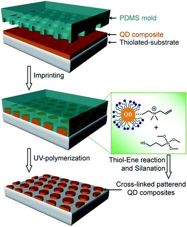 | ||
| Scheme 1 Schematic illustration of the fabrication of micropatterned QD-polymer composites employing thiol-ene cross-linking and imprinting lithography. | ||
Experimental
Material and instruments
11-Bromo-1-undecanol (98%), triphenylmethanethiol (97%), methanesulfonyl chloride (MsCl, 98%), trifluoroacetic acid (TFA, ≥ 99%, liquid), triisopropylsilane (TIPS, 98%), trimethylamine (TMA, ≥99.5%), triethylamine (TEA, ≥99%), N,N-dimethylallylamine, cadmium oxide (CdO, ≥99.99%), selenium (powder, 99.99%), tetradecylphosphonic acid (TDPA, 97%), and (3-(methacryloyloxy)propyl)trimethoxysilane (MPS, 98%) were purchased from Korea-Sigma-Aldrich. Bis(trimethylsilyl) sulfide ((TMS)2S, 95.0%), diethylzinc (ZnEt2, 17% in hexane), tri-n-octylphosphine (TOP, >85.0%), tri-n-octylphosphine oxide (TOPO, >95.0%), hexadecylamine (HDA, >95.0%) were purchased from Tokyo Chemical Industry Co., Ltd. (TCI, Japan). All reagents were stored under inert atmosphere and used without employing any further purification process. The Sylgard 184 silicone elastomer kit was purchased from Fisher Scientific. 1H nuclear magnetic resonance (NMR) was employed to characterize the chemical structures of the synthesized molecules using an NMR ECX-400 instrument (JEOL, Japan), and the prepared composites were cured in a 40 W UVA UV curing chamber (Minuta, Korea). Transmission electron microscopy (TEM) and scanning electron microscopy (SEM) images were acquired on JEOL 1000CX (JEOL, Japan) operating at 80 keV and JSM-6510 (JEOL, Japan) instruments, respectively. The absorption and PL spectra were collected using a Neosys-2000 UV-Vis spectrophotometer (Scinco, USA) and a QM-400 spectrofluorometer (PTI, USA), respectively. Fluorescence images were obtained with BX 53 fluorescence microscopy (Olympus, Japan) and confocal microscopy using a Leica TCS SP8 instrument (Leica, Germany).Fabrication of TOPO-QDs
QD fabrication: CdO (12 mg, 0.08 mmol), TDPA (44.7 g, 0.16 mmol), and TOPO (800 mg, 2.07 mmol) were combined in a 25 mL three-neck flask and heated to 300 °C under argon atmosphere. After 1 h, the solution turned optically clear, and Se solution (Se, 10 mg, 0.11 mmol) in 480 μL TOP was rapidly injected to the hot solution followed by stirring at 280 °C for 1.5 h. The solution was allowed to cool to room temperature. The obtained CdSe QDs were purified with methanol and recovered via centrifugation. Subsequently, the CdSe core solution (<4 mL) was mixed with TOPO (800 mg, 2.07 mmol) and hexadecylamine (HAD, 300 mg, 1.24 mmol) followed by heating to 150 °C for 1 h. ZnEt2 (0.8 mL, 0.8 mmol) in 480 uL TOP and (TMS)2S (56 μL, 0.26 mmol) in 2 mL TOP were used as a shell solution. After injecting the shell solution, the QD mixture was allowed to react with it for 1 h at 100 °C. The obtained CdSe/ZnS QDs were purified and precipitated with CHCl3 and methanol and stored in toluene.Two-step ligand exchange reaction of QDs
QD-TTMA and QD-TDMA–Ene were prepared using a two-step ligand exchange process.14 Initially, the TOPO-coated CdSe QD (10 mg) solution was dried and TEG-OH ligands (100 mg) in absolute methanol (10 mL) were added. The reaction mixture was stirred at room temperature for 24 h under inert atmosphere for completely solubilizing the QDs in methanol. The QDs were then purified with hexane, and cationic thiol ligands (30 mg) were added to QD-TOH in methanol with stirring for 24 h at room temperature. As a result, the cationic thiol ligands slowly substituted the TOH ligands on the QD surface owing to the presence of predominant amount of cationic ligands as compared with the small amount of TOH ligands. After stirring for 24 h, methanol was evaporated, and the QDs were re-dispersed in water followed by purifying the aqueous QD sample by dialysis. The QD-TTMA and QD-TDMA–Ene samples were analyzed employing UV-Vis, spectrofluorimeter, and TEM measurements.Fabrication of QD-polymer composites
A polydimethylsiloxane (PDMS) mold was fabricated by pouring a 10![[thin space (1/6-em)]](https://www.rsc.org/images/entities/char_2009.gif) :
:![[thin space (1/6-em)]](https://www.rsc.org/images/entities/char_2009.gif) 1 (v/v) mixture of Sylgard 184 elastomer and a curing reagent using a silica master with hole or line micropatterns. The mixture was placed for 12 h at room temperature, cured for 1 h at 60 °C, and was then peeled off from the master. A homogeneous mixture of QDs and MPS (0.5 mL) in DMSO (0.5 mL) was drop-casted on a thiol-functionalized glass substrate, and the PDMS mold was subsequently placed on the substrate under high pressure. After performing UV irradiation for 1 h, the mold was removed and the substrate was vigorously washed several times with methanol.
1 (v/v) mixture of Sylgard 184 elastomer and a curing reagent using a silica master with hole or line micropatterns. The mixture was placed for 12 h at room temperature, cured for 1 h at 60 °C, and was then peeled off from the master. A homogeneous mixture of QDs and MPS (0.5 mL) in DMSO (0.5 mL) was drop-casted on a thiol-functionalized glass substrate, and the PDMS mold was subsequently placed on the substrate under high pressure. After performing UV irradiation for 1 h, the mold was removed and the substrate was vigorously washed several times with methanol.
Results and discussion
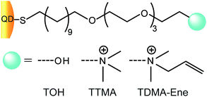
The important aim in the formation of QD-polymer composites is the proper dispersion and stabilization of the QDs in a polymer matrix. We presumed that the presence of positively charged QDs containing allylic groups (QD-TDMA–Ene) would enhance the dispersion and stability of QDs in the matrix. The repulsion between the charged ligands on QDs might result in decreasing their aggregation and enhancing their dispersion interaction in the composite solution. In addition, when the well-dispersed QDs are present in the polymerization medium where the polymer precursors are cross-linked together through thiol-ene reaction, the well-dispersed QDs would be strongly held in the composite. This was confirmed by fabricating QDs with three different ligands (Scheme 2): a neutral ligand (TOH), positively charged ligand (TTMA), and positively charged ligand containing allylic groups (TDMA–Ene).ZnS-passivated CdSe core–shell QDs were prepared according to a known procedure using a CdO-based method.15 Initially, TOPO-coated CdSe core was synthesized from CdO and elemental Se using a kinetic growth method where the particle size depends on the reaction time. Subsequently, the core was capped with ZnS using TOP at high temperature.16 Initially, the dried TOPO-coated CdSe/ZnS particles were functionalized with TOH ligand solution in methanol for solubilizing the QDs in methanol. Ligand-exchange of the QD-TOH was then performed with TTMA or TDMA–Ene ligands to form QD-TTMA and QD-TTMA–Ene, respectively. QD-TOH is soluble in methanol but insoluble in water, whereas QD-TTMA and QD-TDMA–Ene are soluble in both methanol and water. The zeta potential (δ) values obtained for QD-TTMA (δ = 38.1 mV) and QD-TDMA–Ene (δ = 40.2 mV) in phosphate-buffered saline (PBS) solution of pH 7.4 indicate the success of the method of introducing cationic ligands to form cationic QDs by ligand exchange.13
In addition, the successful synthesis of the QDs was verified using UV-Vis, spectrofluorimeter, and TEM analyses. Absorption and PL spectra of QD-TOPO, QD-TOH, QD-TTMA, and QD-TDMA–Ene are shown in the Fig. 1a. The maximum wavelength (λmax) of absorption and PL peaks for QD-TOPO is located at 543 and 565 nm, respectively, and the peaks remain unchanged after performing the ligand-exchange reactions with TOH, TTMA, and TDMA–Ene. The diameters of QDs are calculated to be in the range of 4.0–4.2 nm by examining the size-dependent PL color.17 The size of the monodisperse QDs is further confirmed with the help of TEM images shown in the Fig. 1b–e.
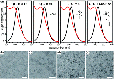 | ||
| Fig. 1 (a) UV-Vis (red line) and PL (black line) spectra of the QDs. TEM images of (b) QD-TOPO, (c) QD-TOH, (d) QD-TTMA, and (e) QD-TDMA–Ene. All scale bars are 30 nm. | ||
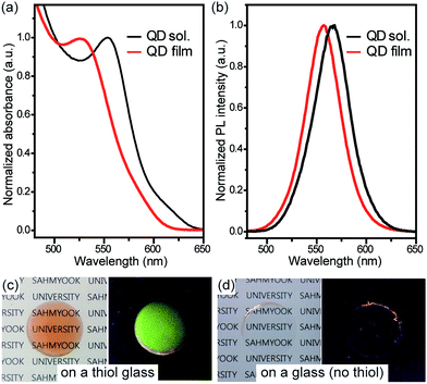
To demonstrate the enhanced transparency and PL properties, a solution containing QD-TDMA–Ene and MPS was coated on thiol-functionalized and control (no thiol) glass substrates containing no patterns followed by performing polymerization by UV irradiation with a wavelength of 365 nm. The homogeneously dispersed QD film exhibits a blue shift in the λmax of the absorption and PL peaks, and the QD solution retains its narrow-shaped peak after polymerization (Fig. 2a and b). This result indicates that the blue shift is associated to the changes in environment surrounding the QDs, and not the aggregation occurring after the film formation.18 Fig. 2c and d show the photographs of the QD-polymer films on thiol-functionalized and control glass (no thiol) substrates under 365 nm UV light and ambient light. The QD-polymer film efficiently immobilized on the thiol-functionalized glass substrate exhibits a strong fluorescence and clear transparency with a good adhesion whereas a few residues are present and fluorescence in a corner is observed for the film on the control glass substrate. These results indicate that stable QD films are formed on the thiol-functionalized glass substrate through chemical bonding.
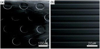
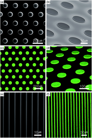
Micropatterns of QD-polymer composites were fabricated using the PDMS mold fabricated from the silica master with hole or line micropatterns (Fig. 3) through thiol-ene reaction and silanation as shown in the Scheme 1. The substrates with the hole and line micropatterns were characterized using SEM and confocal microscopy. Fig. 4a and b show the SEM images of vertical and tilted QD-polymer composite samples exhibiting pillars with a diameter of 100 μm and a thickness of 2.0 μm formed after imprinting. In addition, highly florescent images are obtained for the imprinted pillars of the QD-polymer composites in the vertical and tilted modes (Fig. 4c and d). Similarly, the imprinted line micropatterns obtained using the same method are analysed with the SEM and confocal images shown in the Fig. 4e and f.
To demonstrate the effectiveness of the functional groups on QDs in enhancing their PL in the polymer matrix, three different functional groups were examined by preparing a neutral QD (QD-TOH), positive QD (QD-TTMA), and positive QD containing allylic groups (QD-TDMA–Ene) (Scheme 2). The image with the weakest fluorescence for the pillar is obtained for the neutral QD-TOH owing to the weak dispersion interaction (Fig. 5c) whereas an enhanced fluorescent image is obtained with the positive QD-TTMA indicating a good dispersion interaction owing to repulsion due to the presence of positive charge on the QDs (Fig. 5b). A highly enhanced PL intensity is observed with QD-TDMA–Ene since the QDs are stabilized in the polymer matrix with the additional thiol-ene reaction occurring during UV polymerization (Fig. 5a). The synergetic effect of the enhanced dispersion interaction and thiol-ene cross-linking obtained with QD-TDMA–Ene induces a strong PL quantum yield that can be efficiently applied in photonic and optoelectronic systems.
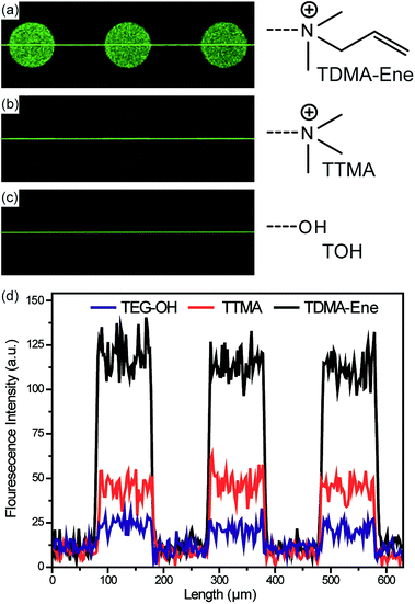 | ||
| Fig. 5 Confocal PL images with (a) QD-TDMA–Ene, (b) TTMA, and (c) TOH. (d) The corresponding PL profile. | ||
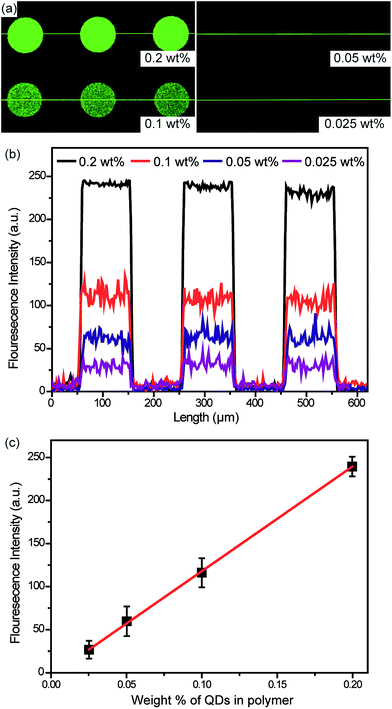
To further fabricate a system that can be efficiently programed to be used as a light-emitting source, the QD content in the polymer matrix was controlled by adding 0.025, 0.05, 0.01, and 0.2 wt% of QDs in MPS, and the PL micropatterns were characterized using confocal microscopy. As the amount of QDs in the composites increases, the PL intensity increases (Fig. 6). In addition, a linear relationship between the amounts of QDs and polymers is observed with our QD-composite micropatterns, whose brightness can be readily programmed in light-emitting devices.
Conclusions
We have fabricated QD-polymer micropatterned surfaces exhibiting high PL quantum yields employing thiol-ene reaction and imprinting technique. The positive charge present on the QDs resulted in enhancing the dispersion interaction between QDs, and the positively charged QDs containing allylic groups enabled the QDs to form strong chemical binding to the polymer matrix. This phenomenon was confirmed using three different types of QDs; a neutral QD (QD-TOH), positive QD (QD-TTMA), and positive QD containing allylic groups (QD-TDMA–Ene). This synergetic effect of the charge repulsion and the chemical binding in our system gave rise to high PL of micropatterns with robustness. Due to the difficulty in fabricating a nanopatterned PDMS mold, all of our achievements were performed at micron scale, but the system can be extended to fabricate nanopatterned QD composite surface using a special mold with nanopatterns. Additionally, the PL intensity linearly depends on the content of QDs in the polymer matrix, indicating that the system can be easily programmed to serve as a light-emitting source. These QD-polymer composites, which are well dispersed and stabilized in a polymer matrix, might exhibit the potential in enhancing the PL quantum yields to be used in various systems including photonic and optoelectronic devices.Acknowledgements
This work was supported by Basic Science Research Program through the National Research Foundation of Korea (NRF) funded by the Ministry of Science, ICT & Future Planning (NRF-2013R1A1A1076019).References
- Y. Shirasaki, G. J. Supran, M. G. Bawendi and V. Bulović, Nat. Photonics, 2013, 7, 13–23 CrossRef CAS; P. O. Anikeeva, J. E. Halpert, M. G. Bawendi and V. Bulovic, Nano Lett., 2009, 9, 2532–2536 CrossRef PubMed; Q. Sun, Y. A. Wang, L. S. Li, D. Wang, T. Zhu, J. Xu, C. Yang and Y. Li, Nat. Photonics, 2007, 1, 717–722 CrossRef.
- Q. Li and R. M. Penner, Nano Lett., 2005, 5, 1720–1725 CrossRef CAS PubMed; M. Chen, H. Yu, S. V. Kershaw, H. Xu, S. Gupta, F. Hetsch, A. L. Rogach and N. Zhao, Adv. Funct. Mater., 2014, 24, 53–59 CrossRef; S. J. Kim, W. J. Kim, Y. Sahoo, A. N. Cartwright and P. N. Prasad, Appl. Phys. Lett., 2008, 92, 031107 CrossRef.
- W. J. Parak, T. Pellegrino and C. Plank, Nanotechnology, 2005, 16, R9 CrossRef CAS PubMed; I. L. Medintz, H. T. Uyeda, E. R. Goldman and H. Mattoussi, Nat. Mater., 2005, 4, 435–446 CrossRef PubMed; T. Jamieson, R. Bakhshi, D. Petrova, R. Pocock, M. Imani and A. M. Seifalian, Biomaterials, 2007, 28, 4717–4732 CrossRef PubMed.
- I. Robel, V. Subramanian, M. Kuno and P. V. Kamat, J. Am. Chem. Soc., 2006, 128, 2385–2393 CrossRef CAS PubMed; P. V. Kamat, J. Phys. Chem. C, 2008, 112, 18737–18753 Search PubMed; R. Plass, S. Pelet, J. Krueger, M. Grätzel and U. Bach, J. Phys. Chem. B, 2002, 106, 7578–7580 CrossRef.
- J. Tang, L. Brzozowski, D. A. R. Barkhouse, X. Wang, R. Debnath, R. Wolowiec, E. Palmiano, L. Levina, A. G. Pattantyus-Abraham and D. Jamakosmanovic, ACS Nano, 2010, 4, 869–878 CrossRef CAS PubMed.
- J. Oliver, NANO27C, BCC Research, 2011 CrossRef CAS PubMed; R. A. McIntyre, Sci. Prog., 2012, 95, 1–22 CrossRef CAS PubMed.
- S. J. Rosenthal, J. C. Chang, O. Kovtun, J. R. McBride and I. D. Tomlinson, Chem. Biol., 2011, 18, 10–24 CrossRef CAS PubMed; R. Hardman, Environ. Health Perspect., 2006, 114, 165–172 CrossRef PubMed; M.-H. Park, J. Toxicol. Environ. Health Sci., 2015, 7, 277–281 CrossRef; J. Park, G.-S. Jin, M. S. Hwang, M. T. Brown and T. Han, J. Toxicol. Environ. Health Sci., 2016, 8, 86–95 CrossRef.
- G. Markovich, C. P. Collier, S. E. Henrichs, F. Remacle, R. D. Levine and J. R. Heath, Acc. Chem. Res., 1999, 32, 415–423 CrossRef CAS.
- J. Y. Cheng, A. M. Mayes and C. A. Ross, Nat. Mater., 2004, 3, 823–828 CrossRef CAS PubMed.
- G. M. Lowman, S. L. Nelson, S. M. Graves, G. F. Strouse and S. K. Buratto, Langmuir, 2004, 20, 2057–2059 CrossRef CAS PubMed.
- Y. W. Lin, W. L. Tseng and H. T. Chang, Adv. Mater., 2006, 18, 1381–1386 CrossRef CAS.
- M. J. Hampton, J. L. Templeton and J. M. DeSimone, Langmuir, 2010, 26, 3012–3015 CrossRef CAS PubMed.
- A. Biswas, A. Saha, D. Ghosh, B. Jana and S. Ghosh, Soft Matter, 2014, 10, 2341–2345 RSC; S. Ghosh, C. Hentrich and T. Surrey, ACS Chem. Biol., 2013, 8, 673–678 CrossRef CAS PubMed; M. Bhagawati, S. Ghosh, A. Reichel, K. Froehner, T. Surrey and J. Piehler, Angew. Chem., Int. Ed., 2009, 48, 9188–9191 CrossRef PubMed; A. Biswas, A. Saha, B. Jana, P. Kurkute, G. Mondal and S. Ghosh, ChemBioChem, 2013, 14, 689–694 CrossRef PubMed.
- Y.-C. Yeh, D. Patra, B. Yan, K. Saha, O. R. Miranda, C. K. Kim and V. M. Rotello, Chem. Commun., 2011, 47, 3069–3071 RSC.
- L. Qu and X. Peng, J. Am. Chem. Soc., 2002, 124, 2049–2055 CrossRef CAS PubMed.
- S. Haubold, M. Haase, A. Kornowski and H. Weller, ChemPhysChem, 2001, 2, 331–334 CrossRef CAS PubMed.
- V. Biju, T. Itoh, A. Anas, A. Sujith and M. Ishikawa, Anal. Bioanal. Chem., 2008, 391, 2469–2495 CrossRef CAS PubMed.
- B. Venugopal, N. Ravishankar, C. R. Perrey, C. Shivakumara and M. Rajamathi, J. Phys. Chem. B, 2006, 110, 772–776 CrossRef CAS PubMed.
Footnote |
| † Electronic supplementary information (ESI) available: Experimental procedures and scheme for synthesis of TOH, TTMA, and TTMA–Ene ligands and their 1H NMR spectra. See DOI: 10.1039/c6ra19581d |
| This journal is © The Royal Society of Chemistry 2016 |

