
 Open Access Article
 This Open Access Article is licensed under a Creative Commons Attribution-Non Commercial 3.0 Unported Licence
Ultra-fast microwave-assisted reverse microemulsion synthesis of Fe3O4@SiO2 core–shell nanoparticles as a highly recyclable silver nanoparticle catalytic platform in the reduction of 4-nitroaniline†
C. Y.
Lu
*ab,
T.
Puig
b,
X.
Obradors
b,
S.
Ricart
b and
J.
Ros
a
aDepartament de Quimica, Edifici C Facultat de Ciències, Universitat Autònoma de Barcelona (UAB), Cerdanyola del Vallès, Barcelona 08193, Spain. E-mail: lu.changyong@e-campus.uab.cat
bInstitute of Materials Science of Barcelona (ICMAB-CSIC), Campus de la UAB, Cerdanyola del Vallès, Barcelona 08193, Spain
First published on 12th September 2016
Abstract
A novel microwave-assissted reverse microemulsion method was applied to prepare Fe3O4@SiO2 core–shell nanoparticles rapidly for the first time. The morphology of the core–shell structure is controlled by tunning the reaction parameters. Nanoparticles with a very thin SiO2 coating layer (2.5 nm) containing a single Fe3O4 nanoparticle (8–9 nm) are produced. These core–shell nanoparticles can be used as solid catalytic supports for Ag nanoparticles and applied in 4-nitroaniline reduction. Transmission electron microscopy showed that the core–shell nanoparticles were decoracted with Ag nanoparticles of 7 nm in diameter. The crystal structures of the Fe3O4 and Ag nanoparticles were confirmed by X-ray diffraction. These Ag/Fe3O4@SiO2 nanocomposites showed high catalytic efficiency and recycling properties even after 20 times of repetation.
Introduction
Due to their unique magnetic properties and biocompatibility, iron oxide nanoparticles have been intensively studied for the past few decades for wide applications in biotechnology, data storage, magnetic fluids and catalysis.1,2 Nobel metal nanomaterials, like Au, Pt and Ag, are promising catalysts for many reactions, for example Au nanoclusters can be used in the selective oxidation of styrene3 and Pt-based heterogeneous nanomaterials are promising catalysts in direct methanol fuel cells.4 Ag nanoparticles have also been comprehensively studied for their promising application in biotechnology and catalysis. Compared with other noble metal nanoparticles, such as Au, Pt and Pd, Ag nanoparticles are cheaper and have some special properties like antibacterial activity, plasmon resonant optical properties and an enhancing the effect of radiation treatment, which make them ideal candidates for biomarkers, optical sensors and antimicrobial drugs.5,6 It is also worth noting that using Ag NPs as the catalyst to reduce nitroaniline would be an effective and environmentally friendly procedure to synthesize amino compounds.7Because of the multifunctional requirement, Fe3O4/Ag composite materials with the combination of excellent magnetic properties, biocompatibilities and plasmonic properties would be a promising composite for multiple applications. However the uncovered Fe3O4 NPs were easy to oxidized and aggregated during the preparation and application process. The chemical and thermal stable silica layers could be a nice candidate for decorating and protect the iron oxide nanoparticles' surface. And the nontoxic silica provides Fe3O4 nanoparticles with water solubility as well as good biocompatibility, which has potential applications in bio-imaging and drug delivery.8 For the research in functional materials, Fe3O4@SiO2@Y2O3:Eu3+ core–shell structures have magnetic response performance and luminescent properties9 and the Fe3O4@SiO2@Au core–shell microspheres exhibit an enhancement ability of surface-enhanced Raman scattering for rhodamine-b detection.10
Nowadays, Stöber method11–16 and reverse microemulsion system17–24 were both widely used to prepare Fe3O4@SiO2 core–shell structures. Fe3O4@SiO2 core–shell nanoparticles with ultra-thin silica shell (∼2 nm) and a high saturated magnetization (15 emu g−1)25 can be synthesized through reverse microemulsion method.26–28 However, both methods requires long time for SiO2 condensing, taking around 24 h for one reaction.29 This is a great disadvantage that hinders the fast and massive production of Fe3O4@SiO2 core/shell nanoparticles and their wide application.
Microwave irradiation significantly accelerates the reaction rate, increases yields and reduces side reactions in the preparation of different kinds of nanoparticles, from metals to oxides and semiconductors.30–32 The synthesis of NPs@SiO2 core–shell structure were only reported by using microwave assistance Stöber method,33,34 and the fast preparation of core–shell nanoparticles with controllable small size and very thin SiO2 layer remain challenging. The combination of microwave irradiation and reverse microemulsion method has the possibility to overcome this problem, to our knowledge, this method was used until now to prepare Au NPs, zincophosphates,35 MOF36 and zeolite nanocrystals37 and the results indicate that this method has great improvement on yield, size distribution and reducing the reaction than the normal reverse microemulsion method.
In this work, we report a novel rapid approach based on microwave assisted reverse microemulsion process to synthesize Fe3O4@SiO2 core–shell nanoparticles with a very thin SiO2 layer (2.5 nm in average) within only 5 min (Fig. 1). The synthesized core–shell structures were stable in ethanol and well-formed. Moreover these Fe3O4@SiO2 core–shell nanoparticles were further functionalized with (3-aminopropyl)triethoxysilane (APTES) and decorated with Ag nanoparticles. The morphology and crystal structure of Fe3O4@SiO2 and Fe3O4@SiO2/Ag nanoparticles were analysed through different techniques for example transmission electron microscopy (TEM), high resolution transmission electron microscopy (HR-TEM) and X-ray diffraction (XRD) and the magnetic properties were measured by superconducting quantum interference device (SQUID). The catalytic efficiency and recycling test were done via monitoring the 4-nitroaniline reduction reaction. The morphology of nanoparticles, such as the aggregation and the number of core particles, can be well manipulated through changing the amount of reactants. This kind of core–shell nanoparticle is superparamagnetic with a relatively high saturation magnetization value 32.7 emu g−1.27 This kind of core–shell nanoparticle could be used as the support for Ag nanoparticles and the synthesized Fe3O4@SiO2/Ag nanocomposites show great catalytic and recycling properties.
 | ||
| Fig. 1 Synthesis of Fe3O4@SiO2 core–shell nanoparticles. | ||
Experimental details
Materials
Iron(III) acetylacetonate (99.9%), benzyl ether (98%), oleic acid (90%), oleylamine (70%), triethylene glycol (99%), cyclohexane (99%), Igepal CO-520 (average Mn 441), ammonium hydroxide solution (30–33% NH3 in H2O), tetraethyl orthosilicate (98%), (3-aminopropyl)triethoxysilane (APTES, 99%), sodium borohydride (98%), silver nitrate (99%) and 4-nitroaniline (99%) were used as received from Sigma-Aldrich (Madrid Spain). n-Hexane (96%) was used as received from Scharlab (Barcelona Spain). Ethanol (absolute PA 99.5%) was used as received from PanReac AppliChem (Barcelona Spain).Synthesis of Fe3O4 nanoparticles
The oleic acid and oleylamine capped Fe3O4 nanoparticles were prepared through a modified way of the decomposition of iron oleate complex described somewhere else.1 In a typical synthesis, 1 mmol iron(III) acetylacetonate was dissolved in 20 ml benzyl ether then 3 mmol oleic acid, 3 mmol oleylamine and 5 mmol triethylene glycol were subsequently added into the solution, followed by transfer the mixture to a two neck round bottom flask with magnetically stirred under N2 flow for at least 30 min to eliminate the oxygen inside the vial. The mixture was heated to 200 °C at heating rate 1 °C min−1 and kept for 30 min. Then the mixture was heated to 265 °C under the same heating rate and hold for another 30 min. The black solution was cooled to room temperature naturally. All the experiments were under refluxing process and N2 flow. The Fe3O4 nanoparticles were precipitated by adding ethanol, collected by centrifugation (10![[thin space (1/6-em)]](https://www.rsc.org/images/entities/char_2009.gif) 000 rpm, 10 min) and dispersed in 20 ml hexane with 0.14 mmol oleic acid and 0.152 mmol oleylamine inside. Then the solution was centrifuged to 6000 rpm for 10 min to eliminate the insoluble part, excessive ethanol was subsequently added into the solution to precipitate the nanoparticles, the solids were collected through centrifugation at 10000 rpm for 10 min and dispersed in 20 ml hexane and used in the preparation of Fe3O4@SiO2 core–shell nanoparticles.
000 rpm, 10 min) and dispersed in 20 ml hexane with 0.14 mmol oleic acid and 0.152 mmol oleylamine inside. Then the solution was centrifuged to 6000 rpm for 10 min to eliminate the insoluble part, excessive ethanol was subsequently added into the solution to precipitate the nanoparticles, the solids were collected through centrifugation at 10000 rpm for 10 min and dispersed in 20 ml hexane and used in the preparation of Fe3O4@SiO2 core–shell nanoparticles.
Synthesis of Fe3O4@SiO2 core–shell nanoparticles
In this process, different volume of Igepal CO-520 (1 ml, 1.5 ml, 2 ml corresponding to 200 mM, 300 mM, 400 mM in concentrations) were dissolved in 10 ml cyclohexane and stirred for 30 min, then 0.36 ml of as prepared Fe3O4 nanoparticles solution was added into the solution and stirred for 3 h followed by adding a variety concentration of ammonium hydroxide solution (71 mM, 141 mM, 211 mM and 280 mM) into the solution and kept stirring for 1 h to form a transparent water in oil (w/o) micro emulsion system. Finally the solution was mixed with 10 μl of tetraethyl orthosilicate in a microwave reaction vessel. The program was set as follows, the solution was stirred for 2 min in the first step then quickly heated up to 60 °C with the maximum operation power of 300 W and hold for 5 min, then cooled down to room temperature. The solid was precipitated by adding ethanol and washed with ethanol through centrifugation (10000 rpm 10 min) for several times and finally the Fe3O4@SiO2 core–shell nanoparticles were dispersed in 10 ml ethanol.
Synthesis of Fe3O4@SiO2/Ag nanocomposites
Before the decoration of Ag nanoparticles, the Fe3O4@SiO2 core–shell nanoparticles were first functionalized with –NH2 group. In a typical reaction 3 ml of synthesized core–shell nanoparticles suspension were diluted in 15 ml of distilled water with 0.1 ml of ammonia inside and ultrasound for 30 min, then 10 μl of (3-aminopropyl)triethoxysilane (APTES) was added into the solution follow by heating the mixture to 60 °C and keep stirring for 2 h. The nanoparticles were collected through centrifuge treatment (10000 rpm, 30 min) and washed for several times with water and ethanol. Then disperse them in 20 ml water with ultrasound treatment for 30 min. After that, 0.5 ml of AgNO3 aqueous solution (0.01 M) was added into the mixture with continues stirring in ice water bath, then 1 ml of NaBH4 aqueous solution (0.01 M) was injected into the solution drop by drop to make a slowly formation of Ag nanoparticles. The mixture was stirred for another 2 h to get a black solution. Finally the Fe3O4@SiO2/Ag nanocomposites were obtained through centrifuge (1000 rpm, 20 min) and washed several times with water and ethanol.
Catalytic test
To study the catalytic properties of our synthesized Fe3O4@SiO2/Ag nanocomposites, we use them in the reduction of 4-nitroaniline to 4-phenylenediamine. In a typical reaction, 400 μl of 1 mM 4-nitroaniline aqueous solution, 400 μl of 10 mM NaBH4 aqueous solution and 200 μl of Fe3O4@SiO2/Ag aqueous suspension were dispersed in 1 ml of H2O. The reduction reaction was monitored through a UV-visible spectrophotometer in a quartz cuvette with 10 mm path length and with freshly made solutions. To study the recycling properties of Fe3O4@SiO2/Ag nanocomposites, the exactly same process was repeated for 20 cycles. The nanoparticles were separated from the solution by simply applying a external magnetic field and washed for 2 times with distilled water for the following reduction reaction.Characterization methods
Fourier transform infrared spectroscopy (ATR-FT-IR) was performed on a Bruker Tensor27 Fourier transform infrared spectrometer (Golden gate) in a range of 600–4000 cm−1. All samples were measured in solid form at room temperature.Transmission electron microscope (TEM) and high resolution transmission electron microscopy (HR-TEM) measurements were conducted on a JEOL 1210 TEM microscopy at 130 kv and a JEM-2011 HR-TEM microscopy at 200 kv. One drop of the hexane suspension of Fe3O4 nanoparticles and ethanol suspension of Fe3O4@SiO2 and Fe3O4@SiO2/Ag nanoparticles were deposited on the carbon-coated copper grids respectively. In order to minimize the aggregation of nanoparticles, the copper grids were laid on a filter paper during the drying process.
X-ray powder diffraction studies (XRD) were performed on D5000 Siemens X-ray powder diffractionmeter in a reflection mode by using Cu Kα λ = 1.5406 Å radiation in a range of 10° ≤ 2θ ≤ 80°.
The field-dependent magnetization curves were characterized by SQUID (Quantum design MPMS XL-7T) under a magnetic field from 0 to ±70000 Oe at 5 K.
The thermogravimetric analysis (TGA) was carried on a NETZSCH-STA 449 F1 Jupiter thermal analysis system from room temperature to 800 °C under a O2 flow.
Particle size distribution tests were implemented on a Zetasizer Nano Z system from Malvern Instruments (He–Ne laser 633 nm, Max 4 mW) by dynamic light scattering.
The catalytic reaction was characterized by a Varian Cary 5000 UV-Vis-NIR spectrophotometer operated at 1 nm resolution using freshly made solution in quartz cuvettes with 10 mm path length.
Results and discussion
Fig. 3a and S1 (ESI†) display the TEM images of Fe3O4 NPs prepared using a modified previous published method.38 The XRD measurements (Fig. 2) of both types of nanoparticles agree with the standard Fe3O4 XRD pattern (JCPDS no. 16-629) showing clearly the characteristic (220), (311), (400), (422), (511) and (440) diffraction peaks which also identify with the electron diffraction of Fe3O4 nanoparticles (Fig. S2, ESI†). The XRD pattern of Fe3O4@SiO2 nanoparticles shows a wide peak around 20–25° which is ascribed to the amorphous silica shell, besides of this peak, the rest of diffraction peaks all belong to the characteristic peaks of the cubic structure of Fe3O4 nanoparticles. | ||
| Fig. 2 XRD patterns of Fe3O4, Fe3O4@SiO2 core–shell nanoparticles and Fe3O4@SiO2/Ag nanocomposites. | ||
In the FT-IR curve of Fe3O4 nanoparticles (Fig. 3b red line), the absorption peaks at 2192 cm−1, 2850 cm−1 are attributed to –CH2 stretching vibration and 1708 cm−1 is coming from C![[double bond, length as m-dash]](https://www.rsc.org/images/entities/char_e001.gif) O stretching modes of dimeric COOH groups and the peaks at 1406 cm−1 could be ascribed to the coupling of hydroxyl bending vibration with C–O stretching vibration. The absorption band at 1598 cm−1 is the characteristic peak of CC vibration and the peak at 1522 cm−1 is belonging to the COO− asymmetric stretching vibration. All those peaks indicate that the oleic acid is absorbed on the Fe3O4 nanoparticles which results in a well dispersion of Fe3O4 in hexane. After the microwave irradiation, the FT-IR curve of Fe3O4@SiO2 (Fig. 3b black line) shows two small peaks in 1512 cm−1, 1457 cm−1 coming from stretching vibration of aromatic ring CC and two strong peaks in 1200 cm−1 and 1060 cm−1 which attribute to the symmetric stretching vibration of C–O–C and asymmetric stretching vibration of C–O–C. The existence of those vibration models indicates that there are still some amounts of Igepal CO-520 attached on the nanoparticles' surface. The absorption bands at 1145 cm−1, 953 cm−1, 819 cm−1 attribute to the vibration models of SiO2 which means that the SiO2 were successfully covered on the Fe3O4 nanoparticles. The FT-IR results indicate the substitution of oleic acid and oleylamine capping ligands for the silica shell after microwave process. Strong bands centered at 820 cm−1 can be unequivocally attributed to the vibration modes of SiO2.
O stretching modes of dimeric COOH groups and the peaks at 1406 cm−1 could be ascribed to the coupling of hydroxyl bending vibration with C–O stretching vibration. The absorption band at 1598 cm−1 is the characteristic peak of CC vibration and the peak at 1522 cm−1 is belonging to the COO− asymmetric stretching vibration. All those peaks indicate that the oleic acid is absorbed on the Fe3O4 nanoparticles which results in a well dispersion of Fe3O4 in hexane. After the microwave irradiation, the FT-IR curve of Fe3O4@SiO2 (Fig. 3b black line) shows two small peaks in 1512 cm−1, 1457 cm−1 coming from stretching vibration of aromatic ring CC and two strong peaks in 1200 cm−1 and 1060 cm−1 which attribute to the symmetric stretching vibration of C–O–C and asymmetric stretching vibration of C–O–C. The existence of those vibration models indicates that there are still some amounts of Igepal CO-520 attached on the nanoparticles' surface. The absorption bands at 1145 cm−1, 953 cm−1, 819 cm−1 attribute to the vibration models of SiO2 which means that the SiO2 were successfully covered on the Fe3O4 nanoparticles. The FT-IR results indicate the substitution of oleic acid and oleylamine capping ligands for the silica shell after microwave process. Strong bands centered at 820 cm−1 can be unequivocally attributed to the vibration modes of SiO2.
 | ||
| Fig. 3 TEM image of Fe3O4 NPs (a) and FT-IR curve of Fe3O4 nanoparticles, Fe3O4@SiO2 core–shell nanoparticles and Fe3O4@SiO2-APTES nanoparticles (b). | ||
TEM studies of Fe3O4@SiO2 core–shell nanoparticles prepared with microwave assistance and normal reverse microemulsion methods (Fig. 4a and b) prove that the core–shell structure is obtained through both methods but the size of samples are significantly different: the shell thickness is 6.6 nm and total size is about 30 nm for the normal reverse microemulsion method, on the other hand the shell is only 2.5 nm thick and total size is about 14 nm for the microwave assisted reaction. The thinner shell of microwave irradiation method could be ascribed to the short irradiation time during the TEOS hydrolysis reaction. It is worth to mention that the synthesized core–shell nanoparticles are not porous which made them unable combine the multifunctional capping agents with highly loading percentage compare to the recent reports about mesoporous silica nanocarriers.39,40
 | ||
| Fig. 4 TEM images of Fe3O4@SiO2 core–shell nanoparticles prepared by microwave irradiation (a) and normal reverse microemulsion process (b). | ||
In order to optimize the silica shell formation, different concentrations of ammonia (71 mM, 141 mM, 211 mM and 280 mM) were used in each reaction. The TEM images (Fig. 5a–d) of core–shell nanoparticles show that after the microwave process a 2–3 nm thickness shell was formed. As is presented in Fig. 4 ammonia concentrations up to 211 mM give dispersions of particles with a chain like structure. Progressive increase of the amount of ammonia produced an improvement the dispersion reaching monodisperse core–shell NPs with ammonia concentration to 280 mM (Fig. 5d). DLS studies (Fig. 6) indicate that the samples prepared by using 71 mM and 141 mM ammonia show big aggregation and the sample synthesized by adding 211 mM ammonia shows a mixture of relative small size nanoparticles and big size aggregation. When 280 mM ammonia was used in the reaction, the DLS result (Fig. 6) shows that most of core–shell nanoparticles are about 15 nm which is in agreement with TEM results (Fig. 5). This effect can be explained by the role of ammonia in decorating the condensed SiO2 surface that results in a more negatively charged layer, leading to a better dispersion of Fe3O4@SiO2 nanoparticles. It should be pointed out that in this method the increasing concentration of ammonia does not affect the shell thickness of nanoparticles (see Table 1), whereas the shell thickness were changed with different concentration of ammonia in conventional reverse microemulsion method (see Table S1, ESI†). This effect might come from the short reaction time and ammonia evaporation during the microwave irradiation. The controll of shell thickness is under study.
 | ||
| Fig. 5 TEM images of Fe3O4@SiO2 nanoparticles synthesized by microwave assisted reverse microemulsion method with different concentration of ammonia inside, 71 mM (a), 141 mM (b), 211 mM (c) and 280 mM (d). | ||
 | ||
| Fig. 6 Particle size distribution of Fe3O4@SiO2 core–shell nanoparticles prepared under different concentration of ammonia. | ||
| Concentration of ammonia | 71 mM | 141 mM | 211 mM | 280 mM |
| Shell thickness | 2.51 nm | 2.55 nm | 2.54 nm | 2.60 nm |
The effect of the amount of surfactant was also studied. Increasing the amount of surfactant (Igepal CO-520) in the reaction produced a progressive decrease of the number of nanoparticles in the core (see Fig. 7a–c) and finally single-core core–shell nanoparticles were achieved using 400 mM surfactant. Based on the chemical mechanism previously discussed by Wang et al.,20 the molar ratio of water and surfactant (Igepal CO-520 in our case) is very important for the morphology and particle size of core–shell structures. The increase of water/surfactant ratio produces the increase of micelles size facilitating intermicellar nucleation processes. For this reason, there were more nanoparticles inside the core of the sample than the other samples when 200 mM of Igepal CO-520 was employed at the first step of micelle formation.
 | ||
| Fig. 7 TEM images of Fe3O4@SiO2 core–shell nanoparticles prepared with different concentration of Igepal CO-520 inside, 200 mM (a), 300 mM (b) and 400 mM (c). | ||
Fe3O4@SiO2 core–shell nanoparticles prepared by microwave irradiation display a strong magnetism that allows their separation from the solution with a magnet. Fig. 8 shows the magnetization test of Fe3O4 and Fe3O4@SiO2 core–shell nanoparticles. Magnetite nanoparticles are superparamagnetic with a high saturation magnetization value (96.9 emu g−1). After covered by silica shell, the nanoparticles display a lower saturation magnetization (32.7 emu g−1) but the core–shell structure remains superparamagnetic. Based on the calculation of weight percentage (ESI†) of Fe3O4 in the core–shell structure, the magnetization of Fe3O4 nanoparticles didn't change to nonmagnetic phase during the reaction. The magnetic properties of as prepared core–shell nanoparticles are comparable to other reported in the literature.20
 | ||
| Fig. 8 Field-dependent magnetization curves (5 K) for the prepared Fe3O4, Fe3O4@SiO2 core–shell and Ag/Fe3O4@SiO2 nanoparticles measured by SQUID and a photo of Ag/Fe3O4@SiO2 nanoparticles dispersed in water in the absence and presence of magnetic field (insert). | ||
The magnetic materials were widely used as the support for catalysis. For example, palladium catalysts were loaded on the Ni MOF-derived N-doped magnetic mesoporous carbon for the hydrodechlorination reaction of chlorophenols.41 In this paper silver nanoparticles were synthesized on the surface of Fe3O4@SiO2 core–shell nanoparticles. The obtained core–shell nanoparticles were first functionalized with –NH2 group (see Fig. 3b blue line) by using APTES molecule. The weak absorption peaks between 1490 cm−1 and 1631 cm−1 and at 3352 cm−1 attribute the NH2 group of APTES and the peaks at 2922 cm−1 and 2852 cm−1 coming from the propyl chain of APTES molecule, all these peaks indicate the successful functionalization of –NH2 group on the surface of core–shell nanoparticles. The silver nanoparticles were formed and decorated on the surface of silica shell through a simple reduction reaction. The XRD pattern of Ag/Fe3O4@SiO2 nanocomposites (Fig. 2) indicates that strong diffraction peaks which identify with the standard Ag diffraction pattern (JCPDS no.04-0783) showing the characteristic (111), (200), (220) and (311) peaks. Fig. 9 shows the TEM images of Ag/Fe3O4@SiO2 nanoparticles. From the images, the well-dispersed sliver nanoparticles were found to attach to the surface of core–shell nanoparticles with an average diameter about 7 nm. It is noteworthy that the shell thickness of silica is thicker than the pictures in Fig. 7 which could be attributed to the process of functionalization the shell with APTES. The high angle annular dark-field scanning TEM (HAADF-STEM) image and corresponding elements mapping images (Fig. S5 ESI†), confirmed the Fe atoms were only distributed in the core and the Si atoms were homogeneously distributed around the Fe3O4 core, indicated a clearly core–shell structure. In the mean while the Ag atoms were main distributed outside the SiO2 shell suggested a successfully decoration of Ag nanoparticles on the surface of Fe3O4@SiO2 core–shell nanoparticles.
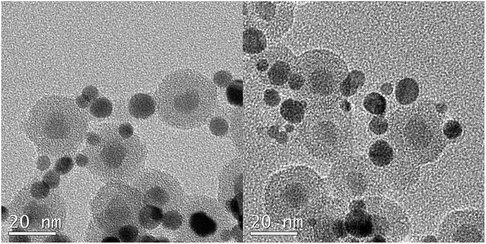 | ||
| Fig. 9 TEM images of Ag/Fe3O4@SiO2 nanoparticles. | ||
The decoration of silver nanoparticles on the Fe3O4@SiO2 core–shell structure causes a further decrease in the magnetic saturation value to 18.2 emu g−1 (Fig. 8), which was attribute to the mass effect of silver and silica. The Ag/Fe3O4@SiO2 nanocomposites showed a strong magnetization which makes it separated by external magnetic field (see Fig. 8 insert image), indicates that this nanocomposites are suitable for magnetic separation and targeting.
The principal of the reduction reaction of 4-nitroaniline to 4-phenylenediamine when using Ag/Fe3O4@SiO2 nanocomposite as the catalysis is showed in Fig. 10. This reaction is considered quite useful in the synthesis of rubber and polymer product42,43 and the catalytic reduction of nitro-compound is well studied.44 The whole reduction reaction could be easily monitored by the UV-vis spectroscopy through the decrease if the strong absorption peaks at 380 nm which could be attribute to 4-nitroanilinate anion. In the Fig. 11, a dramatically decreased of absorption peak at 380 nm when using Ag/Fe3O4@SiO2 as the catalysis, meaning while a peak at 240 nm was appeared and getting stronger with the increase of reaction time which related to the 4-phenylenediamine. Based on the previous report, the reduction reaction happened through the transfer of electrons from the 4-nitroaniline molecules as long as both compounds attached on the surface of Ag/Fe3O4@SiO2 nanocomposites. When the electron transferred to Ag nanoparticles the hydrogen atoms formed and attacked the 4-nitroaniline molecules leading to the occurrence of reduction reaction.45 It is noteworthy that the 4-nitroaniline could be fully reduced within 5 min when using our synthesized Ag/Fe3O4@SiO2 nanocomposites as the catalysis. This phenomenon could be explained by the high surface activity of Ag nanoparticles and the large surface area provided by the small size core–shell nanoparticles. These two characters ensure the Ag/Fe3O4@SiO2 nanocomposites have a good catalytic property. And the TOF value was also calculated to 6 h−1.
 | ||
| Fig. 10 Reaction mechanism about the reducing 4-nitroaniline when using Ag/Fe3O4@SiO2 nanocomposites as the catalysts. | ||
 | ||
| Fig. 11 UV-visible spectra for the reaction of 4-nitroaniline molecule by Ag/Fe3O4@SiO2 nanocomposites at various times. | ||
Another advantage of our synthesized Ag/Fe3O4@SiO2 nanocomposite is high recyclability compared to the single Ag nanoparticles catalysts. The recycling test of Ag/Fe3O4@SiO2 catalysis demonstrated that about 86% of 4-nitroaniline was reduced even after 20 cycles (see Fig. 12). It is worth to note that the nanoparticles start to aggregate after 20 cycles (Fig. S6†) and there were still many Ag nanoparticles located outside the aggregates. The unique core–shell structure makes the nanocomposites highly stable and easily separated by magnet results in a quite well reutilization property compared to other similar studies.46
 | ||
| Fig. 12 The recycling curves of the catalyst Fe3O4@SiO2/Ag for 20 repetitions. | ||
Conclusions
A novel combination of reverse microemulsion system with microwave irradiation route was developed to prepare monodispersed Fe3O4@SiO2 core–shell nanoparticles with a core–shell structure in a very short time. The magnetic nanoparticles were coated by a very thin layer of SiO2 and the dispersity can be controlled by changing the volume of ammonia. On the other hand the number of nanoparticles inside the core could be tuneable through varying the concentration of surfactant (Igepal CO-520). Core–shell nanoparticles were superparamagnetic with a magnetization saturation value of ca. 32% of pure magnetite nanoparticles and the Fe3O4@SiO2 nanoparticles were decorated by Ag nanoparticles. The produced Ag/Fe3O4@SiO2 nanocomposites show nice catalytic efficiency and recycling property up 83% reduction of 4-nitroaniline after 20 cycles. This kind of core–shell structure materials can be also used in biomedical detection, drug delivery and battery system. It is also reasonable to believe that this new stagey is promising in rapid and massive production of various core–shell structure nanoparticles due to its time saving, facile and reliable properties.Acknowledgements
This work was supported by an EU project (Eurotapes, FP7/2007-2013 NMP3-LA2012-280432) and Generalitat de Catalunya (Pla de Recerca 2009-SGR-770 and XaRMAE). We acknowledge the Universitat Autònoma de Barcelona and Institute of Materials Science of Barcelona (ICMAB) in particular Bernat Bozzo and Dr Judith Oro for helping in the characterization of the materials. A pre-doctoral fellowship from the China Scholarship Council is also acknowledged.Notes and references
- S. Laurent, D. Forge, M. Port, A. Roch, C. Robic, L. V. Elst and R. N. Muller, Chem. Rev., 2008, 108, 2064 CrossRef CAS PubMed.
- J. M. Jeong, B. G. Choi, S. C. Lee, K. G. Lee, S. J. Chang, Y. K. Han, Y. B. Lee, H. U. Lee, S. Kwon, G. Lee, C. S. Lee and Y. S. Hun, Adv. Mater., 2013, 25, 6250 CrossRef CAS PubMed.
- J. Fang, B. Zhang, Q. Yao, Y. Yang, J. Xie and N. Yan, Coord. Chem. Rev., 2016, 322, 1 CrossRef CAS.
- J. Qu, F. Ye, D. Chen, Y. Feng, Q. Yao, H. Liu, J. Xie and J. Yang, Adv. Colloid Interface Sci., 2016, 230, 29 CrossRef CAS PubMed.
- L. Liu, F. Ni, J. Zhang, X. Jiang, X. Lu, Z. Guo and R. Xu, Acta Biochim. Biophys. Sin., 2011, 43, 316 CrossRef CAS PubMed.
- L. Wang, J. Luo, S. Shan, E. Crew, J. Yin and C. O. Zhang, Anal. Chem., 2011, 83, 8688 CrossRef CAS PubMed.
- P. Zhang, C. Shao, Z. Zhang, M. Zhang, J. Mu, Z. Guo and Y. Liu, Nanoscale, 2011, 3, 3357 RSC.
- G. C. Rajib and P. Santanu, Chem. Rev., 2011, 112, 2373 Search PubMed.
- L. Z. Tong, J. H. Shi, D. M. Liu, Q. H. Li, X. Z. Ren and H. Yang, J. Phys. Chem. C, 2012, 116, 7153 CAS.
- J. H. Shen, Y. H. Zhu, X. L. Yang, J. Zong and C. Z. Li, Langmuir, 2012, 29, 690 CrossRef PubMed.
- V. M. Masalov, N. S. Sukhinina, E. A. Kudrenko and G. A. Emelchenko, Nanotechnology, 2011, 22, 275718 CrossRef CAS PubMed.
- H. Mohammad-Beigi, S. Yaghmaei, R. Roostaazad, H. Bardania and A. Arpanaei, Phys. E, 2011, 44, 618 CrossRef CAS.
- B. Q. Lu, Y. J. Zhu, G. F. Cheng and Y. J. Ruan, Mater. Lett., 2013, 104, 53 CrossRef CAS.
- J. Zou, Y. G. Peng and Y. Y. Tang, RSC Adv., 2014, 4, 9693 RSC.
- X. M. Ni, Z. Zheng, X. K. Xiao, L. Huang and L. He, Mater. Chem. Phys., 2010, 120, 206 CrossRef CAS.
- W. Stöber, A. Fink and E. Bohn, J. Colloid Interface Sci., 1968, 26, 62 CrossRef.
- T. Tago, T. Hatsuta, K. Miyajima, M. Kishida, S. Tashiro and K. Wakabayashi, J. Am. Ceram. Soc., 2002, 85, 2188 CrossRef CAS.
- J. Lee, Y. Lee, J. K. Youn, H. B. Na, T. K. Yu, H. Kim, S. M. Lee, Y. M. Koo, J. H. Kwak and H. G. Park, Small, 2008, 4, 143 CrossRef CAS PubMed.
- C. Vogt, M. S. Toprak, M. Muhammed, S. Laurent, J. L. Bridot and R. N. Müller, J. Nanopart. Res., 2010, 12, 1137 CrossRef CAS.
- J. Wang, Z. H. Shah, S. Zhang and R. Lu, Nanoscale, 2014, 6, 4418 RSC.
- F. Jiang, Y. Fu, Y. Zhu, Z. K. Tang and P. Sheng, J. Alloys Compd., 2012, 543, 43 CrossRef CAS.
- S. Santra, R. Tapec, N. Theodoropoulou, J. Dobson, A. Hebard and W. Tan, Langmuir, 2001, 17, 2900 CrossRef CAS.
- X. Gao, K. M. K. Yu, K. Y. Tam and S. Chi Tsang, Chem. Commun., 2003, 24, 2998–2999 RSC.
- A. Guerrero-Martínez, J. Pérez-Juste and L. M. Liz-Marzán, Adv. Mater., 2010, 22, 1182 CrossRef PubMed.
- M. Zhang, B. L. Cushing and C. J. O'Connor, Nanotechnology, 2008, 19, 085601 CrossRef PubMed.
- Y. Zhu, F. Y. Jiang, K. Chen, F. Kang and Z. K. Tang, J. Sol–Gel Sci. Technol., 2013, 66, 180 CrossRef CAS.
- H. L. Ding, Y. X. Zhang, S. Wang, J. M. Xu, S. C. Xu and G. H. Li, Chem. Mater., 2012, 24, 4572 CrossRef CAS.
- M. T. C. Fernandes, R. B. R. Garcia, C. A. P. Leite and E. Y. Kawachi, Colloids Surf., A, 2013, 422, 136 CrossRef CAS.
- F. Chen, W. Bu, Y. Chen, Y. Fan, Q. He, M. Zhu, X. Liu, L. Zhou, S. Zhang and W. Peng, Chem.–Asian J., 2009, 4, 1809 CrossRef CAS PubMed.
- C. O. Kappe, Angew. Chem., Int. Ed., 2004, 43, 6250 CrossRef CAS PubMed.
- D. Dallinger and C. O. Kappe, Chem. Rev., 2007, 107, 2563 CrossRef CAS PubMed.
- Y. J. Zhu and F. Chen, Chem. Rev., 2014, 114, 6462 CrossRef CAS PubMed.
- C. Stutz, I. Bilecka, A. F. Thunemann, M. Niederberger and H. G. Borner, Chem. Commun., 2012, 48, 7176 RSC.
- J. C. Park, D. A. Gilbert, K. Liub and A. Y. Louie, J. Mater. Chem., 2012, 22, 8449 RSC.
- J. W. Doolittle Jr and P. K. Dutta, Langmuir, 2006, 22, 4825 CrossRef PubMed.
- K. L. M. Taylor, W. J. Rieter and W. Lin, J. Am. Chem. Soc., 2008, 130, 14358 CrossRef CAS PubMed.
- Z. Chen, S. Li and Y. Yan, Chem. Mater., 2005, 17, 2262 CrossRef CAS.
- S. H. Sun, H. Zeng, D. B. Robinson, S. Raoux, P. M. Rice, S. X. Wang and G. X. Li, J. Am. Chem. Soc., 2004, 126, 273 CrossRef CAS PubMed.
- T. Zhao, N. Goswami, J. Li, Q. Yao, Y. Zhang, J. Wang, D. Zhao and J. Xie, Small, 2016 DOI:10.1002/smll.201601420.
- S. Yang, D. Chen, N. Li, Q. Xu, H. Li, F. Gu, J. Xie and J. Lu, Small, 2016, 12, 360 CrossRef CAS PubMed.
- X. Cui, W. Zuo, M. Tian, Z. Dong and J. Ma, J. Mol. Catal. A: Chem., 2016, 423, 386 CrossRef CAS.
- L. H. Shu and L. Y. Wen, Ann. Occup. Hyg., 2009, 53, 289 CrossRef PubMed.
- I. Yoshiaki and K. Massaaki, J. Health Sci., 2000, 46, 467 CrossRef.
- M. Tian, X. Cui, C. Dong and Z. Dong, Appl. Surf. Sci., 2016, 390, 100 CrossRef CAS.
- B. Naik, S. Hazra, V. S. Prasad and N. N. Chosh, Catal. Commun., 2011, 12, 1104 CrossRef CAS.
- H. Woo, K. Lee, S. Park and K. H. Park, Molecules, 2014, 19, 699 CrossRef PubMed.
Footnote |
| † Electronic supplementary information (ESI) available: Electron diffraction pattern, thermal gravity cure, weight percentage calculation and elements mapping test. See DOI: 10.1039/c6ra19435d |
| This journal is © The Royal Society of Chemistry 2016 |