
NiFe-layered double hydroxides: a bifunctional O2 electrode catalyst for non-aqueous Li–O2 batteries
S. Chitravathi*,
Surender Kumar and
N. Munichandraiah
Department of Inorganic and Physical Chemistry, Indian Institute of Science, Bangalore 560 012, India. E-mail: chitrasgowda@gmail.com
First published on 24th October 2016
Abstract
Ascertaining an appropriate cathode material for the Li–O2 battery system is one of the main tasks at present. To deal with this, in this study, a highly active and stable NiFe-layered double hydroxide (LDH) is synthesized via a hydrothermal method. The characterisation results showed the presence of LDH nanoplates covered with Ni and Fe nanoparticles. In addition to the as prepared NiFe-LDH, its calcinated products at three different temperatures, 300, 500 and 800 °C are also studied for the oxygen reduction reaction (ORR) in a non-aqueous electrolyte by using cyclic voltammetry and rotating disc electrode (RDE) techniques. The as prepared NiFe-LDH exhibits a comparatively greater catalytic activity for ORR than its calcinated products. Li–O2 battery tests are then carried out to further evaluate the catalytic activity of the products in 1.0 M LiPF6 in tetraethylene glycol dimethyl ether (TEGDME). NiFe-LDH exhibited superior catalytic performance with a specific discharge capacity of ∼3218 mA h g−1 at 0.1 mA cm−2. The discharge plateau appears at 2.75 V which is close to theoretical potential (2.9–3.1 V) for Li2O2 formation. A stable specific discharge capacity of ∼1728 mA h g−1 is obtained even after 30 cycles at 0.1 mA cm−2. The discharge–recharge voltage gap is about ∼0.9 V.
1. Introduction
Rechargeable metal–air batteries, in particular nonaqueous lithium–air (Li–O2) batteries, have attracted substantial interest in recent years due to their high theoretical energy density compared to other batteries.1 In a Li–O2 battery, the cell is composed of a Li metal negative electrode, a nonaqueous Li+ electrolyte, and a porous positive electrode. During discharge, O2 from the atmosphere is reduced and combines with Li+ at the positive electrode to produce oxides of lithium. When the cell is charged, the reverse reaction occurs and lithium metal atoms and O2 are regenerated. Current Li–O2 batteries have low charge/discharge efficiency, low power capability, and a short cycle life, which are limited primarily by the reaction kinetics in the air electrode.A highly active bifunctional catalysts is currently needed for Li–O2 batteries. Accordingly, there have been many efforts to develop effective cathodes in order to improve the performance of Li–O2 batteries.2–12 Shao-Horn group reported that catalysts play an important role on the performance of Li–O2 battery.13 Abraham et al., reported a discharge capacity of 4000 mA h g−1 using cobalt phthalocyanine,14 Debart et al., found out that, α-MnO2 nanowires perform better because of its tunnel structure.2 Kumar et al., reported metal nanoparticles decorated graphene sheets as bifunctional catalyst for non-aqueous Li–O2 cells with high discharge capacity,3,4 Lu et al., developed the Pt–Au nanoparticles on Vulcan carbon as catalyst for ORR/OER in non-aqueous Li–O2 cells and reported less voltage gap between charge and discharge for PtAu/C compared to Pt/C.5 Peng et al., studied the effect of morphology of discharge products on the electrochemical performance of Li–O2 batteries during ORR/OER in aprotic solvent,6–8 nitrogen-doped graphene was also reported as a cathode catalyst in Li–O2 cells,9 Ren et al., exposed the effect of heteroatom doping in graphene sheets on the catalytic activity by DFT study,10 Oh et al., synthesized M13 virus-mediated metal oxides with improved cycle life.11 Jian synthesized core–shell structured CNT–RuO2 composite as a high-performance cathode catalyst for rechargeable Li–O2 batteries,12 Choi et al., synthesized Li–O2 batteries with high rate capability and ultra-low overpotential through surface arrangement of Pd–Cu nanocatalysts15 and Kim et al., fabricated flexible binder-free graphene paper cathodes for high-performance Li–O2 batteries.16
Layered double hydroxides (LDHs), also variedly known as anionic clays, have been known for a considerable time. The basic features of their structure, involves positively charged brucite-like cationic layers and weakly bound, often exchangeable, charge-balancing anions located in the interlayer region. The partial isomorphous substitution of trivalent cations for divalent cations results in a net positive charge of the layers. Often, water molecules arising from the crystallization process also associates within these interlayer galleries. Their large interlayer distance may afford remarkable electrochemically accessible surface areas and great electrocatalytic performance.17,18 LDHs have recently drawn great attention in many fields such as catalysis, water splitting, supercapacitors and metal–air batteries due to their catalytic activity, abundance of constituent elements, the ease of preparation and highly tunable compositions.19–24
In this article, we report a nickel-iron layered double hydroxide (NiFe-LDH) with higher catalytic activity and stability towards Li–O2 battery system. Enhanced catalytic activities can be observed because of the incorporated transition metal cations into the brucite-like layers of LDHs. Recently the NiFe-LDH and its derivatives were reported to display good electrocatalytic performances for oxygen evolution reaction (OER),25–29 and also in zinc–air batteries.30,31 Therefore in the present study NiFe-LDH has been used as a promising ORR electrocatalyst for non-aqueous rechargeable Li–O2 battery system for the first time. Using this electrocatalyst a specific discharge capacity of ∼3218 mA h g−1 was obtained with long and stable cycle life.
2. Experimental
2.1. Chemicals
Ni(CH3COO)2·4H2O and Fe(NO3)3·9H2O were obtained from Thomas Baker and Loba Chemie, respectively. Graphite powder (Graphite India), lithium hexafluorophosphate (LiPF6, battery grade > 99.9%), poly(vinylidene fluoride) (PVDF), n-methyl pyrrolidone (NMP), tetraethylene glycol dimethyl ether (TEGDM) and lithium ribbon were obtained from Aldrich. Dimethyl sulphoxide (DMSO, anhydrous, 99.9%), dimethyl formamide (DMF) and tetrabutyl ammonium perchlorate (TBAP) were obtained from SD fine Chemicals High surface area (1500 cm2 g−1) carbon powder was obtained from Fuzhou Yihuan Carbon, Co., China and PTFE suspension from Aldrich, and all the chemicals were used as received. Double-distilled (DD) water was used for all experiments. Required chemicals were immediately stored in glove box filled with purified argon where the moisture and oxygen content was less than 1 ppm.2.2. Synthesis of NiFe-LDH
NiFe-LDH was synthesized by a similar procedure reported elsewhere with little modification.33 In a typical synthesis, 1.6 ml of 0.2 M of Ni(CH3COO)2·4H2O, and 1.6 ml of 0.2 M Fe(NO3)3·9H2O aqueous solution were mixed and vigorously stirred at 80 °C for 4 hours. Then the resulting solution was dispersed in a mixture of 16 ml dimethyl formamide (DMF) and 32 ml of water, transferred to an 80 ml Teflon lined stainless steel autoclave and solvothermally treated at 120 °C for 12 hours. This was followed by another solvothermal treatment at 160 °C for 2 hours. The final product was collected by centrifugation, and repetitively washed with water and lyophilized.2.3. Characterization
The XRD pattern of the NiFe-LDH catalyst was recorded using a Philips ‘X’PERT PRO diffractometer with Cu-Kα radiation (λ: 1.5438 Å) as the X-ray source. The morphology of the catalyst was determined by scanning electron microscopy (SEM, ULTRA 55, GEMINI, Germany) with Energy selective Backscattered (EsB) detector and transmission electron microscopy (TEM) was conducted using a FEI Tecnai T-20 200 kV transmission electron microscope. X-ray photo electron spectroscopy (XPS) was collected on an AXIS ULTRA, 165. The quantification of the metal ions was conducted with a PerkinElmer Optima 2100 DV ICP (Inductively Coupled Plasma) optical emission spectrometer. Charge–discharge cycling of Li–O2 cells was carried out by using Bitrode battery cycling equipment in an air-conditioned room at 22 ± 1 °C.2.4. Electrochemical characterization
The electrochemical performance of the NiFe-LDH as a catalyst of a Li–O2 battery was tested using a Swagelok-type cell. To prepare the cathode, gas diffusion layer (GDL) was prepared using porous carbon paper (Toray) of 2.0 mm thickness which was used as the current collector. A circular (12 mm diameter) disk was punched out of a sheet of Toray carbon paper. High surface area (1500 cm2 g−1) carbon powder and PTFE suspension were mixed in 70![[thin space (1/6-em)]](https://www.rsc.org/images/entities/char_2009.gif) :30 weight ratios. A minimum quantity of water was added to form dough, which was rolled into a layer. This layer was applied on one side of the carbon paper current collector. To prepare the catalyst, NiFe-LDH and PVDF were mixed in 92.5:7.5 ratios in a mortar. A few drops of NMP was added and mixed again to form an ink. The ink was applied on the other side of the carbon paper. The sandwich of GDL, carbon paper and catalyst-layer was pressed in a die at a pressure of 50 kN for 3 min. The electrode was dried at 100 °C for 12 h and transferred into an argon filled MBraun glove box model Unilab. The mass of NiFe-LDH catalyst on the porous carbon paper current collector was in the range of 1.0–1.5 mg. Li–O2 cells were assembled in home-made Swagelok-type PTFE containers. The container had provision to close on one side where Li disk anode was placed and the other side open for exposure to oxygen gas from a cylinder. A Li disk used as the anode (12 mm diameter) was punched out of a ribbon (0.3 mm thick, Aldrich) and its surface was scraped with a knife to remove an outer layer on both sides of it. Stainless steel current collectors were used to take electrical contacts from the electrodes. The Li disk, a glass mat separator and the air electrode were sandwiched inside the PTFE container and stainless steel electric contacts were inserted and sealed. The glass mat was soaked in the electrolyte, made of 1.0 M LiPF6 in TEGDME, before inserting into the cell. The volume of electrolyte was approximately 0.1–0.2 ml. The catalyst layer of the O2 electrode was exposed to the electrolyte and the diffusion-layer to oxygen gas. The discharge/charge operations for the assembled Li–O2 cells were conducted on a Bitrode battery cycling equipment in the voltage range of 1.5–4.5 V vs. Li+/Li under 1.5 bar ultrapure (>99.999%) oxygen gas. The cathode was exposed to 1 atm O2 pressure.3,4
:30 weight ratios. A minimum quantity of water was added to form dough, which was rolled into a layer. This layer was applied on one side of the carbon paper current collector. To prepare the catalyst, NiFe-LDH and PVDF were mixed in 92.5:7.5 ratios in a mortar. A few drops of NMP was added and mixed again to form an ink. The ink was applied on the other side of the carbon paper. The sandwich of GDL, carbon paper and catalyst-layer was pressed in a die at a pressure of 50 kN for 3 min. The electrode was dried at 100 °C for 12 h and transferred into an argon filled MBraun glove box model Unilab. The mass of NiFe-LDH catalyst on the porous carbon paper current collector was in the range of 1.0–1.5 mg. Li–O2 cells were assembled in home-made Swagelok-type PTFE containers. The container had provision to close on one side where Li disk anode was placed and the other side open for exposure to oxygen gas from a cylinder. A Li disk used as the anode (12 mm diameter) was punched out of a ribbon (0.3 mm thick, Aldrich) and its surface was scraped with a knife to remove an outer layer on both sides of it. Stainless steel current collectors were used to take electrical contacts from the electrodes. The Li disk, a glass mat separator and the air electrode were sandwiched inside the PTFE container and stainless steel electric contacts were inserted and sealed. The glass mat was soaked in the electrolyte, made of 1.0 M LiPF6 in TEGDME, before inserting into the cell. The volume of electrolyte was approximately 0.1–0.2 ml. The catalyst layer of the O2 electrode was exposed to the electrolyte and the diffusion-layer to oxygen gas. The discharge/charge operations for the assembled Li–O2 cells were conducted on a Bitrode battery cycling equipment in the voltage range of 1.5–4.5 V vs. Li+/Li under 1.5 bar ultrapure (>99.999%) oxygen gas. The cathode was exposed to 1 atm O2 pressure.3,4
The rotating disk electrode (RDE) experiments were performed with Autolab RDE setup and Autolab potentiostat/galvanostat model PGSTAT 30. The electrochemical cell consisted of traditional three electrode system with a Pt wire pseudo reference electrode in the non-aqueous electrolyte. The cell had inlet and outlet valves for oxygen purging. A glassy carbon disk of 3 mm diameter used as the working electrode was polished with 0.3 μm alumina paste and rinsed thoroughly with double distilled (DD) water and dried carefully prior to the experiments. For the ORR measurement the solution was purged with pure O2 and the effect of sweep rate on the voltammograms were observed at different scan rates from 10 to 85 mV s−1. The rotation speed of RDE was varied in a wide range from 100 to 3000 rpm, while sweeping the potential at 10 mV s−1 in ORR range. All potential values presented in the RDE experiments were converted into standard hydrogen electrode (SHE) scale.
3. Results and discussion
3.1. Characterisation
Fig. 1A shows the XRD pattern of the NiFe-LDH catalyst. It displays the characteristic diffraction peaks corresponding to hydrotalcite-like LDH family, i.e., (003), (006), (012), (015), (018), (110) and (113) at 2θ values 11.24, 22.8, 34.24, 38.66, 45.91, 59.64 and 60.93 degrees, respectively (JCPDF card, no. 51-0463). Three intense characteristic peaks appearing at 2θ angles below 35° corresponding to (003), (006) and (012) planes are sharper, which is attributed to the hydrotalcite structure possessing a greater lattice distance and also well-developed layered stacking with good crystallinity and structural integrity. The presence of (012), (015) and (018) reflections indicates that hydrotalcite has the 3R structure. It is believed that most carbonate-containing LDHs have this structure. In addition the basal spacing value (d003) of LDH phase was 0.78 nm, and c = 2.34 nm which is 3 times the basal spacing proving the stacking sequence 3R consistent with that of carbonate-intercalated LDH materials. The values obtained are in good agreement with the literature data.32–34 | ||
| Fig. 1 (A) XRD pattern of as prepared NiFe-LDH. (B) XRD patterns of as prepared NiFe-LDH and its calcinated catalysts at different temperatures, 300 °C, 500 °C and 800 °C. | ||
Fig. 1B shows the XRD patterns of as prepared NiFe-LDH calcinated at three different temperatures (300, 500 and 800 °C). The characteristic LDH peaks of NiFe-LDH become broad and weak progressively with increasing temperature which is associated with the release of interlayer water, thus resulting in the collapse of brucite-like layers to form mixed oxides. At 300 °C, only a broad and less intense (003) diffraction plane is present and other diffraction planes are diminished. With further increase of temperature to 500 and 800 °C, the intensities of reflections increase and dominant NiO phase at ∼44 and 63 and Fe2O3 phase at ∼35.6 and 57 appear, (JCPDS no. 04-0850).
SEM and TEM images of as prepared NiFe-LDH indicate the formation of LDH-nanoplates or flakes covered with Ni and Fe nanoparticles with an average size of 140 nm uniformly distributed on the plates (Fig. 2A and B). Fig. 3A–D illustrate the EDS mapping of selected area and the elemental maps of Ni and Fe, homogeneously distributed in a nano plate, which confirms the product is indeed NiFe-LDH rather than separated Ni and Fe hydroxides. The EDS spectrum (Fig. 3A) also shows that the final molar ratio of Ni:Fe (1:1.14) is almost the same as the ratio (1:1) of the starting precursors used. In addition, the Ni/Fe ratio in the as prepared NiFe-LDH was further studied by using an elemental analysis method (inductively coupled plasma-optical emission spectroscopy, ICP-OES). It is found that the percentage of Ni and Fe in the as prepared sample is 23.01% and 24.42% respectively having molar ratio of 1:1.06, almost consistent with the results of the EDS analysis.
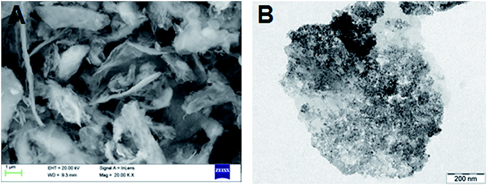 | ||
| Fig. 2 (A) SEM and (B) TEM images of as prepared NiFe-LDH. | ||
 | ||
| Fig. 3 Elemental analysis of the as prepared NiFe-LDH. (A) EDS spectrum, (B) comprehensive image of elemental mappings, (C) and (D) individual mappings of Ni and Fe. | ||
Fig. 4A shows wide XPS spectra of NiFe-LDH which confirms the presence of the Ni, Fe, C and O elements. Presence of O 1s, C 1s, Ni 2p3/2, Fe 2p3/2 multiplets is illustrated in Fig. 4B–E, respectively with curve fitting. In the high resolution spectrum of Ni 2p region (Fig. 4D), the binding energy of the peaks at 859.5 eV and 873.5 eV are attributed to Ni 2p3/2 and Ni 2p1/2 signals, indicating the presence of Ni2+ species in NiFe-LDH. In addition, it is noted that the other two obvious signals located at 863.7 eV and 880.4 eV are assigned to the satellite peaks of Ni 2p3/2 and Ni 2p1/2, respectively, indicative of a high spin Ni2+ state, which confirms the presence of Ni(OH)2 in the NiFe-LDH composite.35 On the other hand, the signals at the binding energy of 713.3 eV and 727 eV corresponding to Fe 2p3/2 and Fe 2p1/2, respectively, indicate the presence of Fe (OH)3. At the same time C 1s shows two peaks with binding energies of 283.6 eV and 286.5 eV may perhaps be due to the different degree of oxidation with metal ions (Ni, Fe) or formation of M–O–C (M![[double bond, length as m-dash]](https://www.rsc.org/images/entities/char_e001.gif) Ni, Fe) bonding via the carboxyl group, leading to large perturbations to the carbon atoms in the carbonyl groups.26 Whereas high intensity O 1s is observed at ∼533 eV, which is associated with the oxygen of the hydroxyl groups on the surface of the NiFe-LDH composite structure.
Ni, Fe) bonding via the carboxyl group, leading to large perturbations to the carbon atoms in the carbonyl groups.26 Whereas high intensity O 1s is observed at ∼533 eV, which is associated with the oxygen of the hydroxyl groups on the surface of the NiFe-LDH composite structure.
 | ||
| Fig. 4 High-resolution XPS spectra of (a) wide range (b) O 1s (c) C 1s, (d) Ni 2p, and (e) Fe 2p for as prepared NiFe-LDH with curve fitting. | ||
Surface area and particle size distribution of the NiFe-LDH is evaluated using the Brunauer–Emmett–Teller (BET) method. Fig. 5 shows the nitrogen adsorption/desorption isotherm and pore-size distribution curve for the as prepared NiFe-LDH. These isotherms belong to type IV with an H3 hysteresis loop, characteristic of slit-like mesoporous structure.36 The measured BET surface area for NiFe-LDH is 175 m2 g−1 and pore width is 5 nm.
 | ||
| Fig. 5 (A) Nitrogen adsorption–desorption isotherm (B) and BJH pore-size distribution plot of the as prepared NiFe-LDH. | ||
3.2. ORR studies in non-aqueous electrolyte
Several aprotic solvents have been studied for Li–O2 battery research like, DMSO, acetonitrile (MeCN), dimethoxyethane (DME), and TEGDME.37–39 In the present study the ORR activity of the as prepared NiFe-LDH catalyst and its calcinated products at 300, at 500 and at 800 °C have been studied and compared towards the reduction properties of oxygen in 0.1 M TBAP/DMSO electrolyte by using cyclic voltammetry (CV) and rotating disk electrode (RDE) voltammetry. All tests are performed in oxygen saturated electrolyte using a three-electrode system. Glassy carbon electrode (GCE) is used as working electrode (3 mm diameter), Pt wire as the reference electrode and Pt foil as auxiliary electrode. The catalysts are dispersed on the glassy carbon disk of a rotating ring-disk electrode (RRDE) with an aerial loading amount of 0.25 mg cm−2.Cyclic voltammetry of as prepared NiFe-LDH coated on GCE is recorded at several sweep rates (10 mV s−1 to 80 mV s−1) in 0.1 M TBAP/DMSO electrolyte and is shown in Fig. 6A. A cathodic peak appears at −1.04 V (Epc) in the forward sweep and an anodic peak in the reverse scan at −0.96 V (Epa) for a scan rate of 10 mV s−1. The reduction peak appearing at −1.04 V is attributed to the reduction of O2 resulting in the formation of TBAO2 as shown in the equation (eqn (1))3,39
| TBA+ + O2 + e− → TBAO2 | (1) |
 | ||
| Fig. 6 (A) Cyclic voltammograms for the reduction of oxygen at different scan rates from 10 to 80 mV s−1 and (B) Randles–Sevcik plot of peak current vs. square root of the scan rate for (i) cathodic and (ii) anodic peak in 0.1 M TBAP/DMSO. | ||
The peak potential separation ΔEp is 80 mV and the charge area ratio (Qa/Qc) under the peaks is almost close to unity. These results indicate that O2 reduction in the presence of TBA+ ions at as prepared NiFe-LDH is reversible. In the Fig. 6A reduction looks to be reversible at all sweep rates, though there is slight shift in peak position. The peak current density is considered to follow Randles–Sevcik equation (eqn (2)).
| ip = (2.69 × 10⁵)n3/2D1/2ν1/2co | (2) |
Fig. 7A displays linear sweep voltammograms (LSVs) recorded in O2 saturated 0.1 M TBAP/DMSO electrolyte solution at several rotation speeds of RDE at 10 mV s−1. For all speeds of RDE, current is negligibly small between 0.02 and −0.65 V due to electron transfer. Reduction current starts increasing at −0.6 V and it is nearly steady between −1.10 and −1.68 V due to diffusion controlled ORR. Current between −0.65 to −1.15 V shows mixed control by both electron transfer and diffusion. RDE data is analyzed by using the Levich equation (eqn (3)), which establishes a relation between limiting current density (iL) at the rotating disk and angular velocity in the limiting current region, i.e. from −1.15 to −1.68 V
| iL = 0.62nFD2/3ν−1/6ω1/2co | (3) |
 | (4) |
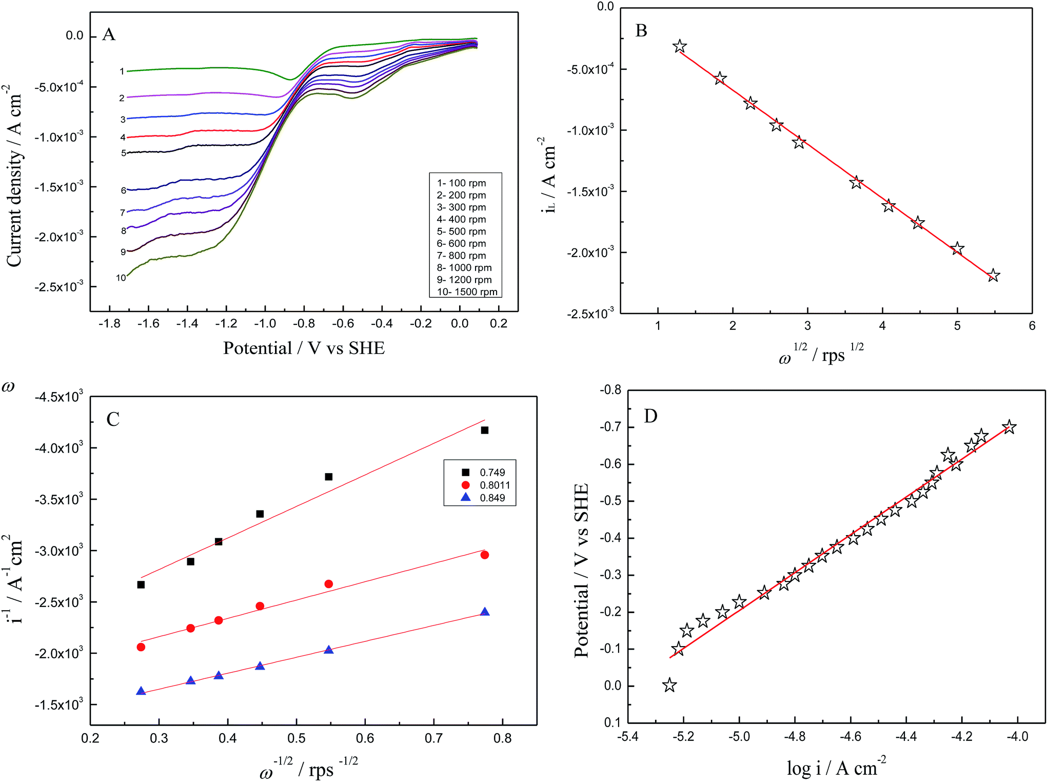 | ||
| Fig. 7 (A) Linear sweep voltammograms collected at various rotation rates (B) Levich plot of limiting current vs. square root of rotation (C) Koutecky–Levich plot and (D) Tafel plot of as prepared NiFe-LDH in oxygenated 0.1 M TBAP/DMSO electrolyte at a scan rate of 10 mV s−1. | ||
Similar experimental procedures as explained for NiFe-LDH as prepared is applied for NiFe-LDH calcinated at 300, 500 and 800 °C towards the reduction properties of oxygen in 0.1 M TBAP/DMSO electrolyte by using CV and RDE technique using GCE. The results show that as prepared NiFe-LDH showed better activity than all the catalysts, which is reflected from the current enhancement from CV and LSV (Fig. 8 and 9) although the decrease in overpotential or oxygen reduction potential is not very clear in LSV as compared to CV. This catalytic activity may be because of the presence of Ni(OH)2 present in as prepared NiFe-LDH especially α-Ni(OH)2 and small percentage of γ-NiOOH which is evident from the basal spacing value (0.78 nm)41 and its catalytic activity towards oxygen reduction reaction which lead to an obvious improvement in the ORR activity relative to the other calcinated samples. On the other hand, a small cathodic peak at ∼0.55 V has appeared which is prominent in as prepared NiFe-LDH and diminishes gradually in the calcinated catalysts tested as LDHs also disappears slowly (see Fig. 1B). This may be due to the presence of different phases of metal ions especially Ni(OH)2 as discussed above. This means that the reduction reaction is influenced greatly by the slight change in the electrode surface according to the applied potential and also that these phases have their own catalytic activity,42 which needs a careful study in future work.
 | ||
| Fig. 8 Comparison of ORR, CV curves at a scan rate of 10.0 mV s−1. | ||
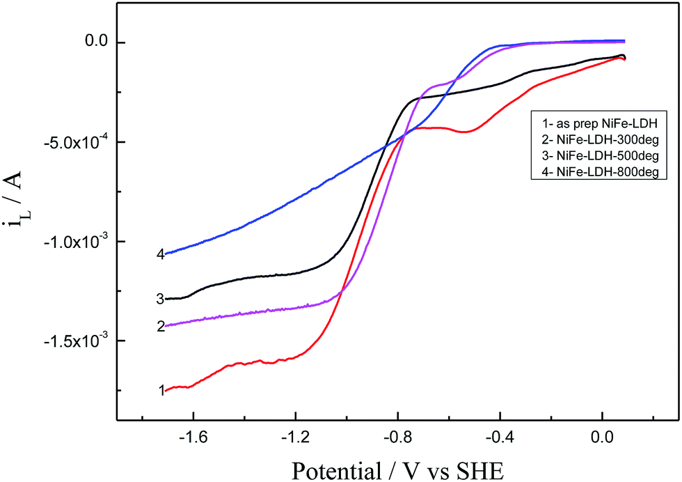 | ||
| Fig. 9 Comparison of ORR, LSV curves at a rotation speed of 1000 rpm at a scan rate of 10.0 mV s−1. | ||
3.3. Li–O2 battery tests
Li–O2 battery tests are then carried out to further evaluate the cathode catalyst performance i.e. as prepared NiFe-LDH in a 1.0 M LiPF6 in TEGDME electrolyte system. The Li–O2 cells are prepared as reported in Section 2.3 and the galvanostatic discharge–charge cycling measurements are carried out between the potential window 4.5–1.5 V versus Li/Li+. Fig. 10 shows the initial discharge–charge voltage profile of Li–O2 battery using as prepared NiFe-LDH cathode at a current density of 0.1 mA cm−2. The cell showed an average discharge voltage of about 3.55 V. The discharge and charge capacities of as prepared NiFe-LDH were ∼3218 and ∼3460 mA h g−1 respectively. The ratio of charge and discharge capacities suggests that the Li–O2 cell can be totally recharged. A large and flat discharge plateau at around ∼2.75 V vs. Li/Li+ was obtained due to the formation of Li2O2. The corresponding charge plateau is obtained at ∼3.65 V vs. Li/Li+. The discharge–charge voltage gap was about ∼0.9 V. The obtained discharge–charge voltage gap is considerably less than most of the reported cathodes for Li–O2 batteries in ether based electrolyte.43,44 This could be due to the catalytic activity of as prepared NiFe-LDH. After the first cycle, cell showed a rapid fading of discharge capacity to about 43% for about 4 cycles, and then discharge capacity decreased to about 48% for the rest of the 30 cycles. The curves are very much reversible except for a minor change in shape between the first discharge–charge cycle and for 30th cycle. This may be due to the change in the structure of the catalyst during expansion and contraction. | ||
| Fig. 10 Discharge and charge capacity of Li–O2 battery using as prepared NiFe-LDH under 0.1 mA cm−2 current density and 1 atm O2 pressure. | ||
It is known that discharge current density affects the specific capacity of the Li–O2 cell. The rate capability of Li–O2 (NiFe-LDH) battery at different current densities i.e. 0.1, 0.2, 0.3, 0.4 and 0.8 mA cm−2 is studied as shown in Fig. 11. This shows that upon increasing the current, the specific capacity decreases for all the investigated current densities which may be due to the high ion-conductivity. However Li–O2 (NiFe-LDH) battery showed good rechargeability at all current densities. The discharge–charge voltage gap increases with the increase in current density value.
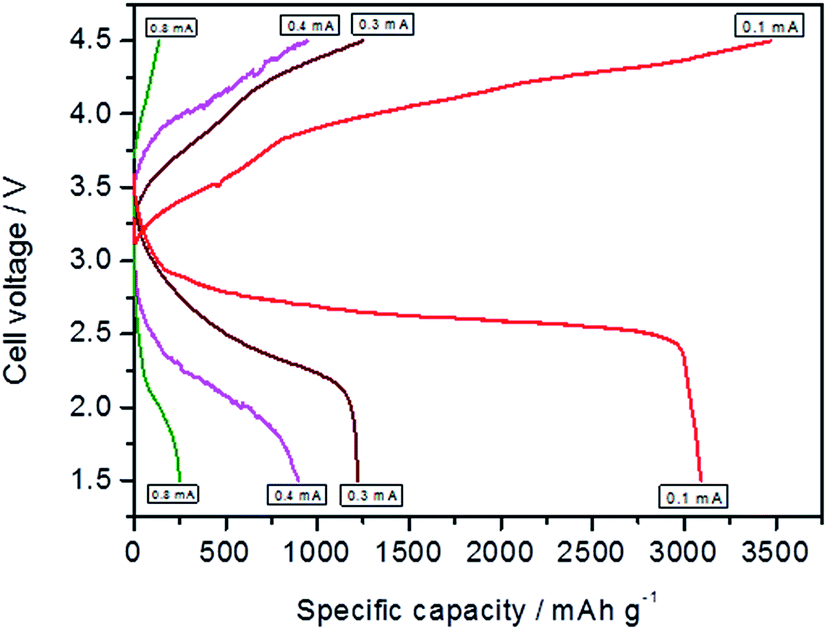 | ||
| Fig. 11 Comparison of discharge and charge capacity of first cycle using as prepared NiFe-LDH at different current densities of Li–O2 battery under 1 atm O2 pressure. | ||
Cycle stability is an important issue for Li–O2 batteries. Fig. 12 demonstrates specific discharge capacity vs. cycle number for cells discharged and charged for 30 cycles with voltage cut-off of 1.5 V (discharge) and 4.5 V (charge) at different current densities i.e. 0.1, 0.2, 0.3, 0.4 and 0.8 mA cm−2. The cells as explained above showed rapid capacity fading for about 4 to 5 cycles at all current densities and then a stable discharge capacity up to 30 cycles without significant capacity loss is observed.
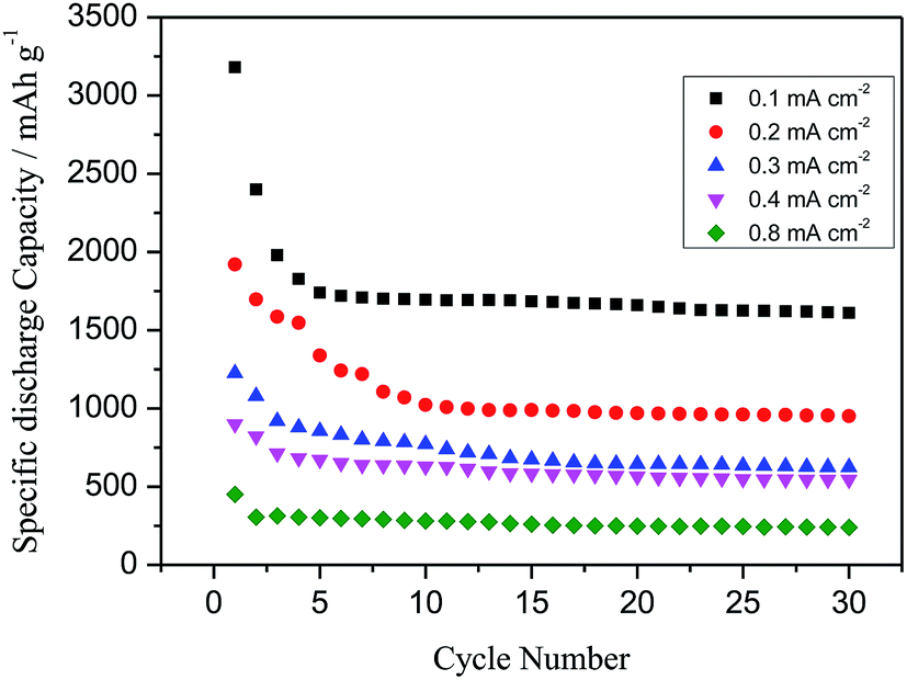 | ||
| Fig. 12 Cycle stability of as prep. NiFe-LDH at different current densities. | ||
Li–O2 battery performance of calcinated products of NiFe-LDH is also investigated at a current density of 0.4 mA cm−2 which showed that, as prepared NiFe-LDH showed best electrocatalytic activity compared to NiFe-LDH-300 °C and NiFe-LDH-500 °C. As shown in the Fig. 13 discharge and charge capacity decreases in the order of as prepared NiFe-LDH > NiFe-LDH-300 °C > NiFe-LDH-500 °C, whereas NiFe-LDH-800 °C catalyst didn't show any battery performance. This is in accord with the fact that the metal hydroxides or oxy hydroxides are generally the active sites. We further extended the battery test by investigating the cycling stability of as prepared NiFe-LDH and its calcinated products, for 100 cycles at a current density of 0.4 mA cm−2. It is inferred from the result that although discharge capacity decreases consistently, it never reaches zero capacity. Even though all the three catalysts showed fairly stable capacity for initial 40 to 50 cycles, the as prepared NiFe-LDH catalyst showed superior catalytic activity and stability towards Li–O2 battery system. This may be because of the incorporated Ni hydroxides accompanied with Fe in the LDHs. This shows that Li–O2 cells with NiFe-LDH catalyst in 1 M LiPF6/TEGDME can sustain more than 100 cycles with justifiable capacity.
 | ||
| Fig. 13 Comparison of discharge and charge capacity of first cycle of (1) as prepared NiFe-LDH, (2) NiFe-LDH-300 °C and (3) NiFe-LDH-500 °C at a current density 0.4 mA cm−2. | ||
With the purpose of identifying the reaction products after discharging of NiFe-LDH in 1 M LiPF6/TEGDME electrolyte, a Li–O2 cell which was terminated at the 16th discharge cycle is dissembled and XRD pattern is recorded. Fig. 14 shows the XRD pattern of the 16 cycle discharged cathode. The peak at 2θ equal to 18.1° is attributed to the PTFE binder present in the electrode, the peak at 26.2° is due to carbon present in the GDL of the cathode. The peaks at around 31.4, 35.2 and 73.0° are due to Li2O2, and peaks at 49.0 and 54.4° are due to Li2O. Low intensity peaks at around 12.0 and 42.0° are due to α-Ni(OH)2.45 The XRD data verifies the presence of Li2O2 and Li2O even after 16th cycle showing that there is little or no evidence of other discharge products as TEGDME is relatively stable to superoxide attack and a potential of ∼3.55 V would be sufficient to charge a battery. Several recent literatures have also examined the stability of carbon cathode in non-aqueous Li–O2 batteries.46,47 Thus, Li2O2 and Li2O are inferred as the products of O2 reduction in the present study.
 | ||
| Fig. 14 XRD pattern of oxygen electrode of Li–O2 (as prepared NiFe-LDH) cell after subjecting to sixteen charge–discharge cycles. | ||
4. Conclusion
In this study, we reported an improved Li–O2 battery that exhibited a lower voltage gap between discharge and charge and better cycle performances using NiFe-LDH as a promising catalyst. This stability was provided by the inorganic coverage offered by the LDH layers. Thermal treatment might have caused the collapse of the layered structure, with consequent formation of mixed metal oxides. Furthermore, the battery was tested under various cycling systems. In conclusion, this result, although preliminary opens-up the possibilities of using layered double hydroxides for Li–O2 battery systems in 1 M LiPF6/TEGDME electrolyte. This type of catalysts can be used for rechargeable Li–O2 battery by optimising the kind of metal hydroxides used in the LDHs for the better performance.Acknowledgements
The authors wish to acknowledge the financial support given by Dr D. S. Kothari Post-Doctoral Fellowship scheme under UGC, INDIA.References
- G. Girishkumar, B. McCloskey, A. C. Luntz, S. Swanson and W. Wilcke, J. Phys. Chem. Lett., 2010, 1, 2193–2203 CrossRef CAS.
- A. Debart, A. J. Paterson, J. Bao and P. G. Bruce, Angew. Chem., Int. Ed., 2008, 47, 4521–4524 CrossRef CAS PubMed.
- S. Kumar, C. Selvaraj, N. Munichandraiah and L. G. Scanlon, RSC Adv., 2013, 3, 21706–21714 RSC.
- S. Kumar, C. Selvaraj, L. G. Scanlon and N. Munichandraiah, Phys. Chem. Chem. Phys., 2014, 16, 22830–22840 RSC.
- Y.-C. Lu, Z. Xu, H. A. Gasteiger, S. Chen, K. Hamad-Schifferli and Y. Shao-Horn, J. Am. Chem. Soc., 2010, 132, 12170–12171 CrossRef CAS PubMed.
- J. Wang, Y. Zhang, L. Guo, E. Wang and Z. Peng, Angew. Chem., Int. Ed., 2016, 55, 5201–5205 CrossRef CAS PubMed.
- Y. Zhang, X. Zhang, J. Wang, W. C. McKee, Y. Xu and Z. Peng, J. Phys. Chem. C, 2016, 120, 3690–3698 CAS.
- Y. Zhang, Q. Cui, X. Zhang, W. C. McKee, Y. Xu, S. Ling, H. Li, G. Zhong, Y. Yang and Z. Peng, Angew. Chem., Int. Ed., 2016, 55, 10717–10721 CrossRef CAS PubMed.
- G. Wu, N. H. Mack, W. Gao, S. Ma, R. Zhong, J. Han, J. K. Baldwin and P. Zelenay, ACS Nano, 2012, 6, 9764–9776 CrossRef CAS PubMed.
- X. Ren, B. Wang, J. Zhu, J. Liu, W. Zhang and Z. Wen, Phys. Chem. Chem. Phys., 2015, 17, 14605–14612 RSC.
- D. Oh, J. Qi, B. Han, G. Zhang, T. J. Carney and J. Ohmura, Nano Lett., 2014, 14, 4837–4845 CrossRef CAS PubMed.
- Z. Jian, P. Liu, F. Li, P. He, X. Guo and M. Chen, Angew. Chem., Int. Ed., 2014, 53, 442–446 CrossRef CAS PubMed.
- Y.-C. Lu, H. A. Gasteiger, M. C. Parent, V. Chiloyan and Y. Shao-Horn, Electrochem. Solid-State Lett., 2010, 13, A69–A72 CrossRef CAS.
- K. M. Abraham and Z. Jiang, J. Electrochem. Soc., 1996, 143, 1–5 CrossRef CAS.
- R. Choi, J. Jung, G. Kim, K. Song, Y. I. Kim and S. C. Jung, Energy Environ. Sci., 2014, 7, 1362–1368 CAS.
- D. Y. Kim, M. Kim, D. W. Kim, J. Suk, O. O. Park and Y. Kang, Carbon, 2015, 93, 625–635 CrossRef CAS.
- F. Cavani, F. Trifiro and A. Vaccari, Catal. Today, 1991, 11, 173–301 CrossRef CAS.
- D. G. Evans and R. C. T. Slade, Struct. Bonding, 2006, 119, 1–87 CAS.
- C. Nyambo, P. Songtipya, E. Manias, M. M. Jimenez-Gasco and C. A. Wilkie, J. Mater. Chem., 2008, 18, 4827–4838 RSC.
- A. C. S. Alcântara, P. Aranda, M. Darder and E. R. Hitzky, J. Mater. Chem., 2010, 20, 9495–9504 RSC.
- J. Zhao, J. Chen, S. Xu, M. Shao, Q. Zhang, F. Wei, J. Ma, M. Wei, D. G. Evans and X. Duan, Adv. Funct. Mater., 2014, 24, 2938–2946 CrossRef CAS.
- Y. Wang, W. Yang, C. Chen and D. G. Evans, J. Power Sources, 2008, 184, 682–690 CrossRef CAS.
- S. Huang, G. N. Zhu, C. Zhang, W. W. Tjiu, Y. Y. Xia and T. Liu, ACS Appl. Mater. Interfaces, 2012, 4, 2242–2249 CAS.
- X. Xiang, F. Li and Z. Huang, Reviews in Advanced Sciences and Engineering, 2014, 3, 158–171 CrossRef.
- K. Yan, T. Lafleur, J. Chai and C. Jarvis, Electrochem. Commun., 2016, 62, 24–28 CrossRef CAS.
- X. Long, J. Li, S. Xiao, K. Yan, Z. Wang, H. Chen and S. Yang, Angew. Chem., Int. Ed., 2014, 53, 7584–7588 CrossRef CAS PubMed.
- D. A. Corrigan, J. Electrochem. Soc., 1987, 134, 377–384 CrossRef CAS.
- X. Li, F. C. Walsha and D. Pletcher, Phys. Chem. Chem. Phys., 2011, 13, 1162–1167 RSC.
- M. Gong, Y. Li, H. Wang, Y. Liang, J. Z. Wu, J. Zhou, J. Wang, T. Regier, F. Wei and H. Dai, J. Am. Chem. Soc., 2013, 135, 8452–8455 CrossRef CAS PubMed.
- Y. Y. Liang, H. L. Wang, P. Diao, W. Chang, G. S. Hong, Y. G. Li, M. Gong, L. M. Xie, J. G. Zhou and J. Wang, J. Am. Chem. Soc., 2012, 134, 15849–15857 CrossRef CAS PubMed.
- Y. Li, M. Gong, Y. Liang, J. Feng, J. E. Kim, H. Wang, G. Hong, B. Zhang and H. Dai, Nat. Commun., 1805, 2013, 4 Search PubMed.
- H. F. W. Taylor, Mineral. Mag., 1973, 39, 377–389 CAS.
- J. Wang, G. L. Fan and F. Li, RSC Adv., 2012, 2, 9976–9985 RSC.
- S. Nayak, L. Mohapatra and K. Parida, J. Mater. Chem. A, 2015, 3, 18622–18635 CAS.
- C. O. Laoire, S. Mukerjee, K. M. Abraham, E. J. Plichta and M. A. Hendrickson, J. Phys. Chem. C, 2009, 113, 20127–20137 CAS.
- M. Kruk and M. Jaroniec, Chem. Mater., 2001, 13, 3169–3183 CrossRef CAS.
- L. Johnson, C. Li, Z. Liu, Y. Chen, S. A. Freunberger, P. C. Ashok, B. B. Praveen, K. Dholakia, J. M. Tarascon and P. G. Bruce, Nat. Chem., 2014, 6, 1091–1099 CrossRef CAS PubMed.
- J. Scheers, D. Lidberg, K. Sodeyama, Z. Futera and Y. Tateyama, Phys. Chem. Chem. Phys., 2016, 18, 9961–9968 RSC.
- C. O. Laoire, S. Mukerjee and K. M. Abraham, J. Phys. Chem. C, 2010, 114, 9178–9186 CAS.
- A. J. Bard and L. R. Faulkner, Electrochemical Methods: Fundamentals and Applications, John Wiley & Sons, New York, 1980 Search PubMed.
- M. Vidotti, R. Torresi and S. I. Córdoba de Torresi, Quim. Nova, 2010, 33, 2176–2186 CrossRef CAS.
- K. Matsuki and H. Kamada, Electrochim. Acta, 1986, 31, 13–18 CrossRef CAS.
- S. A. Freunberger, Y. Chen, N. E. Drewett, L. J. Hardwick, F. Bard and P. G. Bruce, Angew. Chem., Int. Ed., 2011, 50, 8609–8613 CrossRef CAS PubMed.
- C. O. Laoire, S. Mukerjee, E. J. Plichta, M. A. Hendrickson and K. M. Abraham, J. Electrochem. Soc., 2011, 158, A302–A308 CrossRef CAS.
- H. Zhang, X. Zhang, D. Zhang, X. Sun, H. Lin, C. Wang and Y. Ma, J. Phys. Chem. B, 2013, 117, 1616–1627 CrossRef CAS PubMed.
- B. D. McCloskey, D. S. Bethune, R. M. Shelby, G. Girishkumar and A. C. Luntz, J. Phys. Chem. Lett., 2011, 2, 1161–1169 CrossRef CAS PubMed.
- W. Xu, J. Hu, M. H. Engelhard, S. A. Towne, J. S. Hardy, J. Xiao, J. Feng, M. Y. Hu, J. Zhang, F. Ding, M. E. Gross and J. G. Zhang, J. Power Sources, 2012, 215, 240–247 CrossRef CAS.
| This journal is © The Royal Society of Chemistry 2016 |