DOI:
10.1039/C6RA19026J
(Paper)
RSC Adv., 2016,
6, 86520-86530
Effect of nanoparticles on fibril formation and mechanical performance of olefinic block copolymer (OBC)/polypropylene (PP) microfibrillar composites
Received
27th July 2016
, Accepted 5th September 2016
First published on 5th September 2016
Abstract
The morphology and properties of olefin block copolymer (OBC)/polypropylene (PP) microfibrillar composites (MFCs) were tuned by adding nano silica (SiO2) and carbon nanotubes (CNTs) respectively. When the two nanoparticles (NPs) located in the OBC matrix, refined microfibrils were maintained and the final diameters of the PP microfibrils slightly increased compared to the un-modified MFCs; when the NPs located in the dispersed PP component, they exerted a profound impact on the deformation of PP during the fibrillation process. The CNTs can still lead to refined PP microfibrils while addition of SiO2 induces a transition of PP morphology from fibrillar to nodular and even to a spherical structure as its content increases from 0.3 wt% to 1 wt%. The rheological and mechanical properties were also influenced by the type and selective dispersion of NPs. In particular, if the fibrillar morphology of PP was kept in the ternary composites, a small amount of nanoparticles could lead to synergetic enhancement, with polypropylene microfibrils, on the tensile properties of OBC. This work provides a better understanding of the role of NPs in the fiber formation process and an alternative way to control the morphological evolution of MFCs.
1. Introduction
Microfibrillar composites (MFCs) are in situ generated from polymer blends during polymer processing, in which the polymer matrix is reinforced with high aspect ratio microfibrils of a different polymer.1–6 The fabrication process of the composites usually contains three steps.7,8 First, melt blending (extruding) is performed to disperse the minor phase in the matrix. A second step, namely the fibrillation step, includes drawing the obtained extrudates to fibrillate the dispersed component. During this step, the fibrillar morphology depends on the ratio between shear force and interfacial force.9,10 Finally, the semi-finished oriented blend is processed by injection or compression molding between the melting temperatures of the two polymers. The mechanical properties of the MFCs can be improved noticeably since the dispersed phase in situ generates reinforcing microfibrils during processing. Therefore, the development of MFCs provides an alternative and promising way to fabricate fiber reinforced composites. The processing method is convenient with low cost. Especially, MFCs do not require the dispersion of preformed reinforcing fibers (e.g. natural fibers, aramid fibers and carbon fibers) into the matrix because the microfibrils are formed in situ, thus avoiding the dispersion of the agglomerated fibers. Another prominent advantage of MFCs is the method provides a technology to complete recycle the waste plastic mixtures where both low melting temperature general polymers and high melting temperature plastics co-exist and cannot be easily separated.11 Even more interesting is that, if the matrix can crystallize, high interfacial bonding of the fibrils could be realized via the formation of a transcrystalline layer of the matrix around the fibrils, avoiding complicated and costly surface modifications of the nanoparticles.12–15
Normally, the fibrillar structures are tuned by the viscosity ratio of the two polymers, interfacial interactions and external processing parameters, like post stretch ratios. Recently, nanoparticles (NPs) are also used to modify the fibrillar structures.16–22 Due to the differed shapes and topological structures of different NPs, the viscoelastic property of the melt fluid is also varied, which plays an important role in determining the morphological evolution of the dispersed component. Based on the review of the related literatures, the adding of NPs could facilitate or hinder the fibrillation process depending on the used NPs. Although all the authors have delivered some explanations on the deformation mechanism of fibrillated polymer in their respective researches, it is also critical to comprehensively compare different NPs at the same time. In this way, one could seek for more reliable and intuitional proofs on exactly how NPs affect the fibrillation process (positive or negative) in different circumstances. Regrettably, such comparative study has not been reported yet.
Among the NPs used to modify MFCs, nanosilica (SiO2) and multiwall carbon nanotubes (CNTs) are commonly used as isotropic and anisotropic fillers respectively and have different impact on viscoelastic property of polymer melt. In our previous study, in our previous study, the diameters of PP fibrils were proved to be independent of PP content (less than 20 wt%) and 10 wt% of PP displayed balanced reinforcement of tensile strength and flexibility on the matrix elastomer. Therefore here, the weight ratio is fixed at 90/10 so as to focus on how the nanoparticles affect the MFCs.23,24 In this work, the two NPs were added into the blends and the effect of the fillers on the formation of fiber structures was thoroughly investigated and compared via controlling the content and location of the fillers.
2. Materials and methods
2.1 Materials
OBC was supplied by Dow Chemical Company. The commercial type is 9500 with an octene content of 12.9%. The hard and soft segment is 25% and 75% respectively. PP powder is the commercial product of Baota Petrochemical Group, China and has a melt flow index of 20 g/10 min. Hydrophobic silica nanoparticles (Aerosil R974) with a primary diameter of 12 nm were kindly supplied by Chengdu Taly industrial chemical Co., Ltd of China. Multi-walled carbon nanotubes (CNTs), under the trade name of NC 7000 was produced by Nanocyl S.A (Belgium). The average diameter and length is 9.5 nm and 1.5 μm respectively.
2.2 Sample preparation
The OBC/PP/NPs ternary nanocomposites were fabricated using one-step and two-step method respectively. For the one-step method, nanoparticles were blended with PP powders and OBC directly in the extruder equipped with a convergent die at 50 rpm. The temperature profile from hopper to die of the extruder was 110, 180, 180 and 175 °C. The extruded melt with the OBC/PP/NPs 90/10/X (X = 0.3, 0.5 and 1) w/w/w composition was drawn using an adjustable taken-up device. For the two-step method, PP powders and NP were preliminarily mixed by stirring in high speed, followed by further mixing in a Hakke internal mixer at a temperature of 180 °C and a rotor speed of 50 rpm for 10 min. The premixed composites of PP and NP were then compounded with OBC using the above extrusion-stretching method. The sample notations and composition of the composites are presented in Table 1.
Table 1 Sample notation and composition of OBC/PP MFCs nanocomposites
| Samples |
OBC |
PP |
CNTs |
SiO2 |
I(II) |
| 0.3C-I(II) |
90 |
10 |
0.3 |
0 |
One-step (two-step) |
| 0.5C-I(II) |
90 |
10 |
0.5 |
0 |
One-step (two-step) |
| 1C-I(II) |
90 |
10 |
1 |
0 |
One-step (two-step) |
| 0.3S-I(II) |
90 |
10 |
0 |
0.3 |
One-step (two-step) |
| 0.5S-I(II) |
90 |
10 |
0 |
0.5 |
One-step (two-step) |
| 1S-I(II) |
90 |
10 |
0 |
1 |
One-step (two-step) |
2.3 Flow behavior of PP/NP binary composites
The apparent viscosity was measured by an Advanced Capillary Rheometer (RH7, Germany). The diameter of the capillary die was 1 mm, and its L/D ratio was 30![[thin space (1/6-em)]](https://www.rsc.org/images/entities/char_2009.gif) :1. The testing temperature was set at 180 °C. The shear rates varied from 10 to 2000 s−1.
:1. The testing temperature was set at 180 °C. The shear rates varied from 10 to 2000 s−1.
2.4 Shear rheological measurements
The linear viscoelastic behaviors of pure OBC, PP/NPs blends and OBC/PP/NPs microfibrillar composites were studied using the parallel-plate geometry, with a diameter of 25 mm and 1 mm between the plates. The strain amplitude was set as 1% with the frequency sweep performed in the range of 0.06–628 rad s−1. For PP/NP binary composites, the testing temperature was 180 °C. Whereas for the microfibrillar composites, the test was performed at 140 °C, which was above OBC's melting point and yet low enough to prevent PP microfibrils from melting.
2.5 Scanning electron microscope (SEM)
The scanning electron microscopy (SEM) experiments were performed using an FEI Inspect F SEM instrument with an acceleration voltage of 20 kV. The selective dispersion of NP in the microfibrillar composites was determined from the cross-section of the extruded strip. To expose the PP component and distinguish it from the matrix, the cryo-fractured samples were etched chemically in xylene at 70 °C for 30 min to slightly remove OBC matrix, followed by washing and drying. The overall view of PP morphology was also observed by SEM after OBC matrix was totally removed by hot xylene at 80 °C for 3 hours.
2.6 Atomic force microscopy (AFM)
The cross-section of the extruded strip was cryomicrotomed using a Leica microtome at −80 °C. The samples were observed with an atomic force microscope (AFM) operating in tapping mode using an instrument with a SPI4000 Probe Station controller (SIINT Instruments, Japan) at room temperature. Phase contrast images were collected.
2.7 Thermogravimetric analysis (TGA)
The OBC matrix of the MFCs was completely removed by xylene and the remaining PP fibrils were collected for the TGA test (Q500 TA Instruments) at nitrogen atmosphere. 5 mg of the testing samples were heated to 700 °C at 10 °C min−1. In addition, the TGA results of MFCs without the etching process were also carried out for comparison.
2.8 Tensile test
The tensile properties of the MFCs were measured at room temperature using an Instron 4302 universal tensile test. Tensile measurements were made on dumbbell shape specimens 4 mm wide, 2 mm thick with a gauge length of 20 mm. A crosshead speed of 50 mm min−1 was applied to determine the tensile properties.
3. Results and discussion
3.1 Dispersion of NP in OBC/PP blends
In this article, the ternary MFCs were fabricated through two strategies. Therefore, it is critical to determine how the NPs were dispersed in the two situations. From the theoretical point of view, the localization of nanoparticles in OBC/PP blends can be qualitatively predicted by using the wetting parameter ω. According to Young's equation, the wetting coefficient ω,25| |
 | (1) |
If ω > 1, NP would be preferentially localized in the PP phase; if ω < −1, NP are predicted to disperse in the OBC phase; if the value of ω is between −1 and 1, NP favor to locate at the interface of the two polymers. In eqn (1), γ is the interfacial energy between the two polymers or polymer and filler, which can be estimated by the harmonic-mean equation and geometric-mean equation, respectively.26
| |
 | (2) |
| |
 | (3) |
where
γ1 and
γ2 are the surface tensions of OBC and PP respectively.
γd1 and
γd2 are the dispersion parts of the surface tensions.
γp1 and
γp2 represent the polar parts. Generally, these values are determined by a contact angle test at room temperature. Surface tensions at processing temperature (180 °C) could be calculated by extrapolating the values at room temperature using the following equations.
27,28| |
 | (4) |
where
γ0 represents the surface free energy at 0 °C and
Tc is the critical temperature (
Tc is 1000 K for polymers).
29
The values for the surface tensions (listed in Table 2) of OBC/PP, SiO2 and CNTs were taken from literatures.26,30,31 Based on eqn (4), the values of OBC and PP at our processing temperature 180 °C were calculated using the data in ref. 43, where the values were given at 190 °C. Besides, the surface tensions of SiO2 and CNTs are assumed to be independent of temperature.29,32 The wetting coefficients (ω) are thus calculated using the harmonic-mean equation and geometric-mean equation respectively (see Table 3).
Table 2 Surface tension at 180 °C
| Materials |
Surface tension (mN m−1) |
| Total (γ) |
γd |
γp |
| OBC |
17.76 |
15.84 |
1.92 |
| PP |
22.03 |
21.52 |
0.51 |
| SiO2 |
13.1 |
13.1 |
0 |
| CNTs |
27.8 |
17.6 |
10.2 |
Table 3 Calculated ω at 180 °C
| Calculation method |
Interfacial energies (mN m−1) |
ω (mN m−1) |
| γOBC/NP |
γPP/NP |
γOBC/PP |
| SiO2 |
Harmonic-mean equation |
2.18 |
2.56 |
1.68 |
−0.23 |
| Geometric-mean equation |
2.0 |
1.55 |
0.89 |
0.57 |
| CNTs |
Harmonic-mean equation |
5.75 |
9.16 |
1.68 |
−2.02 |
| Geometric-mean equation |
3.32 |
6.35 |
0.89 |
−3.4 |
According to the two methods, the ω value of SiO2 lies between −1 and 1, indicating that the hydrophobic silica particles prefer to locate at the interface of the two polymers; for CNTs, the ω value is smaller than −1, which indicates they will be only present in the OBC phase. However, if the viscosity of the melt is high and the processing time is relatively short, the thermodynamic equilibrium state is difficult to be achieved and kinetic factors like blending procedures, blending time, NP content and shear strength may also dominate the particle distribution.33 In our system, NPs were located in the OBC and PP component for the one- and two-step method respectively at the beginning of the extrusion process. There are only small differences in surface energy and polarity of the polymers and NPs, it would be difficult for NPs to migrate from one phase to another. After extruding, NPs would prefer to maintain the original dispersion state.
To confirm the theoretical result, the selective dispersion of NP is proved by SEM, AFM and TGA. Fig. 1 displays the micrographs of the cross-section of the extruded strip. When the composites are compounded by two-step methods, both SiO2 and CNTs can be observed inside the microfibrillar PP phase; whereas when added by one-step, the NPs are mainly dispersed in the OBC matrix. Unfortunately, the OBC matrix was partially etched to expose the PP fibrils, it is difficult to discriminate the nanoparticles from the matrix. To overcome the drawbacks, AFM phase images are also obtained as illustrated in Fig. 2. The round dark areas represent the cross-section of PP fibrils of higher modulus. For the composites compounded by one-step, CNTs (pointed by the red arrow) are mainly dispersed in the OBC matrix which is in agreement with the wetting parameter. For SiO2, instead of aggregating at the interface of the two polymers based on the thermodynamic prediction, SiO2 also is located in the OBC phase because the viscosity of OBC is higher than PP and the mixing time is limited, making it difficult for SiO2 to migrate from OBC toward PP. When the nanoparticles were mixed by the two-step method, most of NPs stayed in PP component with several CNTs or tiny SiO2 aggregates dispersed outside PP. Because at the beginning of the extrusion process, the content of NPs in PP component is relative high (from 3 wt% to 10 wt%), the migration of NPs from PP to OBC is inevitable and the migration was expected to be more evident at higher NP loadings.
 |
| | Fig. 1 SEM micrographs of the cryo-fractured surface of the strip extrudate, after the matrix was gently etched by xylene. | |
 |
| | Fig. 2 AFM phase images of the cryo-fractured surface of the strip extrudate (the red arrows point at dispersed CNTs and SiO2). | |
To roughly estimate the actual filler content in the MFCs, a TGA test was conducted on the samples of the composites with 0.5 wt% SiO2 and CNTs. As shown in Fig. 3, the OBC matrix was totally removed by solvent, after which the remaining PP component was cleaned and dried for the TGA test. The residual carbon content of 0.5C-II-E and 0.5S-II-E is around 6%, which is higher than that of 0.5C-I-E and 0.5S-I-E. This proves that the pre-mix of nanoparticles with PP realizes the selective location of both SiO2 and CNTs in the PP component. Theoretically, the residual content of 0.5C-I-E and 0.5S-I-E is lower than its un-etched (NE) counterpart since the nanoparticles are supposed to disperse in the OBC matrix which was etched away before the TGA test. The possible reason may be that when OBC was dissolved in the xylene solvent, some of the dispersed nanoparticles would be absorbed on the surface of the PP phase. That results in the relative higher residual percentage (3%) of 0.5C-I-E and 0.5S-I-E.
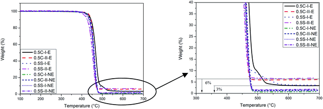 |
| | Fig. 3 The thermal gravimetric curves of the nanocomposites filled with 0.5% of nanoparticles. NE: none etched samples (extruded strip); E: the extruded samples are etched by xylene until OBC matrix is totally removed. The residual samples are tested. | |
3.2 Morphology of PP
The effect of the discussed selective dispersion of NP on the morphology of PP was fully displayed by SEM. Fig. 4 displays the micrograph of PP microfibrils and the diameter distributions. The average diameters of the microfibrils are illustrated in Fig. 5. Before the nanoparticles were added, PP could be transformed into tiny micro and even nano fibrils with an average diameter of 100 nm. The addition of nanoparticles, whether SiO2 or CNTs, results in the increase of the fibril diameters. However, the different mixing strategies exert different influences on the final morphology of PP. When using the one-step method, the addition of the two nanoparticles lead to a slight increase of the fibril diameters. Generally, refined PP fibrils with a high aspect ratio were obtained for the two nanoparticles. Specifically speaking, for neat OBC/PP microfibrillar composites, the average diameters of PP was around 100 nm. After the addition of 0.3 wt% CNTs, the diameters of PP fibrils are almost invariable. When the content of CNTs reaches 0.5 wt%, the diameters of 0.5C-I increased dramatically to 200 nm. Similar to CNTs, the addition of SiO2 also brings out the diameter increment but the diameters are smaller than that filled with CNTs.
 |
| | Fig. 4 SEM micrographs and diameter distributions of OBC based MFCs with different filler content. | |
 |
| | Fig. 5 The average diameters of the MFCs with different filler loadings. (a) CNTs-MFCs (b) SiO2-MFCs. | |
When added by the two-step method, the PP fibrillar morphology varied dramatically for the two NPs. When the CNTs are loaded as high as 1 wt%, the continuous morphologies of PP are still obtained. The average diameters were smaller than that of the one-step composites. When SiO2 was mixed by the two-step method, it induced a transition of PP morphology from fibrillar to nodular and even spherical structure as its content increased from 0.3 wt% to 1 wt%.
To explain how the fillers with different appearances and different mixing strategies affect the final morphology, a schematic diagram is drawn in Fig. 6. When the ternary composites were fabricated by the one-step method (CNTs-I and SiO2-I), the addition of the nanoparticles always increased the viscosity of the matrix and the decreased viscosity ratio of dispersed phase and matrix can promote the fibrillation of PP.16,17 On the other hand, the nanoparticles are also confirmed to hinder the deformation of the dispersed phase.34–36 Due to the stronger hindrance effect of CNTs, CNTs-I displayed slightly larger average diameters than SiO2-I. As the loading of NPs increased, the hindrance effect became more drastic and resulted in slightly rise of fibril diameters. Overall, the one-step method results in refined PP microfibrils with large aspect ratio.
 |
| | Fig. 6 Morphological evolution of PP with different filler loadings via one or two step method. | |
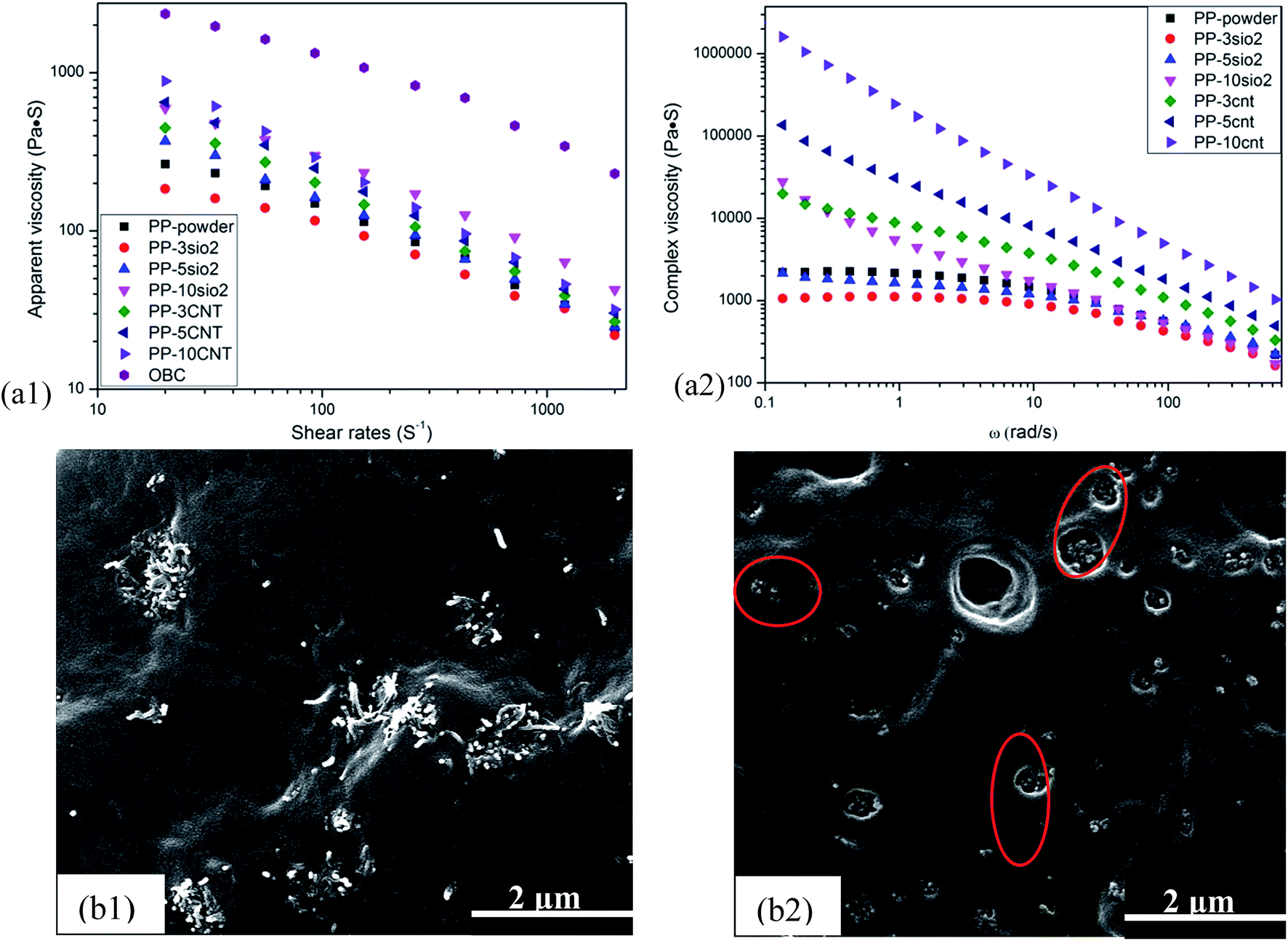
However, the morphological evolution of PP in the two-step strategy turns more complicated. According to the published literature, it has been confirmed that the effect of NP on the structure and properties of MFCs is quite complex. Especially when the composites are fabricated in two steps where NP is first compounded with the fibril-forming component, the viscoelastic response of the binary composites is dramatically different compared to the neat polymer and the microfibrils even fail to be formed at higher loadings.37 Therefore, it is necessary to figure out how the selective dispersion of SiO2 or CNTs affects the rheological properties. Fig. 7(a) shows the relationship between the apparent viscosity and the shear rate for neat OBC, neat PP, and PP/NP compounds at 180 °C. Over the whole shear rate range, the viscosity of PP/NP is higher than neat PP except for PP/3SiO2 display lower viscosity. The reduction of melt viscosity may be caused by slip between polymer matrix and filler.38,39 Generally, the deformation of dispersed melt drops depends mainly on the interfacial interaction, viscosity ratio and other mixing parameters. A lower viscosity ratio (ηd/ηm < 1) facilitate the fibrillation of the dispersed phase in a blend.17,23,37,40 Here, although the addition of NP could increase the melt viscosity of PP, the final viscosity of PP nanocomposites is still lower than neat OBC, implying ηd/ηm is smaller than 1. According to the mentioned theory, PP/NP hybrid melt is possible to deform into microfibrils. It should also be noted PP/CNTs compounds display higher viscosity than PP/SiO2, which can be clearly seen inthe dynamic rheometer test. That may be caused by the entanglement of CNTs fibers. At higher shear rate, the viscosity of PP/CNTs drops dramatically due to the de-bundled CNTs clusters. Whereas PP/SiO2 is less sensitive to an external shear field and the shear thinning effect takes place at larger shear rates compared to the PP/CNTs nanocomposites with the same filler loading. The different shear response of the two nanocomposites would also influence the deformation of PP/NP melt in the OBC matrix. When PP melt was hot stretched by the pinched roll, CNTs were prone to slip and align along the drawing direction. In other words, the incorporation of CNTs into PP did not hinder the melt deformation and the hybrid microfibrils of PP/CNTs were thus obtained. Whereas for SiO2-II, voids arose from poor adhesion between particle agglomerates and the PP matrix as indicated in Fig. 7(b).41–43 The defect would cause the delamination of the PP melt from the SiO2 agglomerates, leading to rough surface of PP fibrils. At 1 wt%, SiO2 would be easier to be agglomerated in some areas, where the defect could even result in the breakup of the PP melt. Therefore, some of the PP melt failed to form microfibrils with a large aspect ratio, instead only elongated ellipsoids or spheres were formed.
 |
| | Fig. 7 Rheological tested by Advanced Capillary Rheometer and strain-controlled dynamic rheometer respectively: (a1) apparent viscosity and (a2) complex viscosity of PP/NP; SEM photograph of (b1) PP/3CNTs and (b2) PP/3SiO2, the red circles indicate the voids between PP and SiO2. | |
3.3 Rheological behavior
Normally, the addition of fillers can alter the rheological properties of polymers significantly. Such effects are related to the filler's concentration, shape, deformability, level of dispersion, and the degree of interaction between the polymer and the fillers.44 Thus, the study of the viscoelastic behavior of polymer composites can provide some insight into their microstructures.
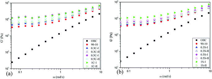
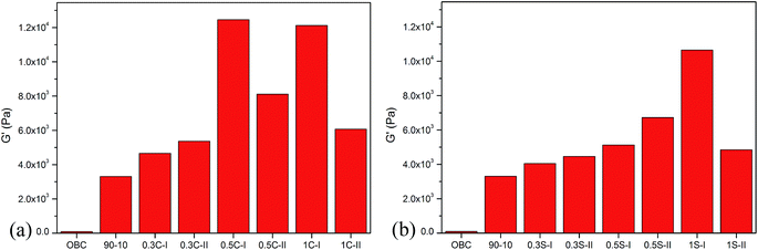
Fig. 8 displays the rheological responses of molten OBC and OBC/PP/SiO2 or CNTs compounds at 140 °C. The pure OBC had a classic viscoelastic response and at low frequencies, OBC's storage modulus (G′) was highly dependent on the frequency. The addition of 10 wt% in situ generated PP microfibrils increased the OBC melt's storage modulus by 3 orders of magnitude and a plateau region appeared at low frequencies. The weakened frequency-dependence indicates the transition in the melt's viscoelastic behavior from a liquid-like to a solid-like state.1 Such an increase in the melt's elastic behavior suggests the formation of a physically entangled network, which would have been created by the topological interactions of the PP microfibrils. The creation of such a network is a typical characteristic of the composites with deformable and long (that is, high aspect ratio) fibers.45 After adding NPs, MFCs displayed the similar G′ plot to OBC/PP MFCs (90-10). For better understanding of the influence of CNTs and SiO2 on the morphology, the storage modulus at a frequency ω = 0.0628 rad s−1 vs. nanofiller loadings is shown in Fig. 9. It is shown that the composites mixed by the one-step method displayed higher G′ for OBC/PP/CNTs. For 0.5C-I and 1C-I, the storage modulus is higher than 0.5C-II and 1C-II, respectively. In Fig. 6, we pointed out that plenty CNTs were dispersed around the PP fibrils. The CNTs with a large aspect ratio worked as bridges to connect the adjacent PP fibrils, making the physically entangled network more effective to restrict the chain mobility of OBC. Whereas for OBC/PP/SiO2, the smooth surface of SiO2 without surface modification failed to connect the PP fibrils at such lower loadings.46 Therefore, the SiO2-MFCs-I failed to show the synergetic enhancement as CNTs-MFCs-I did. For 1S-II, some of the PP/SiO2 hybrid melt failed to transform into microfibers and the physical network is jeopardized. Therefore, the G′ was even lower than 0.5S-II, indicating the rheological property was influenced by not only filler content, but also the fibrillar morphologies of PP.
 |
| | Fig. 8 Storage modulus (G′) of neat OBC and its MFCs without (90-10) and with nanoparticle filling: (a) OBC/PP/CNTs nanocomposites (b) OBC/PP/SiO2 nanocomposites. | |
 |
| | Fig. 9 Storage modulus (G′) as a function of nanofiller loading content and mixing strategies: (a) OBC/PP/CNTs nanocomposites (b) OBC/PP/SiO2 nanocomposites. | |
3.4 Mechanical properties
Fig. 10 shows the stress–strain curve of the MFCs and the tensile properties are concluded in Table 4. A remarkable climb in OBC's tensile strength was achieved by adding the in situ generated PP fibrils. The adding of CNTs contributes to the further mechanical enhancement. Clearly, when CNTs were mixed by two-step method, the as-formed hybrid microfibrils obtained further improved mechanical performance than pure PP fibrils. Therefore, the final mechanical properties of the nanocomposites were promoted. When CNTs were added by the one-step method, the CNTs dispersed in OBC matrix help PP fibrils to construct more improved networks as indicated by the rheological test. Synergetic enhancement of tensile properties was achieved from CNTs and PP fibrils.
 |
| | Fig. 10 Stress–strain curves of OBC/PP MFCs filled with nanoparticles: (a) OBC/PP/CNTs nanocomposites (b) OBC/PP/SiO2 nanocomposites. | |
Table 4 Mechanical properties of OBC and OBC/PP MFCs filled with nanoparticles. Note (a) the maximum tensile strain was controlled at 1000%
| Sample |
Tensile strength, MPa |
Elongation at break, % |
Sample |
Tensile strength, MPa |
Elongation at break, % |
| OBC |
3.8 ± 0.09 |
1000(a) |
|
|
|
| 90/10 |
4.7 ± 0.04 |
1000(a) |
|
|
|
| 0.3C-I |
6.1 ± 0.17 |
1000(a) |
0.3S-I |
5.8 ± 0.13 |
1000(a) |
| 0.3C-II |
7.3 ± 0.18 |
1000(a) |
0.3S-II |
5.7 ± 0.21 |
1000(a) |
| 0.5C-I |
7.8 ± 0.17 |
1000(a) |
0.5S-I |
6.1 ± 0.09 |
532.5 ± 37.81 |
| 0.5C-II |
8.2 ± 0.13 |
1000(a) |
0.5S-II |
7.3 ± 0.15 |
1000(a) |
| 1C-I |
8.1 ± 0.11 |
810.8 ± 26.34 |
1S-I |
5.9 ± 0.16 |
398.6 ± 43.15 |
| 1C-II |
8.3 ± 0.28 |
1000(a) |
1S-II |
6.2 ± 0.13 |
1000(a) |
When SiO2 was added by the two-step method with 0.3 and 1 wt%, the reinforcing effect is negligible due to the low silica loading and destructed PP fibrillar morphologies respectively. Only when the silica was loaded at 0.5 wt%, the balanced PP strength and its microfibrillar morphology resulted in the best mechanical performance. The flexibility of 0.5S-I and 1S-I dropped dramatically because the aggregation of silica particles and the poor de-wetting with the OBC matrix.
4. Conclusion
The nanoparticles (SiO2, CNTs) modified MFCs based on OBC/PP are fully investigated. Depending on the mixing process, the selective dispersions of nanoparticles in OBC and PP are obtained via a one- and two-step method, respectively. Influenced by the type of nanoparticles and filler content, the MFCs display differed microstructures and properties. When the nanoparticles are added by the one-step method, PP fibrils with a large aspect ratio could be obtained. Synergetic mechanical improvement is realized for CNTs because dispersed CNTs in the OBC matrix can work as bridges to connect the adjacent PP fibrils and form a more developed physical network. When the particles are added by the two-step method, CNTs could still lead to refined PP fibrils and further promote the mechanical performance of the MFCs. Whereas for SiO2, plenty bumps appeared in the PP fibrils and nodular-like PP, instead of large aspect ratio fibrils, were in situ generated. The synergetic reinforcing effect is negligible due to the coarse morphological structure.
Acknowledgements
This work was supported by the National Natural Science Foundation of China (grant no. 51421061).
References
- A. Rizvi, C. B. Park and B. D. Favis, Tuning viscoelastic and crystallization properties of polypropylene containing in situ generated high aspect ratio polyethylene terephthalate fibrils, Polymer, 2015, 68, 83–91 CrossRef CAS.
- N. K. Kim, S. Fakirov and D. Bhattacharyya, Polymer–Polymer and Single Polymer Composites Involving Nanofibrillar Poly(vinylidene Fluoride): Manufacturing and Mechanical Properties, J. Macromol. Sci., Part B: Phys., 2014, 53, 1168–1181 CrossRef CAS.
- S. Fakirov, D. Bhattacharyya and S. M. Panamoottil, Converting of Bulk Polymers Into Nanosized Materials With Controlled Nanomorphology, Int. J. Polym. Mater. Polym. Biomater., 2014, 63, 777–793 CrossRef CAS.
- R. McCardle, S. Fakirov and D. Bhattacharyya, Nanofibrillar Polymer-Polymer Composites: Effect of Reinforcement Orientation on the Mechanical Properties, Macromol. Symp., 2013, 327, 64–71 CrossRef CAS.
- V. Jašo, M. V. Rodić and Z. S. Petrović, Biocompatible fibers from thermoplastic polyurethane reinforced with polylactic acid microfibers, Eur. Polym. J., 2015, 63, 20–28 CrossRef.
- X.-C. Xia, Q.-P. Zhang, L. Wang, J.-M. Feng and M.-B. Yang, The Complex Crystalline Structure of Polyethylene/Polycarbonate Microfibril Blends in a Secondary Flow Field, Macromol. Chem. Phys., 2014, 215, 1146–1151 CrossRef CAS.
- N. Dencheva, Z. Denchev, N. Stribeck, M. Motovilin, A. Zeinolebadi, S. S. Funari and S. Botta, Nanostructure Transitions and Their Relation to Mechanical Properties in Polyethylene/Polyamide 6 Microfibrillar Composites as Revealed by SAXS/Straining Studies, Macromol. Mater. Eng., 2013, 298, 1100–1116 CAS.
- S. Naficy and H. Garmabi, Study of the effective parameters on mechanical and electrical properties of carbon black filled PP/PA6 microfibrillar composites, Compos. Sci. Technol., 2007, 67, 3233–3241 CrossRef CAS.
- D. Wang, G. Sun and B.-S. Chiou, A High-Throughput, Controllable, and Environmentally Benign Fabrication Process of Thermoplastic Nanofibers, Macromol. Mater. Eng., 2007, 292, 407–414 CrossRef CAS.
- Y. Mei, Y. Huang, Y. He and Q. Yang, Development of fibrillar morphology in immiscible PP/PS blends under shear flow, J. Appl. Polym. Sci., 2012, 124, 4838–4846 CrossRef CAS.
- Y. Lei, Q. Wu and Q. Zhang, Morphology and properties of microfibrillar composites based on recycled poly(ethylene terephthalate) and high density polyethylene, Composites, Part A, 2009, 40, 904–912 CrossRef.
- N. Ning, S. Fu, W. Zhang, F. Chen, K. Wang, H. Deng, Q. Zhang and Q. Fu, Realizing the enhancement of interfacial interaction in semicrystalline polymer/filler composites via interfacial crystallization, Prog. Polym. Sci., 2012, 37, 1425–1455 CrossRef CAS.
- Z. Li, Y. Shi, H. Liu, F. Chen, Q. Zhang, K. Wang and Q. Fu, Effect of melting temperature on interfacial interaction and mechanical properties of polypropylene (PP) fiber reinforced olefin block copolymers (OBCs), RSC Adv., 2014, 4, 45234–45243 RSC.
- S. Zhao, L. Cheng, Y. Guo, Y. Zheng and B. Li, PA6 and Kevlar fiber reinforced isotactic polypropylene: structure, mechanical properties and crystallization and melting behavior, Mater. Des., 2012, 35, 749–753 CrossRef CAS.
- J. Gao, Y. Dai, X. Wang, J. Huang, J. Yao, J. Yang and X. Liu, Effects of different fluorination routes on aramid fiber surface structures and interlaminar shear strength of its composites, Appl. Surf. Sci., 2013, 270, 627–633 CrossRef CAS.
- J. Chen, P. Chen, L. Wu, J. Zhang and J. He, Fibrillation of liquid crystalline polymer in polysulfone promoted by increased system elasticity via adding nano-silica, Polymer, 2007, 48, 4242–4251 CrossRef CAS.
- Y. Mei, Y. Huang, Q. Yang and G. Li, Improved shape stability of nanosilica-filled PBT fibrils in PS matrix: effects of accelerated crystallization and enhanced viscoelasticity, Polymer, 2012, 53, 5413–5422 CrossRef CAS.
- Y. Liu, Z. Zhao, D. Tang, M. Kong, Q. Yang, Y. Huang, X. Liao and Y. Niu, Effect of nanoparticles on the morphology and properties of PET/PP in situ microfibrillar reinforced composites, Polym. Compos. DOI:10.1002/pc.23869.
- L. Huang, Mechanical Properties and Crystallization Behavior of Polypropylene/Nano-SiO2 Composites, J. Reinf. Plast. Compos., 2006, 25, 1001–1012 CrossRef CAS.
- J.-F. Gao, D.-X. Yan, B. Yuan, H.-D. Huang and Z.-M. Li, Large-scale fabrication and electrical properties of an anisotropic conductive polymer composite utilizing preferable location of carbon nanotubes in a polymer blend, Compos. Sci. Technol., 2010, 70, 1973–1979 CrossRef CAS.
- S.-N. Li, B. Li, Z.-M. Li, Q. Fu and K.-Z. Shen, Morphological manipulation of carbon nanotube/polycarbonate/polyethylene composites by dynamic injection packing molding, Polymer, 2006, 47, 4497–4500 CrossRef CAS.
- S. Yesil, O. Koysuren and G. Bayram, Effect of microfiber reinforcement on the morphology, electrical, and mechanical properties of the polyethylene/poly(ethylene terephthalate)/carbon nanotube composites, Polym. Eng. Sci., 2010, 50, 2093–2105 CAS.
- Z. Li, C. Sun, X. Li, Q. Zhang and Q. Fu, In situ formation of polypropylene (PP) fibrils in the olefinic block copolymer (OBC): effect of viscosity ratio and OBC block architecture, RSC Adv., 2015, 5, 85442–85445 RSC.
- Z. Li, Y.-J. Shi, C.-X. Sun, Q. Zhang and Q. Fu, In situ micro and nano fibrillar reinforced elastomer composites based on polypropylene (PP)/olefinic block copolymer (OBC), Compos. Sci. Technol., 2015, 115, 34–42 CrossRef CAS.
- F. Fenouillot, P. Cassagnau and J. C. Majesté, Uneven distribution of nanoparticles in immiscible fluids: morphology development in polymer blends, Polymer, 2009, 50, 1333–1350 CrossRef CAS.
- M. Ji, H. Deng, D. Yan, X. Li, L. Duan and Q. Fu, Selective localization of multi-walled carbon nanotubes in thermoplastic elastomer blends: An effective method for tunable resistivity–strain sensing behavior, Compos. Sci. Technol., 2014, 92, 16–26 CrossRef CAS.
- L. Elias, F. Fenouillot, J. C. Majeste and P. Cassagnau, Morphology and rheology of immiscible polymer blends filled with silica nanoparticles, Polymer, 2007, 48, 6029–6040 CrossRef CAS.
- E. A. Guggenheim, The Principle of Corresponding States, J. Chem. Phys., 1945, 13, 253 CrossRef CAS.
- S. Thankappan Nair, P. P. Vijayan, P. Xavier, S. Bose, S. C. George and S. Thomas, Selective localisation of multi walled carbon nanotubes in polypropylene/natural rubber blends to reduce the percolation threshold, Compos. Sci. Technol., 2015, 116, 9–17 CrossRef CAS.
- S. Bagheri-Kazemabad, D. Fox, Y. Chen, L. M. Geever, A. Khavandi, R. Bagheri, C. L. Higginbotham, H. Zhang and B. Chen, Morphology, rheology and mechanical properties of polypropylene/ethylene–octene copolymer/clay nanocomposites: effects of the compatibilizer, Compos. Sci. Technol., 2012, 72, 1697–1704 CrossRef CAS.
- X.-Q. Liu, Y. Wang, W. Yang, Z.-Y. Liu, Y. Luo, B.-H. Xie and M.-B. Yang, Control of morphology and properties by the selective distribution of nano-silica particles with different surface characteristics in PA6/ABS blends, J. Mater. Sci., 2012, 47, 4620–4631 CrossRef CAS.
- P. K. S. Mural, G. Madras and S. Bose, Positive temperature coefficient and structural relaxations in selectively localized MWNTs in PE/PEO blends, RSC Adv., 2014, 4, 4943 RSC.
- L. Lu, Z. Zhou, Y. Zhang, S. Wang and Y. Zhang, Reinforcement of styrene–butadiene–styrene tri-block copolymer by multi-walled carbon nanotubes via melt mixing, Carbon, 2007, 45, 2621–2627 CrossRef CAS.
- V. C. Sara Filippi, G. Polacco, M. Paci, L. I. Minkova and P. Magagnini, Reactive compatibilizer precursors for LDPE PA6 blends, 1. Ethylene acrylic acid copolymers, Macromol. Chem. Phys., 2002, 203, 1512–1525 CrossRef.
- I. Kelnar, L. Kaprálková, J. Kratochvíl, Z. Padovec, M. Růžička and J. Hromádková, Effect of layered silicates and reactive compatibilization on structure and properties of melt-drawn HDPE/PA6 microfibrillar composites, Polym. Bull., 2016, 73, 1673–1688 CrossRef CAS.
- K. Wang, C. Wang, J. Li, J. Su, Q. Zhang, R. Du and Q. Fu, Effects of clay on phase morphology and mechanical properties in polyamide 6/EPDM-g-MA/organoclay ternary nanocomposites, Polymer, 2007, 48, 2144–2154 CrossRef CAS.
- X.-B. Xu, Z.-M. Li, R.-Z. Yu, A. Lu, M.-B. Yang and R. Huang, Formation of in situ CB/PET Microfibers in CB/PET/PE Composites by Slit Die Extrusion and Hot Stretching, Macromol. Mater. Eng., 2004, 289, 568–575 CrossRef CAS.
- D. Kim, S. Srivastava, S. Narayanan and L. A. Archer, Polymer nanocomposites: polymer and particle dynamics, Soft Matter, 2012, 8, 10813 RSC.
- J. W. Cho and D. R. Paul, Nylon 6 nanocomposites by melt compounding, Polymer, 2001, 42, 1083–1094 CrossRef CAS.
- K. Dai, X.-B. Xu and Z.-M. Li, Electrically conductive carbon black (CB) filled in situ microfibrillar poly(ethylene terephthalate) (PET)/polyethylene (PE) composite with a selective CB distribution, Polymer, 2007, 48, 849–859 CrossRef CAS.
- M. Gómez, D. Bracho, H. Palza and R. Quijada, Effect of morphology on the permeability, mechanical and thermal properties of polypropylene/SiO2 nanocomposites, Polym. Int., 2015, 64(9), 1245–1251 CrossRef.
- F. Dorosti, M. R. Omidkhah, M. Z. Pedram and F. Moghadam, Fabrication and characterization of polysulfone/polyimide–zeolite mixed matrix membrane for gas separation, Chem. Eng. J., 2011, 171, 1469–1476 CrossRef CAS.
- W. Li, A. K. Schlarb and M. Evstatiev, Study of PET/PP/TiO2 microfibrillar-structured composites, part 1: preparation, morphology, and dynamic mechanical analysis of fibrillized blends, J. Appl. Polym. Sci., 2009, 113, 1471–1479 CrossRef CAS.
- Y. Li, M. Kröger and W. K. Liu, Nanoparticle Geometrical Effect on Structure, Dynamics and Anisotropic Viscosity of Polyethylene Nanocomposites, Macromolecules, 2012, 45, 2099–2112 CrossRef CAS.
- A. R. Kakroodi, Y. Kazemi, W. Ding, A. Ameli and C. B. Park, Poly(lactic acid)-Based In Situ Microfibrillar Composites with Enhanced Crystallization Kinetics, Mechanical Properties, Rheological Behavior, and Foaming Ability, Biomacromolecules, 2015, 16, 3925–3935 CrossRef CAS PubMed.
- G. Hatui, S. Sahoo, C. Kumar Das, A. K. Saxena, T. Basu and C. Y. Yue, Effect of nanosilica and polyphosphazene elastomer on the in situ fibrillation of liquid crystalline polymer (LCP) and thermo-mechanical properties of polybutylene terephthalate (PBT)/LCP blend system, Mater. Des., 2012, 42, 184–191 CrossRef CAS.
|
| This journal is © The Royal Society of Chemistry 2016 |
Click here to see how this site uses Cookies. View our privacy policy here.