
Colorimetric sensing of melamine using colloidal magnetically assembled molecularly imprinted photonic crystals
Aimei You,
Yuhua Cao* and
Guangqun Cao
The Key Laboratory of Food Colloids and Biotechnology, Ministry of Education, School of Chemical and Material Engineering, Jiangnan University, Wuxi 214122, P. R. China. E-mail: yuhuacao64@gmail.com
First published on 29th August 2016
Abstract
A visually perceptible, highly selective and structurally simple colorimetric sensor for melamine (MEL) based on colloidal magnetically assembled molecularly imprinted photonic crystals (MIPCs) has been constructed. The color of the MIPCs red-shifted significantly as the MEL concentration increased. The largest redshift could reach 200 nm, and the detection limit for MEL was 10−5 mg mL−1.
Photonic crystals, a kind of innovative material with a periodic dielectric structure has become a focus of intensive research due to the capability to control and manipulate the propagation of light.1,2 The photonic crystal technique has been applied in numerous promising fields, including displays, sensors, and anti-counterfeiting.3–7 The unique structural color of photonic crystals could be derived from the periodic arrangement of regularly shaped materials, including spheres or a multiplicity of layers with different dielectric constants.8 The specific color or the diffraction wavelength is mainly governed by the distance between the spheres or the layers, according to the Bragg's law λ = 2nd
![[thin space (1/6-em)]](https://www.rsc.org/images/entities/char_2009.gif) sinθ (λ is the diffraction wavelength, n is the mean refractive index of the solution, d is the lattice plane spacing and θ = 90° is the angle of the incident light).9 Therefore, the diffraction wavelength could shift following the change of the crystal periodicity, which offers a convenient and effective tool for the design of stimuli responsive materials. In addition, photonic crystals could directly transform the sensing effects into visual discernable signals. However, as a stimuli responsive material, especially for chemical and biological sensing, the specificity or selectivity is vital. Asher et al.10–12 pioneered several photonic crystal hydrogel films to sense the substances by attaching the molecular recognition agents to the photonic crystal hydrogels.
sinθ (λ is the diffraction wavelength, n is the mean refractive index of the solution, d is the lattice plane spacing and θ = 90° is the angle of the incident light).9 Therefore, the diffraction wavelength could shift following the change of the crystal periodicity, which offers a convenient and effective tool for the design of stimuli responsive materials. In addition, photonic crystals could directly transform the sensing effects into visual discernable signals. However, as a stimuli responsive material, especially for chemical and biological sensing, the specificity or selectivity is vital. Asher et al.10–12 pioneered several photonic crystal hydrogel films to sense the substances by attaching the molecular recognition agents to the photonic crystal hydrogels.
Molecular imprinting is a prospective technique to create artificial receptors with specific molecular recognition sites.13 Owing to the unique selective affinity and the structural predictability, molecularly imprinted polymers have been widely applied in various fields, such as chromatographic separation, solid-phase extraction and biosensors.14–17 Molecularly imprinted photonic crystals (MIPCs) combining the unique optical property of photonic crystals with the specific recognition properties of molecularly imprinted polymers, have attracted considerable attentions.18–22 Li et al.23 adopted colloidal silica crystal as a template and molecular imprinting technique in the process of the hydrogel formation to prepare imprinted photonic polymers for chiral recognition. Huang et al.24 fabricated a novel opal closest-packing photonic crystal for the detection of trace 17β-estradiol by fixing the imprinted colloidal spheres in a polyacrylamide hydrogel matrix. Gao et al.25 fabricated a new opal photonic crystal sensor to detect bisphenol A by vertical deposition of the monodisperse imprinted spheres into a polymerized crystalline colloidal array. However, the formation of high quality colloidal crystal array by these traditional methods is a time-consuming process, and the etching of the photonic crystal template also takes days to weeks. Whereas, the hydrogel matrix might have a response to some special functional groups, which causes a blurry response phenomenon.
In the present work, we constructed a novel colloidal colorimetric sensor for melamine (MEL) based on magnetically assembled molecularly imprinted photonic crystals (MIPCs). The construction of the MIPCs sensor could be summarized as the four parts: the preparation of MMIPs, the elution of the template molecules, the magnetic assembly of the photonic crystal structure and the MEL response. The colloidal magnetically assembled MIPCs sensor could directly transmit the stimuli from the adsorption of MEL into the optical signals. The diffraction colors of the colorimetric sensor red-shifted from very light purple to orange as increasing MEL concentration from 10−5 mg mL−1 to 10−2 mg mL−1. A standard color card was used to assist in judging MEL concentration semi-quantitatively and reducing the personal error in the visual detection process.
The procedures to construct the MIPCs sensor was illustrated in Fig. 1A. MEL MMIPs were prepared by miniemulsion polymerization. Firstly, three-step miniemulsification was carried out to obtain the magnetite miniemulsion A, the polymeric precursors and MEL miniemulsion B, and the mixed miniemulsion of miniemulsion A with miniemulsion B. Then, the initiator potassium peroxydisulfate (KPS) was added to conduct the polymerization reaction. After that, MMIPs with the specific binding nanocavities were obtained after the removal of MEL template molecules with the eluents. Finally, MIPCs sensor was constructed in a magnetic field by dispersing MMIPs in MEL solutions. The MIPCs sensor has the advantages such as simple structure, convenient operation and sensitive response. In addition, the colorimetric sensing test for MEL did not need expensive or sophisticated instruments, only a magnet was required to implement colorimetric sensing. It has great potential in-field fast and for real-time on-line analysis.
 | ||
| Fig. 1 (A) Schematic illustration of preparation of the MIPCs and the interaction of (B) AM and (C) MAA with MEL. | ||
AM and MAA were chosen as the functional monomers, owing to the strong hydrogen bond interactions between them and MEL, as shown in Fig. 1B and C, respectively. The complex of AM and MAA with MEL was cross-linked with EGDMA to form the specific binding nanocavities. After the elution of the template molecules, cavities as specific binding sites for MEL were formed in the polymer shell. MMIPs obtained by three steps miniemulsion polymerization were with perfect sphere morphology, observed by transmission electron microscope (TEM) and scanning electron microscope (SEM), as shown in Fig. 2. From Fig. 2A, it could be seen clearly that superparamagnetic OA–Fe3O4 nanoparticles were encapsulated homogenously by the imprinted polymer layer to form a distinct core–shell structure. The mean size of the MMIPs was 97 nm and the thickness of the imprinted polymer shell was 11.3 nm. Fig. 2B was the SEM images of MMIPs, in which the sample was prepared by drying a drop of MMIPs colloids on the copper network under a magnetic field. Although the nanoparticles were closely together owing to the drying process, the photonic crystal chain-like structures could be seen clearly. The hydrodynamic size of MMIPs was 208.2 nm, with a polydispersity of 0.184. The MMIPs could be directly dispersed in MEL aqueous solution and then magnetically assembled into colloidal MIPCs sensor, with the assistance of a magnetic field. When a magnetic field was applied, two types of magnetic forces would be exerted on MMIPs, the magnetic dipole–dipole force and the magnetic packing force. The magnetic forces trended to attract the MMIPs, while the electrostatic repulsive interactions from the negatively charged imprinted polymer shell kept the MMIPs far away from each other. Therefore, the successful construction of the photonic crystal structure was attributed to the balance between the magnetic attraction and the electrostatic repulsion. To the best of our knowledge, it is the first work to prepare colloidal magnetically assembled MIPCs for sensing MEL. In comparison with the hydrogel matrix, colloidal magnetically assembled MIPCs have much remarkable improvements. Firstly, the template molecules were directly imprinted on the photonic crystal assembly blocks rather than on the hydrogel matrix. Secondly, the experimental process was simplified by omitting the commonly used hydrogels polymerization step. Thirdly, the assembly of the photonic crystal was simple, rapid, green and switchable by utilizing a magnetic field.
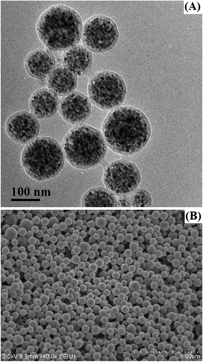 | ||
| Fig. 2 (A) TEM and (B) SEM images of MMIPs. | ||
As a sensor, the recognition element and an appropriate transduction element are all necessarily required.26 MIPCs, integrating the specific recognition element of molecularly imprinted polymers with the unique optical property of photonic crystals, could directly transfer the molecular recognition process into readable optical signals. The sensing response of MIPCs to MEL was examined with a series of concentrations of MEL in aqueous solutions (10−5 mg mL−1, 10−4 mg mL−1, 10−3 mg mL−1, 10−2 mg mL−1), as well as a blank solution as the control. As shown in Fig. 3A–E, MIPCs sensor exhibited a visual readable color change. In the blank solution without MEL, MIPCs showed a very light purple color, and the diffraction light was very weak. The optical phenomena concorded with the reflection spectrum curve A in Fig. 3F. With increasing the MEL concentration from 10−5 mg mL−1 to 10−2 mg mL−1, the color of MIPCs changed to green, yellow and orange, respectively. In Fig. 3F, the corresponding Bragg diffraction wavelength shifted from 420 nm (0 mg mL−1) to 620 nm (10−2 mg mL−1). The largest redshift could reach 200 nm which can be clearly recognized by the naked eye. It was also found that MIPCs were very sensitive to the rebinding of the MEL molecules. A clear redshift of the Bragg diffraction was detectable, and the response time was less than 5 minutes. The detection limit of the colorimetric sensor for MEL was down to 10−5 mg mL−1, it indicated that the colorimetric sensor had great potential in the qualitative or semiquantitative rapid detection. The colorimetric sensing results could also be estimated using a standard color card (Fig. 3G) to assist in judging the concentration range of MEL semiquantitatively and reducing the personal error in the visual detection.
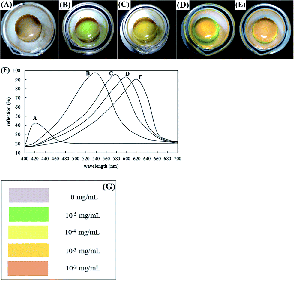 | ||
| Fig. 3 Response behavior of MIPCs to a series of concentrations of MEL solutions characterized by photograph (A–E), (F) reflection spectra and (G) standard color card to show the relationship between MEL concentration and the corresponding color. | ||
In order to demonstrate the direct correlation between the diffraction wavelength shift and the rebinding of MEL in the imprinted binding sites, we also performed control experiments by investigating the response of superparamagnetic non-imprinted nanoparticles (MNIPs) or MMIPs without removal template molecules to a series of concentrations of MEL solutions. As expected, the redshift of the Bragg diffraction was not detected in those above mentioned contrast groups. Simultaneously, the selectivity of the MIPCs sensor was studied by choosing cyanuric acid and atrazine as the reference compounds because they were structurally analogous to MEL. The optical response of the MIPCs sensor to these reference compounds solutions with the concentrations from 10−5 mg mL−1 to 10−2 mg mL−1 were investigated. The diffraction colors of MIPCs in response to cyanuric acid and atrazine were light yellow (in Fig. 4A) and light yellow-green (in Fig. 4B), respectively. Compared with the diffraction color in the blank solution in Fig. 3A, there were slight redshifts of the diffraction colors both in Fig. 4A and B. The slight redshifts induced by the reference compounds might be attributed to the nonspecific adsorption. However, none of the redshift phenomena occurred as increasing the concentration of the reference compounds from 10−5 mg mL−1 to 10−2 mg mL−1. The results described above clearly indicated that the colorimetric MIPCs sensor has high selectivity for MEL.
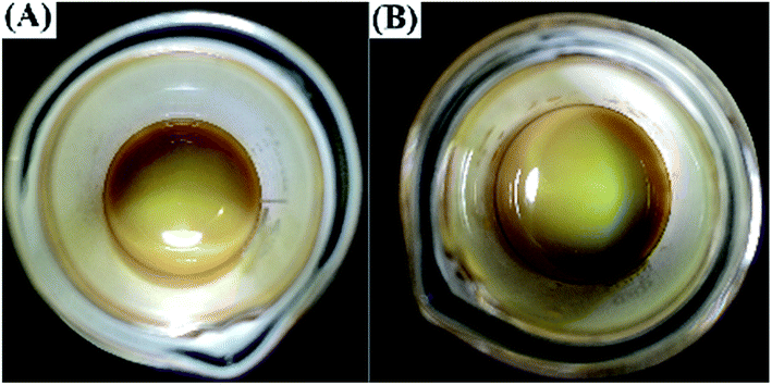 | ||
| Fig. 4 Optical response of MIPCs to (A) cyanuric acid and (B) atrazine (10−2 mg mL−1 for each). | ||
With the assistance of an external magnetic field, MMIPs suspension was assembled into photonic crystal structure, which had a periodic photon forbidden band and led to the optical diffraction. The resulting optical behavior followed the Bragg's law λ = 2ndsinθ. Therefore, the redshift of the Bragg diffraction wavelength should be mainly attributed to the change of the lattice plane spacing d. When MMIPs were dispersed in MEL solutions, rebinding process of MEL molecules to MMIPs could occur. Fig. 5 displayed the zeta potential of MMIPs suspension in a series of concentrations of MEL aqueous solutions. As increasing MEL concentration from 0 mg mL−1 to 10−1 mg mL−1, the negative zeta potential increased from −17.14 mV to −35.27 mV. As a consequence, the electrostatic repulsion between MMIPs got stronger and pushed the nanoparticles far away from each other. Therefore, the lattice plane spacing d became bigger, as a result, the redshift of the Bragg diffraction wavelength of the MIPCs sensor was observed. It was worth mentioning, the redshift mechanism based on the electrostatic repulsion was different from the traditionally reported hydrogel sensor depending on the swelling or shrinking of the gel volume.
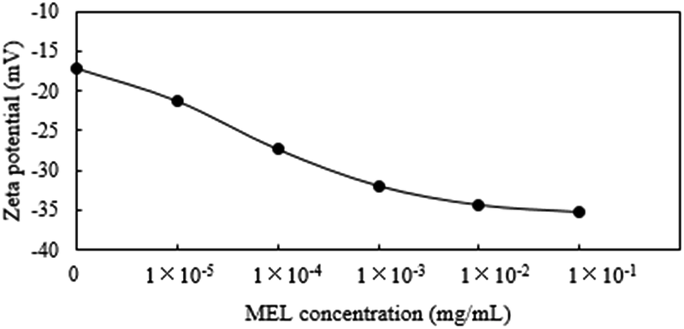 | ||
| Fig. 5 The zeta potential of MMIPs in a series of concentrations of MEL solutions. | ||
In conclusion, based on colloidal magnetically assembled MIPCs, we have constructed a visually perceptible, highly selective and structurally simple colorimetric sensor with response to MEL for the first time. The colloidal MIPCs sensor could directly transform the MEL recognition events into optical signals and realize naked eye visible qualitative or semiquantitative detection of MEL molecule with detection limit of 10−5 mg mL−1. Further research should be focused on the improvement of the selectivity and stability to facilitate its application in real sample analysis.
Experimental section
Preparation of colloidal magnetically assembled MIPCs
Oleic acid (OA) modified superparamagnetic Fe3O4 nanoparticles (OA–Fe3O4) were synthesized by the co-precipitation method.27 MEL MMIPs were prepared by miniemulsion polymerization, and the experimental procedure was proceeded as described in the preliminary work of our group.28 The reagents dosages were as follows: OA–Fe3O4 0.5 g, organic solvent chloroform 2.5 mL, MEL 1 mmol, sodium dodecyl sulphate (SDS) 2.5 mmol L−1 (80 mL), methyl methacrylate (MMA) 1 mmol, methacrylic acid (MAA) 0.2 mmol, acrylamide (AM) 6 mmol and ethyleneglycol dimethacrylate (EGDMA) 6 mmol. In step (2) chloroform and cetyl alcohol were omitted due to the solubility of MEL and the co-stability of OA. The template molecules were removed from MMIPs (0.3 g) by washing with 0.1 mol L−1 hydrochloric acid (10 mL, one time) firstly and then methyl alcohol (30 mL each time, 4 times). The MNIPs were prepared with the same procedure without MEL.Reflection measurements of MIPCs in response to MEL
MMIPs (10 mg) were dispersed in 2 mL aqueous solution containing a series of concentrations of MEL, respectively. Then the colloidal suspension was magnetically assembled into photonic crystal structure with the assistance of an external magnetic field (0.2 T). All reflection spectrum measurements were recorded with a miniature fiber optic spectrometer (FLA 5000+, China). Typically, the reflection probe was placed perpendicular to the MIPCs samples vial, and the NdFeB magnet was placed in the direction opposite to the reflection probe (beneath the sample container). The corresponding color changes were photographed using a common digital camera (Canon, EOS KissX4) under a daylight lamp.Characterization
The morphology and size of the MMIPs were characterized with transmission electron microscope (TEM, JEOL JEM-2100) and scanning electron microscope (SEM, Hitachi S-4800). The hydrodynamic size, polydispersity and zeta potential of MMIPs were measured by zeta potential and nanometer particle analyzer (ZetaPALS, Brookhaven Instruments Corporation, USA).Acknowledgements
We gratefully acknowledge the financial supports from the National Natural Science Foundation of China (grant No. 21405133, 21774056) and MOE & SAFEA for the 111 Project (B13025).Notes and references
- S. John, Phys. Rev. Lett., 1987, 58, 2486 CrossRef CAS PubMed.
- E. Yablonovitch, Phys. Rev. Lett., 1987, 58, 2059 CrossRef CAS PubMed.
- Z. Liu, Q. Zhang, H. Wang and Y. Li, Chem. Commun., 2011, 47, 12801 RSC.
- L. Bai, Z. Y. Xie, W. Wang, C. W. Yuan, Y. J. Zhao, Z. D. Mu, Q. F. Zhong and Z. Z. Gu, ACS Nano, 2014, 8, 11094 CrossRef CAS PubMed.
- K. I. MacConaghy, C. I. Geary, J. L. Kaar and M. P. Stoykovich, J. Am. Chem. Soc., 2014, 136, 6896 CrossRef CAS PubMed.
- H. S. Lee, T. S. Shim, H. Hwang, S. M. Yang and S. H. Kim, Chem. Mater., 2013, 25, 2684 CrossRef CAS.
- J. Y. Shieh, J. Y. Kuo, H. P. Weng and H. H. Yu, Langmuir, 2013, 29, 667 CrossRef CAS PubMed.
- C. Fenzl, T. Hirsch and O. S. Wolfbeis, Angew. Chem., 2014, 53, 3318 CrossRef CAS PubMed.
- X. L. Xu, G. Friedman, K. D. Humfeld, S. A. Majetich and S. A. Asher, Chem. Mater., 2002, 14, 1249 CrossRef CAS.
- M. B. Moshe, V. L. Alexeev and S. S. Asher, Anal. Chem., 2006, 78, 5149 CrossRef PubMed.
- S. A. Asher, A. C. Sharma, A. V. Goponenko and M. M. Ward, Anal. Chem., 2003, 75, 1676 CrossRef CAS PubMed.
- J. T. Zhang, Z. Cai, D. H. Kwak, X. Liu and S. A. Asher, Anal. Chem., 2014, 86, 9036 CrossRef CAS PubMed.
- L. Chen, S. Xu and J. Li, Chem. Soc. Rev., 2011, 40, 2922 RSC.
- J. Tan, Z. T. Jiang, R. Li and X. P. Yan, TrAC, Trends Anal. Chem., 2012, 39, 207 CrossRef CAS.
- W. Cheng, H. Ma, L. Zhang and Y. Wang, Talanta, 2014, 120, 255 CrossRef CAS PubMed.
- L. Zhu, Y. Cao and G. Cao, Biosens. Bioelectron., 2014, 54, 258 CrossRef CAS PubMed.
- P. S. Sharma, F. D. Souza and W. Kutner, TrAC, Trends Anal. Chem., 2012, 34, 59 CrossRef CAS.
- Z. Yang, D. Shi, M. Chen and S. Liu, Anal. Methods, 2015, 7, 8352 RSC.
- F. Liu, S. Huang, F. Xue, Y. Wang, Z. Meng and M. Xue, Biosens. Bioelectron., 2012, 32, 273 CrossRef CAS PubMed.
- Z. Wu, C. A. Tao, C. Lin, D. Shen and G. Li, Chemistry, 2008, 14, 11358 CrossRef CAS PubMed.
- Y. Zhang, Z. Pan, Y. Yuan, Z. Sun, J. Ma, G. Huang, F. Xing and J. Gao, PCCP Phys. Chem. Chem. Phys., 2013, 15, 17250 RSC.
- X. Wang, Z. Mu, R. Liu, Y. Pu and L. Yin, Food Chem., 2013, 141, 3947 CrossRef CAS PubMed.
- X. Hu, Q. An, G. Li, S. Tao and J. Liu, Angew. Chem., 2006, 45, 8145 CrossRef CAS PubMed.
- N. Sai, Y. Wu, Z. Sun, G. Huang and Z. Gao, Talanta, 2015, 144, 157 CrossRef CAS PubMed.
- C. Guo, C. Zhou, N. Sai, B. Ning, M. Liu, H. Chen and Z. Gao, Sens. Actuators, B, 2012, 166–167, 17 CrossRef CAS.
- F. Xue, Y. F. Wang, Q. H. Wang, Z. H. Meng, M. Xue, S. Y. Huang and W. Lu, Chin. J. Anal. Chem., 2012, 40, 218 CAS.
- A. You, Y. Cao and G. Cao, RSC Adv., 2015, 5, 93945 RSC.
- L. Zhu, X. Yang and Y. Cao, Anal. Lett., 2013, 46, 982 CrossRef CAS.
| This journal is © The Royal Society of Chemistry 2016 |