Thiamine hydrochloride (vitamin B1) as modifier agent for TiO2 nanoparticles and the optical, mechanical, and thermal properties of poly(vinyl chloride) composite films
Shadpour Mallakpour*abc and
Marzieh Adnany Sadatya
aOrganic Polymer Chemistry Research Laboratory, Department of Chemistry, Isfahan University of Technology, Isfahan, 84156-83111, Islamic Republic of Iran. E-mail: mallak@cc.iut.ac.ir; mallak777@yahoo.com; mallakpour84@alumni.ufl.edu; Fax: +98-31-3391-2350; Tel: +98-31-3391-3267
bNanotechnology and Advanced Materials Institute, Isfahan University of Technology, Isfahan, 84156-83111, Islamic Republic of Iran
cCenter of Excellence in Sensors and Green Chemistry, Department of Chemistry, Isfahan University of Technology, Isfahan, 84156-83111, Islamic Republic of Iran
First published on 20th September 2016
Abstract
In the present investigation, TiO2 nanoparticles (NPs) were used for improving the thermal, mechanical and optical properties of poly(vinyl chloride) (PVC) matrix. To prevent the aggregation of TiO2 NPs, surface modification of TiO2 NPs was performed using vitamin B1 as a natural organic molecule with environmentally friendly and inexpensive properties. PVC nanocomposite (NC) films were prepared with different contents of TiO2 NPs via ultrasonic irradiation as a fast method and then the NCs were investigated using various techniques. Transmission electron microscopy images of NC films showed that TiO2 NPs were uniformly placed into the polymer matrix. Thermogravimetric analysis results showed enhancement in thermal stability of all NCs. From mechanical tests it was found that increasing the elongation at break and reducing the Young's modulus lead to increasing toughness of NC films. Water contact angle results indicated that the hydrophobicity of NCs were enhanced with increasing the concentration of TiO2 NPs.
1. Introduction
Polymer nanocomposites are often defined as the combination of a polymer matrix and additives that have at least one dimension in the nanometer range. The additives can be one-dimensional (examples include nanotubes), two-dimensional (examples contain clay), or three-dimensional (including spherical particles). Over the past decade, polymer NCs have attracted significant attention in both academia and industry, due to their excellent mechanical properties such as elastic stiffness and strength with only a small amount of the nanoadditives. Other preferable properties of polymer NCs include barrier resistance, flame retardancy, scratch/wear resistance, optical, magnetic and electrical properties.1 Polymer/inorganic NCs due to the large interfacial areas and the strong interfacial interactions have become a significant branch of materials science, chemistry, physics and biology, among other fields, because they often lead to enhanced properties and even new functions compared with the corresponding compounds.2 The homogeneous dispersion of inorganic NPs into the organic matrix leads to enhanced mechanical, thermal, and gas barrier properties of NCs at low inorganic content.3 Therefore, polymer/inorganic NCs provide a promising way to successfully combine the advantages of organic and inorganic materials.4Poly(vinyl chloride) (PVC) is one of the most versatile polymers after polyethylene and polypropylene. In addition, it can easily be modified,5 excellent corrosion resistance, good flame retardancy,6 chemically stable, biocompatible, and inexpensive.7,8 One of the major problems that limit the practical use of this polymer is its lower thermal stability and brittle properties.7–9 PVC is unstable when exposed to high temperatures during its application.5 To improve these limitations and achieve desired properties, nano-fillers must be distributed uniformly in polymer matrix.9 PVC due to good balance price/performance has been allowed to penetrate many applications such as clothing, furniture,9 construction, electronics, automobile industry,10 pipes, cable insulation and packaging foils.11 PVC has been extensively used for the fabrication of biomedical devices and employed in applications including urinary catheters, blood storage bags, and blood tubing in extracorporeal circuits.12
Utilizing metal nanoparticles (NPs) into polymeric matrices has been studied extensively to improve features and capacities such as mechanical, electrical, thermal and optical properties.13 For example, PVC/TiO2 NCs were prepared by Mallakpour and et al. that found the presence of TiO2 NPs can improve thermal, mechanical and optical properties of PVC.14 In another article, PVC/ZrO2 NCs were prepared that showed more flexibility and thermal stability than pure PVC.15 Also, they prepared PVC NCs filled with modified SiO2 NPs which showed more thermal stability and optical absorption than pure PVC.16
Such inorganic/organic system can be applicable in many fields, in particular in drug delivery, separation and purification of chemicals, development of shape-memory materials and in catalysis.17
Among the metal NPs, TiO2 particles have attracted much attention due to their good photostability, nontoxicity, chemical and biological ineffective, antibacterial properties, UV-resistance and low cost.18,19 TiO2 NPs have been used for various applications including photocatalysis, catalytic supports, polymeric NCs, solar cells, sensors, transducer, and hydrogen generation etc.20–22 Due to its compatibility with the environment, more researches are devoted to applications in implantation and drug delivery.20 TiO2 NPs can be straightly added to organic coating, but due to the high surface area and high polarity, there is a strong tendency to aggregate.23 Aggregation occurs when particles are combined loosely. The aggregation prevents the obtaining of improved properties and the achieving of various applications by nanostructured materials. The strategies for avoiding aggregation are mainly attributed to particle coating by a capping agent, application of coupling agent and charging the filler surface to separate them via electrostatic revulsions. Also, using optimal parameters in the production process can lead to an efficient separation of aggregates.24
Different organic or inorganic materials can be used as modifiers to surface modification of NPs.16 Particularly, organic compounds (e.g. natural organic matter NOM) modify the surface characteristics of NPs by changing surface charge and aggregation behavior.25
Thiamin is a suitable modifying agent which can be employed for modification of the TiO2 NPs. Thiamin also known as vitamin B1 or aneurin was first isolated in 1926 from rice bran. Thiamin is one of the water-soluble vitamins, which is composed of pyrimidine and thiazole rings joined by a methylene bridge. Its degradation happens in alkaline solution and upon exposure to heat and light.26,27 Thiamin was investigated as a ligand for modifying of NPs due to its environmental friendly, safe and cheap properties. Newly, this vitamin was proposed as a special ligand for the coating of NPs in order to target the blood–brain barrier and breast cancer cells.28
Vitamin B1 (VB1) is biosafe and naturally synthesized molecule which have functional groups such as hydroxyl (OH) and amine (NH2). As a result, several interactions can occur between the PVC matrix and coated TiO2 NPs.
In this study, surface modification of TiO2 NPs was performed using VB1, for the first time. Then PVC NC films embedded with different amounts of modified TiO2 NPs, were produced using ultrasonic irradiation process as a green and fast method. The produced materials were identified using Fourier transfer infrared (FT-IR), X-ray diffraction (XRD), field emission scanning electron microscopy (FE-SEM), transmission electron microscopy (TEM), thermogravimetric analysis (TGA), ultraviolet-visible (UV-Vis) spectroscopy, tensile testing and water contact angle measurements.
2. Experimental
2.1 Materials
Nanosized TiO2 powder was supplied by Neutrino Co (Iran) with average particle sizes of <50 nm. Emulsion grade PVC (MW: 78![[thin space (1/6-em)]](https://www.rsc.org/images/entities/char_2009.gif) 000 g mol−1) and THF (MW: 72.11 g mol−1) were obtained respectively from LG Chem (Korea) and JEONG Wang (Korea). VB1 (MW: 300.81 g mol−1) was purchased from the Alfa Aesar (Germany).
000 g mol−1) and THF (MW: 72.11 g mol−1) were obtained respectively from LG Chem (Korea) and JEONG Wang (Korea). VB1 (MW: 300.81 g mol−1) was purchased from the Alfa Aesar (Germany).
2.2 Instrumental analysis
FT-IR spectra of the samples were recorded at wavenumber range 400–4000 cm−1 with Jasco-680 (Japan) spectrometer at 4 cm−1 resolution by using pressed KBr pellets. TGA data were performed on a STA503 appliance (TA instrument) in an argon atmosphere at a rate of 20 °C min−1. UV-Vis analysis was accomplished to investigate the optical properties of the NC films on UV-Vis-NIR spectrophotometer (JASCO, V-570), with solid film sample in the spectral range between 200 and 800 nm. Philips X’PERT MPD (Germany) diffractometer was employed to measurement the XRD patterns of the samples with a copper (Cu) target at 40 kV and 35 mA and Cu Kα incident beam (k1.51418 Å) in the range 5–100 at a rate of 0.05° min−1. TEM images were obtained using Philips CM 120 (Netherlands) operated at 100 kV. The morphology of modified NPs powder and NC films was evaluated by FE-SEM (HITACHI S 4160, Japan). The reactions were carried out by TOPSONIC ultrasonic liquid processors (Iran, Tehran) with the frequency of 20 kHz and power of 400 W. Tensile testing was performed using a Testometric Universal Testing Machine M350/500 (UK) with the speed of 5 mm min−1. Water contact angle measurements were performed by the sessile drop method. The image of the drop was captured using a digital camera microscope (U-VISION MV500, China).2.3 Surface modification of TiO2 NPs
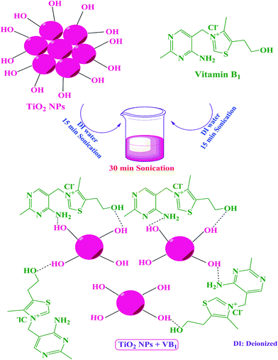
In the first step, 0.20 g of TiO2 NPs was dispersed in 8 ml of deionized (DI) water by ultrasonication for 15 min. Then 0.02 g of VB1 was dissolved in 8 ml of DI water and was ultrasonicated for 15 min to achieve a homogenous solution. In the second step the VB1 solution was added to the TiO2 suspension and ultrasonicated for 30 min to grafting onto the NPs surface (Scheme 1).2.4 Preparation of PVC/TiO2–VB1 NCs
The preparation of PVC/TiO2–VB1 NC films were performed by ultrasonic irradiation technique. PVC (0.10 g) were dissolved in 5 ml THF and stirred for 1 h at 40 °C to achieve a homogenous solution. Modified TiO2 NPs with different contents (3, 5, and 7 wt%) were added into the PVC solution. Then, the above mixtures were ultrasonicated for 30 min, and the resulting solutions were cast onto a glass Petri dish and kept at room temperature to prepare NC films.The images of the prepared NC films with different contents of NPs are shown in Fig. 1. As it can be seen, the transparency of NC films decreased with increasing of the NPs contents.
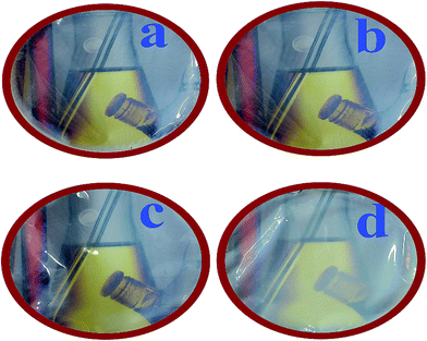 | ||
| Fig. 1 Visual transparency of (a) pure PVC, (b) PVC/TiO2–VB1 NC 3 wt%, (c) PVC/TiO2–VB1 NC 5 wt%, and (d) PVC/TiO2–VB1 NC 7 wt%. | ||
3. Results and discussion
Surface modification of TiO2 NPs with an appropriate modifying agent can decrease the aggregation of NPs. In this study, the surface of TiO2 NPs was treated with VB1 due to its special properties such as non-volatile, low-cost and non-corrosive using ultrasonication technique. Ultrasonic waves create more energy and cause a better connection of modifier on the surface of TiO2. As shown in Scheme 1, coupling agent molecule (VB1) can be adsorbed on the surface of NPs and can react with the OH groups on the surface of NPs. These interactions can prevent agglomeration of the NPs into the polymer. Surface modification with VB1 leads to better dispersion of modified NPs into the PVC matrix.3.1 FT-IR analysis
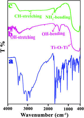
FT-IR is an efficient tool for investigating the structure of polymer composites. Due to the different components of the nanocomposite and the possible interactions between them can be expected to change in FT-IR spectra.29 The FT-IR spectra of bare TiO2, modified TiO2 and VB1 were investigated (Fig. 2). The wide peak in 450–1028 cm−1 for the bare TiO2 (Fig. 2b) is related to the stretching vibration of Ti–O–Ti, and the peaks at 3450 and 1630 cm−1 can be ascribed to the surface hydroxyl groups of TiO2 NPs.30,31 The modified TiO2 (Fig. 2c) shows new bands at 1350 and 1443 cm−1 that are ascribed to C–H vibrations (–CH3 of the pyrimidine ring) and C–H (in –CH3). The band at 1662 cm−1 is attributed to bending vibration of NH (NH2).27 The intensity of OH stretching in the modified TiO2 is found to decrease, indicating an interaction of the hydroxyl group absorbed on TiO2 surface with VB1.The spectra of pure PVC and NCs (3, 5, and 7 wt%) shown in Fig. 3. As is clear from the FT-IR spectrum of the pure PVC (Fig. 3a), the peaks at 616 and 692 cm−1 are ascribed to the stretching vibration of the C–Cl group. The peaks at 1097, 2911 and 2971 cm−1 are related to the C–C, CH and CH2 stretching vibrations.32,33 PVC/TiO2–VB1 NCs (Fig. 3b–d), in addition to specific peaks of TiO2 NPs at 450–800 cm−1, show the characteristic absorption bands at 1532, 1550 and 1629 cm−1 which are related to the stretching vibrations of the C![[double bond, length as m-dash]](https://www.rsc.org/images/entities/char_e001.gif) C and the C
C and the C![[double bond, length as m-dash]](https://www.rsc.org/images/entities/char_e001.gif) N of the pyrimidine ring respectively.
N of the pyrimidine ring respectively.
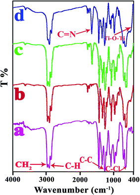 | ||
| Fig. 3 The FT-IR spectra of: (a) pure PVC, (b) PVC/TiO2–VB1 NC 3 wt%, (c) PVC/TiO2–VB1 NC 5 wt%, (d) PVC/TiO2–VB1 NC 7 wt%. | ||
3.2 X-ray diffraction
Fig. 4 shows the XRD patterns of bare TiO2 NPs, modified TiO2 NPs, pure PVC and related NCs with different modified TiO2 percentages. X-ray analysis of bare TiO2 NPs showed seven diffraction peaks at 101, 004, 200, 105, 211, and 204 that are ascribed to the anatase phase, and also at 110, 220, and 301 are related to the rutile phase of TiO2 NPs (Fig. 4a).34,35 All the peaks of bare TiO2 NPs were observed in modified TiO2 NPs that indicating its crystallinity was not affected by the modification. The broad peak in the XRD curve of pure PVC indicated that the PVC is completely amorphous in nature (Fig. 4c).7,36 The XRD of the NCs (Fig. 4d–f) show a monoclinic diffraction line which is related to the crystal plane (101) also the wide noncrystalline peak of the PVC. Therefore, it can be concluded that the morphology of TiO2 was not altered during the sonication process.15 The obtained data from XRD analysis exhibit that the intensity of the peaks corresponds to the TiO2 NPs content. With increasing the TiO2 NPs content, the intensity of the peaks increased.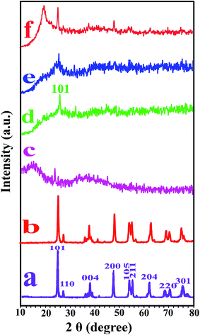 | ||
| Fig. 4 XRD patterns of (a) pure TiO2, (b) modified TiO2, (c) pure PVC, (d) PVC/TiO2–VB1 NC 3 wt%, (e) PVC/TiO2–VB1 NC 5 wt% and (f) PVC/TiO2–VB1 NC 7 wt%. | ||
3.3 Morphological observations
FE-SEM is an effective tool is used for studying the morphology of NCs. The morphology of the products was investigated using the FE-SEM analysis (Fig. 5). As shown in Fig. 5a and b modified TiO2 NPs are in nanoscale with spherical-like morphology. The NPs are nearly same in diameter. The uniform morphology can be observed from FE-SEM images of NCs in 1 μm and 500 nm magnifications (Fig. 5c–h). These photographs indicated good dispersion of modified TiO2 NPs throughout the PVC matrix.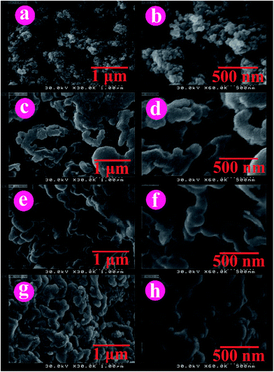 | ||
| Fig. 5 FE-SEM images of (a and b) TiO2–VB1, (c and d) PVC/TiO2–VB1 NC 3 wt%, (e and f) PVC/TiO2–VB1 NC 5 wt%, and (g and h) PVC/TiO2–VB1 NC 7 wt%. | ||
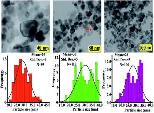
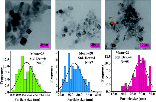
The modified TiO2 NPs and NCs were analyzed by TEM characterization. Fig. 6 and 7 show the TEM images and histograms of the modified TiO2 NPs and PVC/TiO2–VB1 NC 7 wt% at different magnifications respectively. This is clear that modified TiO2 NPs showed various shapes like spherical and cubical with diameters of 28–31 nm in the average size (Fig. 6). It can be seen from NCs images, which the TiO2 particles are in the nano range and uniformly placed into the polymer matrix with the hydrogen bonds (Fig. 7).
3.4 Thermal analysis
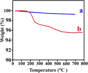
The thermal stability of the polymer NCs is an important issue for use in practical applications. The thermograms of the TiO2 NPs before and after modification are shown in Fig. 8. The bare TiO2 showed a little weight loss of 3.5% within the whole temperature ranging 0–700 °C, which was ascribed to evaporation of the water absorbed by NPs.37 It can be seen that the first degradation for modified TiO2 occurred at 200–300 °C, also the other weight loss appeared within a narrow temperature range of 400–500 °C. Both these weight loss ascribed to the decomposition of VB1 that grafted on the TiO2 NPs.37Weight loss versus temperature for the pure PVC and related NCs shows in Fig. 9. The TGA thermograms of the pure PVC and PVC/TiO2–VB1 NCs undergo two step degradation processes. PVC has a highly tendency to degrade when exposed to heat, shear or radiation (such as UV-light) during melt-processing and practical applications. The degradation begins with a dehydrochlorination reaction and then is accelerated by the released hydrogen chloride (HCl).38 The low stability of pure PVC can be attributed to the presence of structural defects such as head-to-head units, tertiary chlorines at branched carbons and chlorine atoms adjacent to internal double bonds. Heating PVC leads to its degradation and the emission of HCl and the formation of a polyene structure, which happened in the temperature range of 230–350 °C. The polyenes undergo secondary reactions such as scission and crosslinking, leading to the formation of aromatic compounds at the temperature range of 440–570 °C.39,40 As it can be seen, the incorporation of NPs into the PVC matrix increased the thermal stability of all NCs.
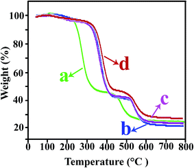 | ||
| Fig. 9 TGA plots of (a) pure PVC, (b) PVC/TiO2–VB1 NC 3 wt%, (c) PVC/TiO2–VB1 NC 5 wt%, and (d) PVC/TiO2–VB1 NC 7 wt%. | ||
Table 1 shows (T5) and (T10) degradations temperature, percentage char yield (CY) at 800 °C, and limiting oxygen index (LOI) of the pure PVC and related NCs. As it is seen, when NPs were incorporated with the PVC matrix, the (T5) and (T10) degradations of all NCs increase and the NCs need more thermal energy for decomposition. In the case of NCs of 3 and 5 wt%, low concentration of nanoparticles and reducing the intermolecular forces after adding nanoparticles lead to more mobility the chains of PVC, therefore the char yield are reduced in comparison to pure PVC at these NCs. But at NC of 7 wt%, high concentration and uniformly dispersion of NPs and strong adhesion between the NPs and polymer matrix, causing the increasing the char yield compared to pure PVC. The char yield can be used for evaluation of limiting oxygen index (LOI) of a polymer in with Van Krevelen and Hoftyzer equation: LOI = 17.5 + 0.4 CY, where CY is the char yield. LOI is the minimum concentration of oxygen that will support combustion of a polymer. A polymer with high LOI has low flammability, so all NCs can be classified as a self-extinguishing materials.13
| Samples | T5a | T10b | Char yieldc (%) | LOId |
|---|---|---|---|---|
| a Temperature at which 5% weight loss was recorded by TGA at a heating rate of 20 °C min−1 under an argon atmosphere.b Temperature at which 10% weight loss was recorded by TGA at a heating rate of 20 °C min−1 under an argon atmosphere.c Weight percentage of material left undecomposed after TGA analysis at a temperature of 800 °C under an argon atmosphere.d LOI evaluating char yield at 800 °C. | ||||
| Pure PVC | 240 | 255 | 23.3 | 26.8 |
| PVC/TiO2–VB1 3 wt% | 287 | 325 | 17.3 | 24.4 |
| PVC/TiO2–VB1 5 wt% | 296 | 329 | 20.2 | 25.6 |
| PVC/TiO2–VB1 7 wt% | 314 | 344 | 24.3 | 27.2 |
3.5 Mechanical properties
Mechanical tests were performed to investigate the effect of NPs on the tensile properties of the pure PVC. Mechanical properties not only depend on shapes, orientations and distribution of fillers, but also depend on the interfacial adhesion between filler and matrix. Generally, nano-additives can improve the mechanical properties of the matrix materials and mechanical stability of NCs tends to increase with increasing values of them.12 Fig. 10 shows the tensile stress–strain curves of the pure PVC and its related NCs. The values of various tensile parameters like Young's modulus, stress, strain and the elongation at break, extracted from all these curves, are listed in Table 2. The strain parameter increase with increasing NPs contents compared with the pure PVC and highest increase is related to the NC of 3 wt%. The stress parameter increases with increasing NPs loading; this can be explained by the reason that the incorporation of TiO2 NPs into the PVC matrix effectively enhanced the interfacial interactions between NPs and matrix via the establishment of hydrogen and covalent bonds between them. As a result, the molecular chain strength of PVC is increased, that can influence the stress of NCs.31 As it can be seen, the Young's modulus, expressed in units of MPa, initially decreases at NC of 3 wt%, in the following increases with increasing NPs contents in both 5 and 7 wt%, but still are less than pure PVC. In general, it can be said that the NCs with large elongation and low modulus can show features of tough materials.14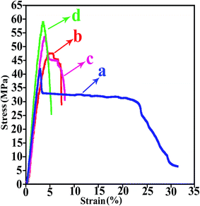 | ||
| Fig. 10 Tensile stress–strain curves of (a) pure PVC, (b) PVC/TiO2–VB1 NC 3 wt%, (c) PVC/TiO2–VB1 NC 5 wt%, and (d) PVC/TiO2–VB1 NC 7 wt%. | ||
| Sample | Stress (MPa) | Strain (%) | Young's modulus (MPa) | Elongation at break (mm) |
|---|---|---|---|---|
| Pure PVC | 42 | 3 | 1973.4 | 0.9 |
| PVC/TiO2–VB1 3 wt% | 47 | 9 | 1267.1 | 4.3 |
| PVC/TiO2–VB1 5 wt% | 55 | 8 | 1702.9 | 3.6 |
| PVC/TiO2–VB1 7 wt% | 59 | 7 | 1864.6 | 3.3 |
3.6 UV-Vis absorption
UV absorption has been used to characterize the TiO2 NPs dispersed in polymer matrix. It is known that TiO2 is an oxide semiconductor and its threshold of absorption is about 385 nm.23 The absorption onset for modified TiO2 NPs changed to around 650 nm that was reported as a red shift and can be assigned to the formation of a charge transfer complex between the surface of the TiO2 NPs and VB1.41The UV-Vis absorption spectra of the pure PVC and related NC films are shown in Fig. 11. The absorbance peaks at λ = 234 and 280 nm are observed for pure PVC assigned to the n–π* and π–π* transition, respectively.8,42 It is clear that the increase in TiO2 NPs contents leads to increase absorption intensity in UV wavelength region. Increased light extinction by the addition of TiO2 NPs into the polymer may be due to both nanofiller ultraviolet absorption and the light scattering.23
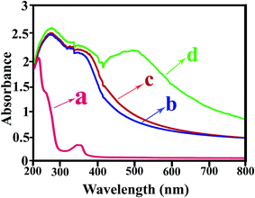 | ||
| Fig. 11 UV-Vis absorption spectra of (a) pure PVC, (b) PVC/TiO2–VB1 NC 3 wt%, (c) PVC/TiO2–VB1 NC 5 wt%, and (d) PVC/TiO2–VB1 NC 7 wt%. | ||
3.7 Contact angle
The contact angle is a natural characterization of the wetting at a solid/liquid interface, straight determining the balance of forces at the three-phase contact line.43 The concept of the contact angle and its equilibrium was important because it gave a definition to the notion of wettability. When θ ≠ 0°, mean that a liquid is nonspreading; and when θ = 0°, say that the liquid wets the solid completely and spreads loosely over the surface at a rate depending on the liquid viscosity and solid surface roughness. On a homogeneous solid surface, angle θ is independent of the volume of the liquid drop. Specifically, when the tendency of the liquid to spread increases as θ decreases, the contact angle is a useful inverse measure of spreadability or wettability.44 The contact angle for pure PVC and the PVC films containing different TiO2 contents are tabulated in Table 3. By increasing the amount of TiO2, the contact angle of the NCs was slightly increased and by elapsing time, the contact angle of the films doesn't change. It is well-known that the water contact angle will increase with increasing surface hydrophobicity.31 The results indicate that increasing the content of TiO2 NPs lead to prevent the spreading of the water drop over the film surface resulting in an increasing of the surface hydrophobicity.45 Therefore, the water resistance of PVC/TiO2–VB1 NC films could be enhanced by adding the desirable amount of TiO2 NPs.46 Fig. 12 shows the images of water droplets on the pure PVC and related NCs.| Samples | Contact angle |
|---|---|
| Neat PVC | 68 ± 0.79 |
| PVC/TiO2–VB1 3 wt% | 77 ± 0.73 |
| PVC/TiO2–VB1 5 wt% | 80 ± 0.81 |
| PVC/TiO2–VB1 7 wt% | 84 ± 0.83 |
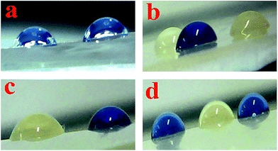 | ||
| Fig. 12 Images of water droplets on (a) pure PVC, (b) PVC/TiO2–VB1 NC 3 wt%, (c) PVC/TiO2–VB1 NC 5 wt%, and (d) PVC/TiO2–VB1 NC 7 wt%. | ||
4. Conclusions
The apparition of new peaks and also shifts in the FTIR spectrum of modified TiO2 certified the presence of VB1 on the surface of NPs. XRD patterns of NC films showed that the morphology of the TiO2 NPs did not alter after incorporation in the PVC matrix and the intensity of the peaks increased with increasing the content of the TiO2 NPs. It is clear from the TEM images of the PVC NCs that, TiO2 NPs uniformly embedded into the polymer matrix. A comparison of T5 and T10 of the NCs with pure PVC showed an increase in thermal stability of PVC/TiO2–VB1 NCs. Also, strain and elongation of NC films were increased compared with the pure PVC. The lower hydrophilic properties of TiO2 NPs caused the enhancement of surface hydrophobicity of PVC NCs in comparison with pure PVC. As a result, we can say that the presence of VB1 as modifier agent can prevent agglomeration of TiO2 NPs and impact on thermal, mechanical, and optical properties of PVC.Acknowledgements
We wish to acknowledge the Research Affairs Division Isfahan University of Technology (IUT), Isfahan, for partial financial support. We are also indebted National Elite Foundation (NEF), Iran Nanotechnology Initiative Council (INIC) and Center of Excellence in Sensors and Green Chemistry Research (IUT) for further financial support.References
- Y.-W. Mai and Z.-Z. Yu, Polymer nanocomposites, Woodhead publishing Ltd, Cambridge, England, 2006 Search PubMed.
- C. Gao and G. Chen, Compos. Sci. Technol., 2016, 124, 52–70 CrossRef CAS.
- Z. Hu and G. Chen, Adv. Mater., 2014, 26, 5950–5956 CrossRef CAS PubMed.
- K. Xu, G. Chen and D. Qiu, J. Mater. Chem. A, 2013, 1, 12395–12399 CAS.
- Y.-Z. Bao, H. Zhi-ming, L. Shen-xing and W. Zhi-xue, Polym. Degrad. Stab., 2008, 93, 448–455 CrossRef CAS.
- H. Wang, G. Xie, Z. Ying, Y. Tong and Y. Zeng, J. Mater. Sci. Technol., 2015, 31, 340–344 Search PubMed.
- M. Hasan and M. Lee, Prog. Nat. Sci.: Mater. Int., 2014, 24, 579–587 CrossRef CAS.
- M. Hasan, R. Kumar, M. Barakat and M. Lee, RSC Adv., 2015, 5, 14393–14399 RSC.
- C. Wang, H. Wang, J. Fu and G. Gu, Colloids Surf., A, 2014, 441, 544–548 CrossRef CAS.
- H. I. Meléndez-Ortiz, C. Alvarez-Lorenzo, A. Concheiro, V. M. Jiménez-Páez and E. Bucio, Radiat. Phys. Chem., 2016, 119, 37–43 CrossRef.
- S. H. Kim, S.-Y. Kwak and T. Suzuki, Polymer, 2006, 47, 3005–3016 CrossRef CAS.
- S. Mallakpour, A. Abdolmaleki and H. Tabebordbar, Eur. Polym. J., 2016, 78, 141–152 CrossRef CAS.
- M. Zarrinkhameh, A. Zendehnam and S. Hosseini, J. Ind. Eng. Chem., 2015, 30, 295–301 CrossRef CAS.
- S. Mallakpour and N. Jarang, J. Vinyl Addit. Technol., 2015 DOI:10.1002/vnl.21526.
- S. Mallakpour and A. Nezamzadeh Ezhieh, Polym. Compos., 2015 DOI:10.1002/pc.23746.
- S. Mallakpour and M. Naghdi, Polym. Bull., 2016, 1701–1717 CrossRef CAS.
- F. Cesano, G. Fenoglio, L. Carlos and R. Nisticò, Appl. Surf. Sci., 2015, 345, 175–181 CrossRef CAS.
- Y. Yang, Z. Ma, L. Xu, H. Wang and N. Fu, Appl. Surf. Sci., 2016, 369, 576–583 CrossRef CAS.
- G. Wang, G. Chen, Z. Wei, T. Yu, L. Liu, P. Wang, Y. Chang and M. Qi, J. Appl. Polym. Sci., 2012, 125, 3871–3879 CrossRef CAS.
- S. Ananthakumar, J. Ramkumar and S. M. Babu, Renewable Sustainable Energy Rev., 2016, 57, 1307–1321 CrossRef CAS.
- F. Feliciano and O. Monteiro, J. Mater. Sci. Technol., 2014, 30, 449–454 CAS.
- E. G. Brandt, L. Agosta and A. Lyubartsev, Nanoscale, 2016 10.1039/C6NR02791A.
- S. Mallakpour and A. Barati, Prog. Org. Coat., 2011, 71, 391–398 CrossRef CAS.
- Y. Zare, Composites, Part A, 2016, 84, 158–164 CrossRef CAS.
- J. Lee, S. L. Bartelt-Hunt, Y. Li and E. J. Gilrein, Chemosphere, 2016, 154, 187–193 CrossRef CAS PubMed.
- C. Poel, S. Bäckermann and W. Ternes, Meat Sci., 2009, 83, 506–510 CrossRef CAS PubMed.
- G. V. Joshi, H. A. Patel, B. D. Kevadiya and H. C. Bajaj, Appl. Clay Sci., 2009, 45, 248–253 CrossRef CAS.
- H. H. Salman, C. Gamazo, M. Agüeros and J. M. Irache, Vaccine, 2007, 25, 8123–8132 CrossRef CAS PubMed.
- K. Deshmukh, S. Khatake and G. M. Joshi, J. Polym. Res., 2013, 20, 1–11 CAS.
- B. K. Deka and T. K. Maji, Composites, Part A, 2011, 42, 2117–2125 CrossRef.
- S. A. Oleyaei, Y. Zahedi, B. Ghanbarzadeh and A. A. Moayedi, Int. J. Biol. Macromol., 2016, 89, 256–264 CrossRef CAS PubMed.
- Z. Dunbai, C. Changgen and J. Demin, J. Wuhan Univ. Technol., Mater. Sci. Ed., 2006, 21, 5–8 CrossRef.
- S. Ramesh and M. Chai, Mater. Sci. Eng., B, 2007, 139, 240–245 CrossRef CAS.
- L. Zhang, L. Chen, H. Wan, J. Chen and H. Zhou, Tribol. Lett., 2011, 41, 409–416 CrossRef CAS.
- Z. Li, C. Huang, L. Guo, L. Cui and B. Zhou, Colloids Surf., A, 2016, 498, 98–105 CrossRef CAS.
- M. Vasanthkumar, R. Bhatia, V. P. Arya, I. Sameera, V. Prasad and H. Jayanna, Phys. E, 2014, 56, 10–16 CrossRef CAS.
- X. Xu, Z. Zhang and W. Liu, Colloids Surf., A, 2009, 341, 21–26 CrossRef CAS.
- J. Liu, G. Chen and J. Yang, Polymer, 2008, 49, 3923–3927 CrossRef CAS.
- J. Yu, L. Sun, C. Ma, Y. Qiao and H. Yao, Waste Manage., 2016, 48, 300–314 CrossRef CAS PubMed.
- K. Endo, Prog. Polym. Sci., 2002, 27, 2021–2054 CrossRef CAS.
- S. Günes, N. Marjanovic, J. M. Nedeljkovic and N. S. Sariciftci, Nanotechnology, 2008, 19, 424009 CrossRef PubMed.
- A. El Sayed, S. El-Sayed, W. Morsi, S. Mahrous and A. Hassen, Polym. Compos., 2014, 35, 1842–1851 CrossRef CAS.
- T. S. Lin, Y. H. Zeng, R. Y. Tsay and S. Y. Lin, J. Taiwan Inst. Chem. Eng., 2016, 26–31 CrossRef CAS.
- W. A. Zisman, Relation of the equilibrium contact angle to liquid and solid constitution, 1964, pp. 1–51 Search PubMed.
- N. A. El-Wakil, E. A. Hassan, R. E. Abou-Zeid and A. Dufresne, Carbohydr. Polym., 2015, 124, 337–346 CrossRef CAS PubMed.
- J. Ren, S. Wang, C. Gao, X. Chen, W. Li and F. Peng, Cellulose, 2015, 22, 593–602 CrossRef CAS.
| This journal is © The Royal Society of Chemistry 2016 |

