
Molecularly imprinted polymer-capped nitrogen-doped graphene quantum dots as a novel chemiluminescence sensor for selective and sensitive determination of doxorubicin†
Mohammad Amjadi* and
Roghayeh Jalili
Department of Analytical Chemistry, Faculty of Chemistry, University of Tabriz, Tabriz 5166616471, Iran. E-mail: amjadi@tabrizu.ac.ir; Fax: +98 4133340191; Tel: +98 4133393109
First published on 5th September 2016
Abstract
In this work, molecularly imprinted polymer-capped nitrogen-doped graphene quantum dots (MIP@NGQDs) were prepared via a simple sol–gel process and used for recognition of the anti-cancer drug, doxorubicin. Strong chemiluminescence (CL) emission was observed when potassium permanganate was injected into the solution of MIP@NGQDs. At the same time, in the presence of doxorubicin the CL intensity was significantly quenched and this was exploited to develop a CL detection scheme for this drug. The mechanism of the MIP@NGQDs/KMnO4 CL system was investigated by recording UV-Vis, fluorescence and CL spectra. Under the optimal conditions, the relative CL intensity linearly decreased with the concentration of doxorubicin in the range of 20–260 μg L−1. The limit of detection was 4.7 μg L−1. The method was applied to the determination of therapeutic levels of doxorubicin in spiked serum samples with satisfactory results.
1. Introduction
Doxorubicin (DOX, Fig. 1), an anthracycline antibiotic, is a clinically important antitumor agent which is widely used in the treatment of a wide variety of cancers. However, long-term clinical use of doxorubicin is limited due to its cytotoxic effects on neoplastic cells through the accumulation of reactive oxygen produced by scavenger enzyme activities.1,2 Therefore, monitoring of the level of this drug in biological fluids of patients during their treatment period is important. Several analytical methods such as high performance liquid chromatography,3–5 fluorescence spectroscopy,6,7 electrochemical sensors8,9 and capillary electrophoresis10,11 have been developed for determination of doxorubicin in biological fluids. | ||
| Fig. 1 Chemical structure of (a) doxorubicin (b) idarubicin (c) daunorubicin. | ||
Chemiluminescence (CL) as an analytical tool show several advantages such as, no interference from background scattering light, simplicity of instrumentation, excellent sensitivity, a wide linear range, low detection limits, ease of automation and versatility for the determination of a wide variety of species.12,13 As the selectivity of the CL methods is usually low, in some circumstances it needs a screening agent to eliminate the interference of coexisting substances.
One approach to improve the selectivity of CL is using molecularly imprinted polymers (MIPs). Molecular imprinting technology is a powerful technique to achieve three dimensional molecular recognition via the template-directed synthesis of highly cross-linked polymeric matrices.14–16 MIPs are generally assembled by polymerization of functional and cross-linking monomers in the presence of a template (target molecule). Subsequent template removal, e.g., by extraction, results in cavities which are complimentary in size, shape and electronic or hydrogen-bonding demand to target molecule and is ready to selectively recognize and bind to it.17
Graphene quantum dots (GQDs) are zero-bandgap carbon-based materials with sizes less than 10 nm. They exhibit some excellent characteristics such as high surface area and good surface grafting by using the π–π conjugated network or abundant surface functional groups. Most reported GQDs are photoluminescent due to the quantum confinement and edge effects. Luminescent GQDs with their superior properties such as excellent solubility, stable photoluminescence, low toxicity, abundance of raw materials in nature and fine bio-compatibility are regarded as next-generation nanomaterials for replacing toxic and expensive semiconductor quantum dots.18,19 However, the quantum yield of GQDs is much lower than that of conventional semiconductor quantum dots. Doping GQDs with heteroatoms (such as nitrogen and boron) can effectively tune their intrinsic properties, including optical characteristics, surface and local chemical features. In nitrogen-doped GQDs (NGQDs), nitrogen atoms which have comparable atomic size and contain five valence electrons, can form strong bonds with carbon atoms.20–22 Besides the excellent PL properties, some carbon nanomaterials were found to have CL activities. They could participate in a CL reaction as emitting species;23–25 as catalysts of a reaction involving others luminophores26,27 or as emitter, after CL energy transfer.28,29
Application of MIP-modified quantum dots in the CL was first introduced by Lin and coworkers30 who used MIP-capped Mn-doped ZnS QDs for determination of 4-nitrophenol using KIO4–H2O2 system. Ge et al. reported a CL sensor based on CdTe QDs and imprinted polymers for deltamethrin.31 To the best of our knowledge, the application of MIP-modified GQDs in CL has not been reported up to now.
In this work, we made a first attempt to prepare MIP-coated NGQDs as CL sensor via a facile sol–gel polymerization process for selective recognition and sensitive detection of DOX. Under the optimal conditions, the MIP@NGQDs sensor was successfully used for determining DOX in real samples. The working principle of sensor is illustrated in Scheme 1.
 | ||
| Scheme 1 Schematic illustration of the fabrication of MIP@NGQDs and the sensing principle for DOX. | ||
2. Experimental
2.1. Apparatus
The CL signals were monitored by LUMAT LB 9507 chemiluminometer (Berthold; www.berthold.com). Fluorescence spectra were recorded by Shimadzu RF-540 fluorescence spectrophotometer (Kyoto, Japan). CL spectrum was recorded with the same instrument using flow mode with the excitation light source being turned off. UV-Vis absorption spectra were obtained by a Cary-100 spectrophotometer (Varian, Australia). The size and structure of NGQDs and MIP@NGQDs were characterized by transmission electron microscopy (TEM) (BioTwin and CM 120, Philips, Netherlands) and scanning electron microscopy (SEM) (Mira 3 FEG, Tescan, Czech Republic). The same SEM system was used for the in situ energy dispersive X-ray spectroscopy (EDX) analysis. Fourier transform infrared (FT-IR) measurement was carried out with a Tensor-27 FT-IR spectrometer (Bruker, Germany). Raman spectrum was recorded using an Almega Thermo Nicolet Dispersive Raman Spectrometer (USA) with a 532 nm laser.2.2. Materials and reagents
All reagents were of analytical grade and used as received. Doubly distilled de-ionized water obtained from Ghazi Serum Co. (Tabriz, Iran) was used for the preparation of all solutions. Aminopropyltriethoxysilane (APTES), potassium permanganate, citric acid and urea were purchased from Merck (Darmstadt, Germany). Tetraethoxysilane (TEOS) was obtained from Sigma-Aldrich (US). Doxorubicin was kindly provided by Exir Nanosina Co (Tehran, Iran), and a 100 mg L−1 stock solution was prepared and stored in a dark bottle at 4 °C.2.3. Synthesis of the NGQDs
The NGQDs were synthesized via a one-step hydrothermal method.32 Briefly, 1.0 g of citric acid and 0.18 g of urea were dissolved in 25 mL deionized water. The solution was sealed into a 50 mL Teflon equipped stainless steel autoclave followed by hydrothermal treatment at 200 °C for 8 h. Then, the reactor was cooled down to room temperature naturally. The pH of the obtained solution was adjusted at 7.0 with NaOH. The obtained NGQDs were diluted to 50 mL with water for further use.2.4. Synthesis of MIP@NGQDs
The imprinting polymer were prepared by sol–gel procedure at the surface of the NGQDs as described in the literature.33,34 Briefly, 10 mL of ethanol and 25 mL of deionized water were added into a 250 mL round-bottom flask. Under vigorous stirring, 25 mL of NGQDs and 80 μL of APTES were added and the mixture was stirred for 2 h. Then, DOX template (20 mg) was dissolved in ultrapure water and injected to the above solution. After stirring for 15 min, 100 μL of ammonia aqueous solution (25%) was added to the above solution. Then, 100 μL of TEOS and 20 mL of ethanol were added drop by drop with a constant-pressure dropping funnel, and the reaction system was sealed and kept under stirring at room temperature for 12 h. Finally, the resultant MIP@NGQD particles were centrifuged and washed with ethanol and distilled water. This step was repeated several times until no template was detected by UV-Vis spectrophotometry. The purified MIP@NGQDs were re-dispersed in deionized water and stored at 4 °C. Nonimprinted nanoparticles (NIP@NGQDs) as a control were prepared similarly, except that the template (DOX) was omitted.2.5. Procedure for CL assay
CL measurements were carried out in the batch conditions. An amount of 400 μL of H2SO4 (2.0 M) and 100 μL of MIP@NGQDs (100 mg L−1) were added into to the reaction tube. Then an appropriate volume of sample or standard solution of DOX was added and the final volume was reached to 700 μL with deionized water. After incubation for 5 min, 100 μL of KMnO4 (4 mM) was injected using an automatic injector and the CL signal versus time was monitored automatically. Maximum CL intensity was used as analytical signal.2.6. Sample preparation
Human serum samples were obtained from Blood Transfusion Center (Tabriz, Iran). A 1.0 mL aliquot of each sample was placed into a centrifuge tube and spiked by adding appropriate volumes of DOX standard solution. Then, 0.5 mL of trichloroacetic acid (10% w/w) was added into the tube in order to precipitate proteins. After centrifugation for 15 min, the clear supernatant was diluted to 10 mL in a volumetric flask and analyzed according to the general procedure.3. Results and discussion
3.1. Characterization of nitrogen-doped NGQDs
Fig. 2a is the TEM image of the as-synthesized NGQDs, which shows that they are fairly uniform and have narrow size distribution in the range of 1.5 and 4 nm. The UV-Vis absorption spectrum of NGQDs is shown in Fig. 2b. A typical peak at 230 nm was observed, which is assigned to the π–π* transition of aromatic C![[double bond, length as m-dash]](https://www.rsc.org/images/entities/char_e001.gif) C sp2 domains. Another obvious absorption peak at 330 nm can be ascribed to the n–π* transition of C–N, which is indicative of N doping in graphene.20 As shown in Fig. 2c, when excited in the range of 320–360 nm, the NGQDs exhibit an excitation-independent photoluminescence centered at 440 nm. Meanwhile, the strongest emission peak corresponds to the excitation wavelength of 330 nm. The well-defined absorption bands and the excitation-independent emission were related to the uniformity of size as well as high crystallinity of the prepared NGQDs. The fluorescence quantum yield of NGQDs was calculated by using quinine sulfate as a standard (54% in 0.1 M H2SO4). A value of ∼43% was obtained at the excitation wavelength of 330 nm.
C sp2 domains. Another obvious absorption peak at 330 nm can be ascribed to the n–π* transition of C–N, which is indicative of N doping in graphene.20 As shown in Fig. 2c, when excited in the range of 320–360 nm, the NGQDs exhibit an excitation-independent photoluminescence centered at 440 nm. Meanwhile, the strongest emission peak corresponds to the excitation wavelength of 330 nm. The well-defined absorption bands and the excitation-independent emission were related to the uniformity of size as well as high crystallinity of the prepared NGQDs. The fluorescence quantum yield of NGQDs was calculated by using quinine sulfate as a standard (54% in 0.1 M H2SO4). A value of ∼43% was obtained at the excitation wavelength of 330 nm.
 | ||
| Fig. 2 (a) TEM image, (b) UV-Vis spectrum, (c) fluorescence spectra at various excitation wavelengths inset: photographs of the aqueous dispersed NGQDs solution under daylight (right) and 365 nm UV irradiation (left), (d) Raman spectrum (the laser excitation wavelength is 532 nm) and (e) FT-IR spectrum of NGQDs. | ||
Raman spectrum also provided a convincing evidence for the graphene structure of the NGQDs (Fig. 2d). The peaks centered at 1290 and 1610 cm−1 are attributed to the D and G bands, which are related to the sp2-bonded C atoms and disordered C atoms at the edges of the NGQDs, respectively. Traditionally, the intensity ratio of “disorder” D to crystalline G (ID/IG) is used to compare the structural order between crystalline and amorphous graphitic systems. The prepared GQDs exhibit small ID/IG value of about 0.4, which indicates the high quality of crystalline graphitic system.
FTIR spectral analysis was used to further characterize the functional groups of NGQDs (Fig. 2e). Broad O–H stretching vibration was appeared at 3430 cm−1. The peak at 1578 cm−1 corresponds to the CC vibration of sp2-hybridized carbon atoms (skeletal vibrations of the aromatic rings). The peak at 1702 cm−1 due to CO stretching proved the presence of a carboxylic acid group. In addition, peaks at 1299 and 1396 cm−1 can be attributed to the C–O and O–H deformation, respectively. The peaks at 1078 and 3250 cm−1 are assigned to the C–N in-plane and N–H in-plane stretching of amine groups, revealing the successful introduction of nitrogen in the NGQDs.
We also quantified the nitrogen content in the NGQDs through EDX experiment. Around 18.5% nitrogen was found to be present in the prepared QDs (Fig. S1, ESI†).
3.2. Preparation and characterization of MIP@NGDs
The MIP@NGQDs were prepared via a sol–gel surface molecular imprinting route. Due to their unique characteristics such as stability in harsh conditions, physical robustness, high surface area, selectivity, as well as low cost and easy preparation, sol–gel MIPs have drawn increased attention both in analysis and sample preparation.35,36 The copolymerization of the NGQDs, APTES (functional monomer), and TEOS (crosslinking monomer) in the presence of template (DOX) forms polymeric network around the template. The subsequent removal of the template using the solvent leaves cavities in the polymer network which are complementary to the template in size and shape.As well as being the functional monomer, APTES also coated the NGQDs surface to provide the nucleation site for TEOS condensation. APTES was chemically modified on the surface of NGQDs by the hydrogen bonding interactions between carboxylic ion groups on the NGQDs and amino groups, leaving the silane group on the other end, from where the hydrolysis occurs and builds up silica shell to permit the following attachment of TEOS molecules.37
MIP@NGQDs suspension exhibited a white color but with the same blue luminescence under 365 nm UV illumination (Fig. 3a). The maximum emission peak of MIP@NGQDs was observed at about 440 nm at the excitation wavelength of 330 nm (Fig. 3a). This is very similar to that of the free NGQDs at the same excitation wavelength (Fig. 2c). This suggests that the fluorescence properties of the NGQDs are not restricted by the silica-based MIP layer, which is logical because silica is optically transparent and chemically inert. Meanwhile, MnO4− can diffuse through the pores of the silica shell to freely exchange electrons with entrapped NGQDs during the CL reaction.38
 | ||
| Fig. 3 (a) Fluorescence spectrum of the MIP@NGQDs (λex = 360 nm, 12.5 mg L−1). Inset: photographs of the aqueous dispersed MIP@NGQDs solution (50 mg L−1) under daylight (right) and 365 nm UV irradiation (left). (b) SEM and TEM (inset) images of MIP@NGQDs. | ||
The SEM image of synthesized MIP@NGQDs is shown in Fig. 3b. From this image, the uniform spherical particle structure with an average diameter of ca. 320 nm and rough surface of MIP@NGQDs could be observed, which verified the successful formation of a desired material shape and morphology. TEM results (Fig. 3a inset) provide further support for highly spherical morphology of MIP@NGQDs.
The FT-IR spectra of MIP@NGQDs (curve 1) and NIP@NGQDs (curve 2) are shown in Fig. S2 (ESI†). They reveal major bands in similar locations, because the compositions of them are similar. The absorption peaks found at 466 and 793 cm−1 are attributed to the Si–O symmetric bending and stretching vibrations, respectively. The broad peak from 950 to 1150 cm−1 indicates the Si–O–Si asymmetric stretching.
The presence of bands around 1554 and 2943 cm−1 indicates the CH2–N and C–H stretching vibrations, respectively. The broad band at 3166 cm−1 and the band at 1664 cm−1 can be ascribed to stretching vibration of N–H, suggesting the existence of the aminopropyl group. This confirms that APTES combined with the surface of the NGQDs and subsequently reacted with the DOX in the imprinted material.
3.3. CL from NGQDs–KMnO4 system
Preliminary investigations showed that the reaction between MIP@NGQDs and KMnO4 in acidic media results in a strong CL emission. The CL kinetic profiles of the KMnO4–MIP@NGQDs before and after addition of DOX are demonstrated in Fig. 4. When 0.5 mg L−1 DOX is added into the CL system the CL intensity significantly diminished. So, the aforementioned CL system can be applied for the determination of DOX. | ||
| Fig. 4 Kinetic CL curves for MIP@NGQDs–KMnO4 CL system (a) in the absence and (b) in the presence of 0.5 mg L−1 of DOX. Conditions: MIP@NGQDs, 5 mg L−1, H2SO4, 0.5 M, KMnO4, 0.2 mM. | ||
To establish the optimal conditions which provide maximums sensitivity together with stable and intense signals for the determination of DOX, chemical parameters, including the kind of acid and the concentrations of KMnO4, H2SO4 and MIP@NGQDs were investigated.
Acidic media is a key factor in permanganate-induced CL systems. Hence, several acids including H2SO4, HCl, H3PO4 and HNO3 in 0.5 M concentration were tested for the MIP@NGQDs–KMnO4 system. The highest CL signal was achieved in H2SO4 solution (Fig. S3, ESI†). Concentration of H2SO4 was optimized in the range from 0.1 to 2.5 M. As shown in Fig. S4 (ESI†), the highest CL signal was obtained at 0.5 M of H2SO4. At higher concentrations the intensity decreased which might be due to the fact that MIP@NGQDs are destroyed in the highly acidic condition. Thus, 0.5 M of H2SO4 was chosen for further work.
The effect of KMnO4 concentration was investigated in the range of 1.2 × 10⁻⁴ − 2 × 10⁻³ M. It was found that CL intensity increased with an increase in the concentration of KMnO4 up to 0.5 mM and then decreased at higher concentrations (Fig. S5, ESI†). This probably is due to the fact that CL signal can be severely absorbed by high concentration of KMnO4.39
The effect of MIP@NGQD concentration in the range of 1.25 to 30 mg L−1 on the CL intensity was also studied. According to the results (Fig. S6, ESI†), the intensity increased by increasing MIP@NGQDs concentration up to 12.5 mg L−1. So, this amount was throughout the work.
Finally, the effect of incubation time on diminishing of the CL intensity in the presence of 100 μg L−1 DOX was investigated. As shown in Fig. S7 (ESI†), the signal decreased rapidly with increasing time in the initial 5 min, after which the curve became flat. Therefore, an incubation time of 5 min was selected for the CL sensor.
3.4 Analytical performance
As shown in Fig. 5, under the optimum conditions, a good linear relationship between the CL intensity and the DOX concentration in the range of 20–260 μg L−1 was obtained. The regression equation was ΔI = 248.42C − 761.7, (R2 = 0.9981), where ΔI = I0 − I is the difference between the CL intensity in the absence of DOX (I0) and in its presence (I), and C is concentration of DOX in μg L−1. The limit of detection (LOD) (3σ) of the method was evaluated to be 4.7 μg L−1 and the relative standard deviation (RSD%) was 2.9% for ten replicate determinations of 100 μg L−1 DOX. By comparison, the regression equation of the NIP@NGQDs was ΔI = 113.72C + 778.32 (R2 = 0.9942) and the linear range was from 60–260 μg L−1. Thus the CL intensity is proportionally quenched larger in MIP@NGQDs than in NIP@NGQDs because there were no tailor-made recognition sites in the NIP@NGQDs. Comparison of the proposed method with some other reported analytical methods for the DOX quantification is shown in Table 1. As can be seen the developed CL sensor has better or comparable analytical performance compared with most of other reported methods.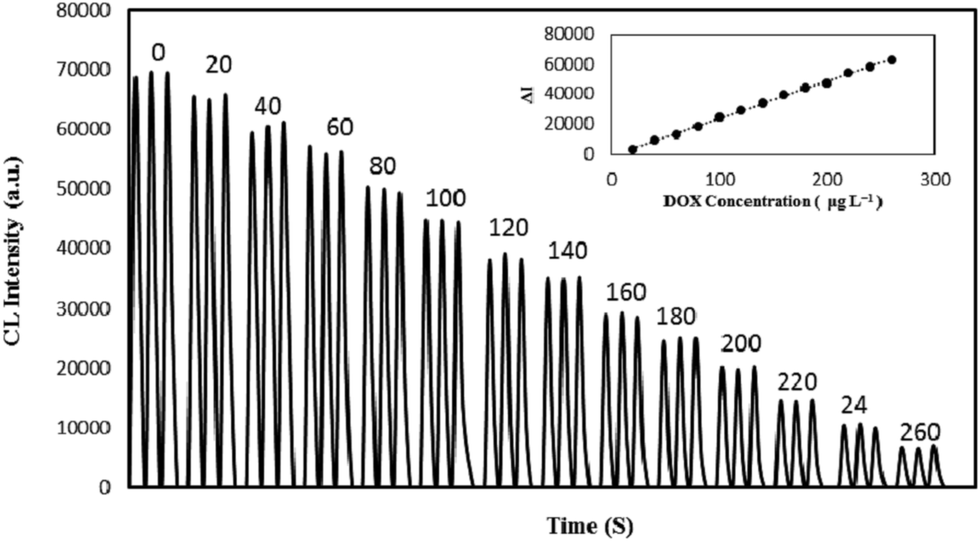 | ||
| Fig. 5 CL profiles of MIP@NGQDs–KMnO4 system in the presence of various concentrations of DOX (μg L−1) and (inset) corresponding calibration graph. Conditions: MIP@NGQDs 12.5 mg L−1, H2SO4, 0.5 M, KMnO4, 0.5 mM. | ||
3.5. Possible CL reaction mechanism
Clarifying the potential mechanism of CL system can be accomplished by determining the emitting species. In this sense, CL, fluorescence and UV-Vis analyses were conducted. A CL spectrum with an emission peak centered at 450 nm was obtained by a fluorescence spectrometer with the xenon lamp turned off (Fig. 6). This is similar to the NGQD fluorescence spectrum (Fig. 2b). Hence, it is reasonable that CL is attributed to the various surface energy traps that existed on the NGQDs. | ||
| Fig. 6 CL spectrum of MIP@NGQDs–KMnO4 system obtained with continuous flow of reagents: MIP@NGQDs (25 mg L−1) and H2SO4 (1 M) in one line and KMnO4 (1 mM) in other line. | ||
CL emission of the MIP@NGQDs–KMnO4 system can be produced by the radiative recombination of oxidant-injected holes and electrons of the MIP@NGQDs.13,24 KMnO4 as a strong oxidant generates the hole-injected MIP@NGQDs. At the same time, electrons can exist in the high energy levels at temperatures above absolute zero.40 Thus, recombination of electron–hole pair can release energy in the form of CL emission.
The UV-Vis absorption spectrum of the MIP@NGQDs–KMnO4 system was also obtained. As shown in Fig. S8 (ESI†), after adding the MIP@NGQDs into acidic KMnO4, the absorption peak of KMnO4 (around 540 nm) decreased significantly. It can therefore be concluded that KMnO4 was used over its reaction with MIP@NGQDs.
In order to further verify the CL phenomena, the effect of thiourea (0.01 M) and DMSO (0.01 M), the hydroxide radical scavengers, and sodium azide (NaN3, 0.01 M), the quencher of singlet oxygen was studied. They exerted no inhibition on the CL system, which indicated that singlet oxygen emitter and hydroxide radical had no role in the CL system.25
Based on these facts, the CL reaction can be described in its simplest form as follows:
| MnO4− + MIP@NGQDs → Mn(II) + MIP@NGQDs* |
| MIP@NGQDs* → MIP@NGQDs + hν (440) |
It should be mentioned that a silica coating not only provide both chemical and physical shielding from the external environment but also improve the chemical and optical stabilities of particles.32
As shown in Fig. S9 (ESI†), DOX can efficiently quench MIP@NGQDs fluorescence. The quenching process might be attributed to excited-state electron transfer from NGQDs to DOX. Electron transfer from excited-state semiconductor QDs to quinones has been studied41 and proposed as a mechanism for fluorescence quenching.6 Since the CL reaction also involves the electron–hole recombination, a similar mechanism can be suggested for its quenching by DOX. Namely the CL of NGQDs is quenched when electron–hole pair could not recombine or the excitation electron could not transfer from valence band to conduction band. As a result of binding of DOX to MIP@NGQDs, the electron transfer between DOX and NGQDs occurs, which in turn causes a disruption to the radiative recombination of electron–hole pairs in NGQDs.
3.6. Selectivity of MIP@NGQDs
We conducted a selectivity test of MIP@NGQDs for two analogues template including Idarubicin (IBN) and Daunorubicin (DBN) (Fig. 1). The CL intensity of the system was recorded in the presence of these drugs in the same manner as described above. As seen clearly from Fig. 7, compared to DOX, much less decrease in the CL intensity of the MIP@NGQDs was observed for these drugs. Moreover, MIP@NGQDs exhibited much higher sensitivity than NIP@NGQDs to DOX. The results confirm the high selectivity of the imprinted MIP@NGQDs CL sensor for detection of DOX, which clearly is due to the fact that a molecule with the complementarity shape and optimal size has more of a chance to bind with the functional group on the binding site in the imprinted cavities. | ||
| Fig. 7 CL quenching of the MIP@NGQDs and NIP@NGQDs in the presence of DOX, IBN and DBN at the same concentration. Conditions: MIP@NGQDs, 12.5 mg L−1, H2SO4, 0.5 M, KMnO4, 0.5 mM. | ||
Furthermore, to assess the ability of the developed sensor to analyze complex biological samples, the effects of some common ions and organic compounds on the determination of 100 μg L−1 DOX were investigated. The tolerable concentrations for interfering species in relative error of <5% were summarized in Table 2. These results demonstrate that the sensor possesses a good selectivity for the determination of DOX in real samples.
| Interfering species | Tolerable concentration (mg L−1) |
|---|---|
| Sucrose, glucose, lactose, tryptophan, alanine, glycine, vitamin B2, creatinine, urea, Na+, K+, Zn2+, Ca2+, Cu2+, Fe3+, Fe2+, Ba2+, Cu2+, Al3+, Mn2+, Cl−, SO42−, CO32−, NO3− | 100 |
| Vitamin B1, tyrosine | 25 |
| Albumin, uric acid | 10 |
3.7. Analysis of real samples
The applicability of the developed method for determination of DOX in human serum samples was demonstrated. Recovery studies were carried out by spiking the samples with DOX in the therapeutic concentration range.44 A summary of the calculated mean DOX concentration for each sample is shown in Table 3. The obtained recoveries ranged from 94.4% to 106.6%, which indicated the usefulness of the MIP@NGQD sensor for analysis in real samples.| Samples | Added (mg L−1) | Found (mg L−1) mean ± RSD (n = 3) | Recovery (%) |
|---|---|---|---|
| Human serum(I) | 0.30 | 0.31 ± 2.1 | 103.3 |
| 0.60 | 0.57 ± 0.7 | 95 | |
| 0.90 | 0.94 ± 1.1 | 104.4 | |
| Human serum(II) | 0.30 | 0.32 ± 0.9 | 106.6 |
| 0.60 | 0.63 ± 2.8 | 105 | |
| 0.90 | 0.85 ± 0.8 | 94.4 |
4. Conclusion
A simple method for the formation of molecular recognition sites on the surface of NGQDs was developed using sol–gel process to obtain a novel and green MIP@NGQDs sensor for CL detection and selective recognition of DOX. Quenching of the CL emitted by the MIP@NGQDs/KMnO4 reaction allows the detection of target analyte as low as 4.7 μg L−1. The sensor showed high sensitivity and recognition selectivity for DOX over analogues compounds. The results obtained from analysis of spiked human serum samples by the developed sensor further demonstrated its applicability for DOX determination in complex real matrices.References
- F. Arcamone, Doxorubicin: anticancer antibiotics, Elsevier, 1st edn, 2012 Search PubMed.
- M. C. Perry, The Chemotherapy Source Book, Lippincott Williams & Wilkins, 4th edn, 2008 Search PubMed.
- K. Alhareth, C. Vauthier, C. Gueutin, G. Ponchel and F. Moussa, J. Chromatogr. B: Anal. Technol. Biomed. Life Sci., 2012, 887–888, 128–132 CrossRef CAS PubMed.
- J. S. Pérez-Blanco, M. M. F. Gatta, J. M. Hernández-Rivas, M. J. G. Sánchez, M. L. Sayalero Marinero and F. González López, J. Chromatogr. B: Anal. Technol. Biomed. Life Sci., 2014, 955–956, 93–97 CrossRef PubMed.
- S. R. Urva, B. S. Shin, V. C. Yang and J. P. Balthasar, J. Chromatogr. B: Anal. Technol. Biomed. Life Sci., 2009, 877, 837–841 CrossRef CAS PubMed.
- P. Li, S. Liu, S. Yan, X. Fan and Y. He, Colloids Surf., A, 2011, 392, 7–15 CrossRef CAS.
- A. V. Schenone, M. J. Culzoni, A. D. Campiglia and H. C. Goicoechea, Anal. Bioanal. Chem., 2013, 405, 8515–8523 CrossRef CAS PubMed.
- N. Hashemzadeh, M. Hasanzadeh, N. Shadjou, J. Eivazi-Ziaei, M. Khoubnasabjafari and A. Jouyban, J. Pharm. Anal., 2016, 6, 235–241 CrossRef.
- M. Taei, F. Hasanpour, H. Salavati and S. Mohammadian, Microchim. Acta, 2016, 183, 49–56 CrossRef CAS.
- X. Yang, H. Gao, F. Qian, C. Zhao and X. Liao, J. Pharm. Biomed. Anal., 2016, 117, 118–124 CrossRef CAS PubMed.
- H. Lu, G. Yuan, Q. He and H. Chen, Microchem. J., 2009, 92, 170–173 CrossRef CAS.
- N. Siraj, B. El-Zahab, S. Hamdan, T. E. Karam, L. H. Haber, M. Li, S. O. Fakayode, S. Das, B. Valle, R. M. Strongin, G. Patonay, H. O. Sintim, G. A. Baker, A. Powe, M. Lowry, J. O. Karolin, C. D. Geddes and I. M. Warner, Anal. Chem., 2016, 88, 170–202 CrossRef PubMed.
- X. Fan, Y. Feng, Y. Su, L. Zhang and Y. Lv, RSC Adv., 2015, 5, 55 Search PubMed.
- G. Liu, T. Li, X. Yang, Y. She, M. Wang, J. Wang, M. Zhang, S. Wang, F. Jin, M. Jin, H. Shao, Z. Jiang and H. Yu, Carbohydr. Polym., 2016, 137, 75–81 CrossRef CAS PubMed.
- Y. Fang, S. Yan, B. Ning, N. Liu, Z. Gao and F. Chao, Biosens. Bioelectron., 2009, 24, 2323–2327 CrossRef CAS PubMed.
- F. Lu, M. Sun, L. Fan, H. Qiu, X. Li and C. Luo, Sens. Actuators, B, 2012, 173, 591–598 CrossRef CAS.
- W. Wan, M. Biyikal, R. Wagner, B. Sellergren and K. Rurack, Angew. Chem., Int. Ed., 2013, 52, 7023–7027 CrossRef CAS PubMed.
- S. Dey, a. Govindaraj, K. Biswas and C. N. R. Rao, Chem. Phys. Lett., 2014, 595–596, 203–208 CrossRef CAS.
- L. Zhang, D. Peng, R. P. Liang and J. D. Qiu, Anal. Chem., 2015, 87, 10894–10901 CrossRef CAS PubMed.
- Z. Cai, F. Li, P. Wu, L. Ji, H. Zhang, C. Cai and D. F. Gervasio, Anal. Chem., 2015, 87, 11803–11811 CrossRef CAS PubMed.
- J. Ju, R. Zhang, S. He and W. Chen, RSC Adv., 2014, 4, 52583–52589 RSC.
- J. Ju and W. Chen, Biosens. Bioelectron., 2014, 58, 219–225 CrossRef CAS PubMed.
- J. Jiang, Y. He, S. Li and H. Cui, Chem. Commun., 2012, 48, 9634–9636 RSC.
- Z. Lin, W. Xue, H. Chen and J. M. Lin, Chem. Commun., 2012, 48, 1051–1053 RSC.
- Z. Lin, W. Xue, H. Chen and J. M. Lin, Anal. Chem., 2011, 83, 8245–8251 CrossRef CAS PubMed.
- Z. Lin, X. Dou, H. Li, Q. Chen and J. M. Lin, Microchim. Acta, 2014, 181, 805–811 CrossRef CAS.
- D. M. Wang, M. X. Gao, P. F. Gao, H. Yang and C. Z. Huang, J. Phys. Chem. C, 2013, 117, 19219–19225 CAS.
- Y. Zhou, G. Xing, H. Chen, N. Ogawa and J. M. Lin, Talanta, 2012, 99, 471–477 CrossRef CAS PubMed.
- X. Dou, Z. Lin, H. Chen, Y. Zheng, C. Lu and J. M. Lin, Chem. Commun., 2013, 49, 5871–5873 RSC.
- J. Liu, H. Chen, Z. Lin and J. M. Lin, Anal. Chem., 2010, 82, 7380–7386 CrossRef CAS PubMed.
- S. Ge, C. Zhang, F. Yu, M. Yan and J. Yu, Sens. Actuators, B, 2011, 156, 222–227 CrossRef CAS.
- C. Wang, J. Qian, K. Wang, M. Hua, Q. Liu, N. Hao, T. You and X. Huang, ACS Appl. Mater. Interfaces, 2015, 7, 26865–26873 CAS.
- R. Jalili and M. Amjadi, RSC Adv., 2015, 5, 74084–74090 RSC.
- J. Hou, H. Li, L. Wang, P. Zhang, T. Zhou, H. Ding and L. Ding, Talanta, 2016, 146, 34–40 CrossRef CAS PubMed.
- V. Samanidou, M. Kehagia, A. Kabir and K. G. Furton, Anal. Chim. Acta, 2016, 914, 62–74 CrossRef CAS PubMed.
- M. M. Moein, M. Javanbakht, M. Karimi, B. Akbari-adergani and M. Abdel-Rehim, Analyst, 2015, 140, 1939–1946 RSC.
- Y. Ma, Y. Li, S. Ma and X. Zhong, J. Mater. Chem. B, 2014, 2, 5043–5051 RSC.
- J. Qian, Z. Zhou, X. Cao and S. Liu, Anal. Chim. Acta, 2010, 665, 32–38 CrossRef CAS PubMed.
- J. L. Adcock, N. W. Barnett, C. J. Barrow and P. S. Francis, Anal. Chim. Acta, 2014, 807, 9–28 CrossRef CAS PubMed.
- H. Chen, L. Lin, H. Li and J. M. Lin, Coord. Chem. Rev., 2014, 263–264, 86–100 CrossRef CAS.
- C. Burda, T. C. Green, S. Link and M. A. El-Sayed, J. Phys. Chem. B, 1999, 103, 1783–1788 CrossRef CAS.
- H. C. Yao, E. J. Xu, W. Y. Zeng, X. Y. Zeng, M. Zhang and J. Chen, J. Food Drug Anal., 2013, 21, 279–285 CrossRef CAS.
- J. Han, J. Zhang, H. Zhao, Y. Li and Z. Chen, J. Pharm. Anal., 2016, 6, 199–202 CrossRef.
- D. R. Barpe, D. D. Rosa and P. E. Froehlich, Eur. J. Pharm. Sci., 2010, 41, 458–463 CrossRef CAS PubMed.
Footnote |
| † Electronic supplementary information (ESI) available. See DOI: 10.1039/c6ra18184h |
| This journal is © The Royal Society of Chemistry 2016 |