Xiaobing Lou‡
,
Huiping Hu‡,
Chao Li,
Xiaoshi Hu,
Tian Li,
Ming Shen
*,
Qun Chen and
Bingwen Hu
School of Physics and Materials Science, Shanghai Key Laboratory of Magnetic Resonance, East China Normal University, Shanghai 200062, China. E-mail: mshen@phy.ecnu.edu.cn
First published on 5th September 2016
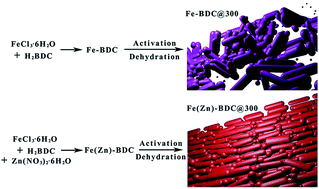
Ferric coordination polymers were synthesized via a hydrothermal process. With the addition of zinc nitrate, the as-prepared Fe(Zn)–BDC@300 shows rod-like morphology and exhibits superior electrochemical performance as an anode material for lithium-ion batteries. It shows a reversible capacity of 863.4 mA h g−1 at 0.1 A g−1 after 120 cycles.
Recently, metal organic frameworks (MOFs), have been applied as anode materials for their excellent capacity and stability in Li-storage.16–21 For example, MOF-177,22 Zn3(HCOO)6,23 Mn-LCP,24 Mn-BTC,25 Co2(OH)2BDC,26 MnCo-BTC,27 BiCPs,28 and CoBTC-EtOH29 have drew plenty of attention. To design an excellent electrode material, one of the most important tasks is morphology control. Better morphology may provide more available lithiation sites to enhance the capacity and achieve higher Li+ ion diffusion rates. From numerous studies, several methods have been used to improve the morphologies of MOFs. One of these methods is changing reaction solvents. CoBTC29 with reaction solvents of DMF (dimethylformamide), DMF/EtOH, and EtOH (ethanol) could be designed to be lamellar crystals consist of irregular walls, laminar crystals consist of nanorods and monodispersed microspheres, respectively. With the novel microspherical morphology, higher specific area, and absence of coordination solvent, CoBTC-EtOH maintained the highest capacity of 473 mA h g−1 at a rate of 2 A g−1 after 500 cycles. Other methods including adding of surfactant (e.g. polyvinyl pyrrolidone or PVP30), changing reaction time have also been reported.31,32
Normally, Fe–BDC MOF can be synthesised by mixing FeCl3·6H2O and H2BDC (terephthalic acid). In this work, we mixed zinc nitrate in the reactants and obtained Fe(Zn)–BDC for the first time. Inductively coupled plasma atomic emission spectroscopy (ICP) tests reveal that there is only little Zn element (∼0.25%) in the Fe(Zn)–BDC. But after activation, the morphology of Fe(Zn)–BDC@300 is greatly changed compared with Fe–BDC@300 obtained with the same activation procedure, as displayed in Fig. 1. Electrochemical tests show that the Fe(Zn)–BDC@300 exhibits greater capacity and better cycling stability as anode in LIBs than Fe–BDC@300.
Fe(Zn)–BDC was solvothermally synthesized with FeCl3·6H2O (10 mmol, Acros, 99%), 1,4-benzenedicarboxylic acid (H2BDC, 10 mmol, Aladdin, 97%), and Zn(NO3)2·6H2O (5 mmol, Aladdin, 99%) in N,N-dimethylformamide (50 mL, DMF, Sinopharm). The reactants were stirred for 10 min at room temperature for a complete dissolution and were transferred into a 100 mL Teflon-lined stainless steel autoclave before heating at 150 °C for 24 hours. After cooling to room temperature, the product was filtered and successively washed by DMF and ethanol for three times respectively to remove surplus reactants. The Fe(Zn)–BDC powder was finally obtained by drying the product at 70 °C for 12 h. As a contrast of Fe(Zn)–BDC, the product Fe–BDC was synthesized without adding Zn (NO3)2·6H2O in the initial reactants.
Fourier transform infrared spectroscopy (FTIR) analysis is a useful method to detect the coordination of metal centers and organic linkers in MOFs. As shown in Fig. 2a, the characteristic bands of H2BDC (νC
O, 1686 cm−1; δC
O, 524 cm−1) are not observed for Fe(Zn)–BDC and Fe–BDC, proving the absence of H2BDC in the resultants. New bands (1537–1599 cm−1, asymmetric stretching vibrations of –COO−; 1387 cm−1, symmetric stretching vibrations of –COO−; 750 cm−1, ring-out-of-plane vibration of the 1,4-substituted benzene core of the linkers) are observed in the two products, indicating the successful coordination between ferric ions and BDC2− ligands.
The PXRD patterns of Fe(Zn)–BDC and Fe–BDC can be found in Fig. 2b. PXRD patterns suggest that the structure of Fe(Zn)–BDC is isostructural to the previously reported MIL-53(Fe)_int, while the structure of Fe–BDC is isostructural to MIL-53(Fe)_lt. Gérard Férey firstly reported MIL-53(Fe)_int and MIL-53(Fe)_lt for their remarkable breathing property. For this kind of Fe-based MOFs, reversible dehydration occurs via the evolution of the structure from more regular phase (MIL-53(Fe)_lt or FeIII(OH){O2C–C6H4–CO2}·H2O) to a highly distorted metastable anhydrous phase (MIL-53(Fe)_int), accompanied by the loss of coordinate water.33,34 It is noteworthy that some amorphous phase could be observed, which is common for MOFs synthesized via the hydrothermal approach.25,29,35
It is obvious that the structure of the MIL-53(Fe) is influenced by the temperature. The thermal behaviour was investigated using thermogravimetric analysis (TGA). As shown in Fig. 2c, continuous weight loss from room temperature to ∼330 °C corresponds to the loss of coordinated water molecules. Above 330 °C, the decomposition of the BDC2− in the skeleton takes place. After the complete break-down of BDC2− ligands at ca. 430 °C, the remnant materials are then converted to Fe2O3. The TGA results also indicate less water content in Fe(Zn)–BDC.
The contents of Fe and Zn elements were estimated by inductively coupled plasma atomic emission spectroscopy (ICP-AES) shown in Table S1, ESI.† Interestingly, very low Zn content (∼0.25%) was found in Fe(Zn)–BDC, which suggests that Fe3+ has much higher coordination ability with the BDC2− ligands, than Zn2+. In fact, this conclusion is consistence with previous reports in which MOF-5 could be used as reactants to form new MOFs via metal ion exchange or postsynthetic exchange (PSE).36–38 The weaker coordination ability of Zn2+ in MOF-5 (Zn–BDC) permits the formation of M-MOF-5 (M = V2+, Cr2+, Mn2+, or Fe2+) with other coordination ions, due to the ion exchange between Zn2+ and another ion such as Fe2+. In another work, Ni-MOF-5 could be directly solvothermally synthesized from Zn(NO3)2 and Ni(NO3)2, which also proves the weaker coordination ability of Zn2+ with the BDC2− ligands.39 In our hydrothermal synthesis, the Zn is involved as followed:40
| 4[Zn(NO3)2·4H2O] + 3[H2BDC] + 8[OH−] ⇌ [Zn4O(BDC)3] + 8[NO3−] + 23[H2O] |
The equilibrium can be shifted to the left side with decreased content of H2BDC that is more easily coordinated with Fe, leading to more favorable products Fe(Zn)–BDC. The formula of Fe(Zn)–BDC and Fe–BDC can be obtained from TGA and ICP-AES results and defined as Fe(OH)(BDC) (H2O)x and Fe(OH)(BDC)(H2O)y, respectively.
Despite the fact that negligible content of Zn was presented in the resultant Fe(Zn)–BDC products, the morphology was modified by adding zinc nitrate in our following thermal activation procedure. We believe that the zinc nitrate could be regarded as structure and morphology-directing agent in this system.
Now we will begin to discuss the heat-activated materials used for LIBs. In order to employ these samples for lithium-ion battery, it is better to remove the water. Therefore, we selected a relatively high temperature of 300 °C to fully remove the coordinated water, according to TGA results. For convenience, the two thermal-treated samples are referred as Fe(Zn)–BDC@300 and Fe–BDC@300, respectively.
Fig. 3 presents FTIR spectra and PXRD patterns and the scanning electron microscope (SEM) images of the two materials obtained after the thermal treatment. Similar FTIR spectra and PXRD patterns demonstrate the structure similarity of anhydrous Fe(Zn)–BDC@300 and Fe–BDC@300. Due to the relatively high temperature of 300 °C to fully active the materials, the PXRD of Fe(Zn)–BDC@300 and Fe–BDC@300 did not match that of the previous reported MIL-53(Fe)_ht,33 which corresponds to anhydrous structure of MIL-53(Fe) activated at a relatively low temperature of 200 °C.
![]() | ||
| Fig. 3 (a) FTIR spectra of Fe(Zn)–BDC@300 and Fe–BDC@300. (b) XRD patterns of Fe(Zn)–BDC@300 and Fe–BDC@300. SEM images of (c) Fe(Zn)–BDC@300 and (d) Fe–BDC@300. | ||
The morphology of Fe(Zn)–BDC@300 is greatly improved compared with Fe–BDC@300 obtained with the same activation procedure. As shown in Fig. 3c, the product Fe(Zn)–BDC@300 shows an apparent nanorods morphology with a diameter of 115–130 nm. In contrast, the Fe–BDC@300 is composed of random-oriented nanorods and irregular nanospheres. The SEM images of Fe(Zn)–BDC and Fe–BDC can be found in Fig. S1.† Besides, the coexistence and homogeneous dispersion of Fe, C and O were displayed in the energy dispersive X-ray spectroscopy mappings (Fig. S2†).
Nitrogen adsorption–desorption isotherms of Fe(Zn)–BDC@300 and Fe–BDC@300 were measured to explore the pore volumes, surface areas and mean pore diameters. As shown in Fig. S3,† IV curves with hysteresis hoops of Fe(Zn)–BDC@300 indicate the mesoporous feature, which is different from that of Fe–BDC@300. By using Brunauer–Emmett–Teller (BET) and Barrett–Joyner–Halenda (BJH) methods, we calculated the specific surface area and corresponding pore (mainly interparticle pores) size distribution which are quite low (Table S2, ESI†). However, this phenomenon is common for other MOFs (e.g. Mn-BTC, Co-BTC). A high surface area often leads to increased side reactions or accessorial secondary reactions with the electrolyte and thus causes capacity decay during cycles. Thus, we believe the appropriate porosity of Fe(Zn)–BDC@300 could provide moderate environment for cell reaction in LIBs.
The cycling behaviours of Fe(Zn)–BDC@300 and Fe–BDC@300 were firstly tested at a low current density of 100 mA g−1 from 0.01 V to 3.0 V versus Li metal reference/counter electrode, as shown in Fig. 4a. With the irreversible capacity loss stemming from electrolyte decomposition to form SEI film, a relatively low coulombic efficiency of 55.14% is found for Fe(Zn)–BDC@300 during the first discharge (1685 mA h g−1) and charge (929 mA h g−1) process. After several cycles, stable SEI film is formed, leading to a coulombic efficiency of nearly 100%. The Fe–BDC@300 electrode got stable after capacity fade for about 20 cycles, only remaining a capacity of 240.0 mA h g−1. After 120 cycles with a rising trend, a discharge capacity of 863.4 mA h g−1 is obtained for Fe(Zn)–BDC@300, which is nearly three times larger than that of Fe–BDC@300.
Rate performance was also studied to further explore the electrochemical capability. Fig. 4b shows the evolution of cycling performance of Fe(Zn)–BDC@300 with an increasing rate from 0.1 to 0.2, 0.5, 1, 2, 4 A g−1. The charge capacities corresponding to these rates are 675 ± 30, 647 ± 15, 552 ± 8, 468 ± 10, 383 ± 13, 294 ± 17 mA h g−1, respectively. After 70 cycles of rate test, the capacity is resumed to 830.8 mA h g−1 at 0.1 A g−1 and retained stable for another 1500 hours. The corresponding charge–discharge capacities of Fe–BDC@300 are 276 ± 28, 224 ± 19, 188 ± 13, 152 ± 9, 110 ± 5, 80 ± 4 mA h g−1, respectively. The Fe–BDC@300 electrode regains its charge–discharge capacity to 442.6 mA h g−1 at 0.1 A g−1, which is much lower than Fe(Zn)–BDC@300.
Fig. 4c shows galvanostatic charge–discharge profiles of Fe(Zn)–BDC@300 electrode within a cutoff voltage of 0.01–3.0 V versus Li/Li+ at 0.1 A g−1. The first discharge profile consists of a wide slope located at 1.04–0.67 V, a sharp slope located at 0.67–0.20 V and a wide plateau below 0.20 V. The discharge curves turn to a sharp slope above 1.0 V and a wide slopebelow 1.0 V in the later cycles. Only minor changes could be observed because of increased capacity. By contrast, the Fe–BDC@300 electrode exhibits much poorer stability (Fig. S5, ESI†). These results prove the higher reversibility of Fe(Zn)–BDC@300.
To further explore the reason of capacity variation in the desolvation process, electrochemical impedance spectroscopy (Fig. 5) was measured in the frequency range of 10 mHz to 1 MHz with an AC amplitude of 10 mV for both Fe(Zn)–BDC@300 and Fe–BDC@300. While the solution resistances (Rs) are only 4.89 Ω and 13.05 Ω, the charge transfer resistances (Rct) are 67 Ω and 288 Ω for Fe(Zn)–BDC@300 and Fe–BDC@300, respectively. The small Rct reflects better Li+ diffusion in Fe(Zn)–BDC@300. Therefore, the improved morphology, increased surface area and smaller charge transfer resistance of Fe(Zn)–BDC@300 in comparison to Fe–BDC@300 are responsible for its greater capacity and better cycling stability.
![]() | ||
| Fig. 5 Impedance spectroscopic study of Fe(Zn)–BDC@300 and Fe–BDC@300 fresh electrodes. Inset: magnified view of the selected high frequency region. | ||
In summary, the introduction of Zn(NO3)2 into the initial reactants has changed the crystalline structure of the Fe–BDC MOF, while the yield Fe(Zn)–BDC product only contain negligible Zn species. After thermal treatment at 300 °C, electrochemical tests show that the Fe(Zn)–BDC@300 exhibits greater capacity and better cycling stability as anode in LIBs than Fe–BDC@300 for its improved morphology, increased surface area, and smaller charge transfer resistance. A reversible capacity of 863.4 mA h g−1 was retained after 120 cycles at a current of 0.1 A g−1 for Fe(Zn)–BDC@300, along with superior rate capability. A postsynthetic exchange (PSE) mechanism could be employed and the zinc nitrate can be regarded as a kind of structure and morphology-directing agent. We believe that this work will provide an alternative way in developing cheap anode materials with excellent performance. Further work will be done to investigate the chemical environment changes of Fe and the charge–discharge mechanism.
Footnotes |
| † Electronic supplementary information (ESI) available: Experimental details, SEM, EDX spectra, nitrogen adsorption/desorption isotherms, galvanostatic charge–discharge profiles, CV curves, ICP data, surface areas and etc. See DOI: 10.1039/c6ra17608a |
| ‡ Equal contribution. |
| This journal is © The Royal Society of Chemistry 2016 |