Enhanced sequestration of large-sized dissolved organic micropollutants in polymeric membranes incorporated with mesoporous carbon

Wei Teng a, Nan Baia, Jianwei Fana, Dandan Lia, Rui Liuc, Jianping Yanga, Wei-xian Zhang*a and Dongyuan Zhao*b
aState Key Laboratory for Pollution Control, School of Environmental Science and Engineering, Tongji University, Shanghai, China 200092. E-mail: zhangwx@tongji.edu.cn
bDepartment of Chemistry, Shanghai Key Laboratory of Molecular Catalysis and Innovative Materials, Advanced Materials Laboratory, Fudan University, Shanghai, China 200433. E-mail: dyzhao@fudan.edu.cn
cMinistry of Education Key Laboratory of Advanced Civil Engineering Material, School of Materials Science and Engineering, Institute of Advanced Study, Tongji University, Shanghai, China 201804

Received 9th July 2016 , Accepted 8th August 2016

First published on 8th August 2016


Abstract

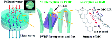
Efficient removal of dissolved organic matter (DOM) is a challenge in advanced water/wastewater treatment, especially for high-molecular-weight polar or charged contaminants. Herein, we report a novel type of self-supported hybrid poly(vinylidene fluoride, PVDF) membrane incorporated with mesoporous carbon. It is fabricated via a simple organic–inorganic mixture and phase inversion process, in which the mesoporous carbon is used as an inorganic additive (up to 40 wt%) for the manipulation of polymeric pore structure and distribution, porosity, thickness, surface area and fouling characteristics. The hybrid membrane combines easy scaleup of polymers and large adsorption capacity of the mesoporous carbon. It possesses high surface areas (up to 550 m2 g−1), three-dimensionally interpenetrating porous structures, improved mechanical strength and chemical property, and favorable water flux (43 to 32 L m−2 h−1). The membrane with 25 wt% of mesoporous carbon shows the best separation performance for large-molecular-sized microcystin-LR (Mw = 995) and Rhodamine B (Mw = 479) (3.8 and 14.8 mg g−1, respectively). Moreover, the complementary properties allow the hybrid membrane be regenerated conveniently and reused with steady cyclic performance. This membrane-forming procedure demonstrates a trade-off relationship of thermodynamics versus kinetics. It is also affected simultaneously by particle–polymer interactions on the micron-sized interfaces during the phase inversion. Results suggest a promising route toward hybrid membranes for efficient sequestration of large-molecules of dissolved organic pollutants.


1 Introduction

Water pollution and the sustainable use of water resources (e.g., reuse of treated wastewater as a drinking water source) are essential issues for human beings. Dissolved organic matter is ubiquitous in surface waters and originates from various sources, prompting serious environmental concerns. It is responsible for water toxicity, color, taste and odor.1–3 For example, microcystin-LR (MC-LR) is a common type of monocyclic heptapeptide produced from cyanobacteria, which is a major environmental issue in blue algae bloom.4–6 Its special cyclic structure, amphipathicity as well as large molecular size of approximately 1.9 × 1.1 × 1.5 nm makes it difficult to remove from water by conventional techniques such as activated carbon sorption, coagulation and filtration.7 Therefore, the efficient control of dissolved organics with large molecular sizes has been recognized as an important part of wastewater treatment/drinking water plants.

Adsorption is an effective approach for water decontamination. Compared with the traditional adsorbents such as microporous activated carbon materials and zeolites, ordered mesoporous materials are regarded as new promising adsorbents. Particularly, the mesoporous carbon materials have exhibited superior adsorption ability to plenty of dissolved organic contaminants,8–10 especially for removal of large-molecular-sized organic pollutants, because they possess good properties with high surface areas, uniform and adjustable mesostructure and pore sizes (>2 nm), large pore volumes, good chemical and thermal stability.11,12 However, the mesoporous carbon materials mainly be used in powdery forms, suffering from low-efficiency separation for regeneration. Therefore, a branch of research has developed for synthesis of rationally designed mesoporous materials to a nanostructured device, capable of low energy and time consumption for convenient removing organics from aqueous systems.13

Recently, membrane technology has attracted growing attention and triggered extensive application on water purification.14–16 Poly(vinylidene fluoride) (PVDF) is one of the most widely used commercial materials in ultrafiltration and microfiltration membrane with regard to its excellent chemical resistance, good mechanical property, and high processability.17 Considerable effort has thus been devoted to tailor the performance of PVDF membranes.18 Among the different methods, blending of inorganic matters through phase inversion is an attractive alternative to modify membrane properties.19 Various nanoparticle materials such as SiO2,20 TiO2,21 Al2O3,22 Fe3O4,23 CNT,24,25 graphene oxides26 and mesoporous silica27,28 have been used to fabricate organic–inorganic hybrid composites to improve the performance of membranes.29 However, reported membranes still show much low removal capacities, especially for large-sized molecules.

Herein, we have designed hybrid mesoporous carbon/PVDF (MC/PVDF) membranes with hierarchical pore structures (mesopores and macropores) through a simple mixture and phase inversion. The combination provides a solution to the upper-bound trade-off limit of the brittleness obstacle of the inorganic membranes and the low separation capacity of the polymeric membranes. Mesoporous carbon materials with different contents (0–40 wt%) are added to survey the influences on the morphology, porosity, mechanical strength and surface properties of these hybrid MC/PVDF membranes. Correlative water permeation, removal performance and recovery capability for large-molecular-sized organics (toxic MC-LR and RhB as representatives) are also evaluated by stacking several layers of the organic–inorganic hybrid membrane as a nanostructured device. It shows a highly efficient water-treatment process and facile regeneration and reuse. Moreover, the formation process of hybrid membranes is investigated.30,31

2 Experimental

2.1 Chemicals

Triblock copolymer poly(ethylene oxide)-b-poly(propylene oxide)-b-poly(ethylene oxide) Pluronic F127 (Mw = 12[thin space (1/6-em)]600, EO106PO70EO106) was obtained from Acros Corp. Tetraethyl orthosilicate (TEOS), phenol, formaldehyde solution (37 wt%), hydrochloric acid, ethanol, polyvinylidene fluoride (PVDF), polyvinylpyrrolidone (PVP), dimethylacetamide (DMAC), Rhodamine B (RhB) and bovine serum albumin (BSA, Mw = 67[thin space (1/6-em)]000) were purchased from Shanghai Chemical Corp. Commercial powder activated carbon (PAC) was supplied by the Xinzhuang Activated Carbon Company of Shanghai. Microcystin-LR (MC-LR, purity > 95%) was purchased from the Express Technology Co., Ltd. Trifluoroacetic acid (TFA, 99% HPLC grade) and methanol (HPLC grade) were obtained from Merck Corp. Deionized water with a resistance of >18.2 MΩ cm−1 was obtained by passing tap water through a Milli-Q system. All chemicals were used as received without any further treatment.

2.2 Preparation of ordered mesoporous carbon

Ordered bimodal mesoporous carbon was prepared according to the method reported by Liu et al.32 It was a pure carbon obtained from a silica–carbon composite carbonized at 900 °C and then followed by silica removal. The composite was obtained from a tri-constituent co-assembly process of Pluronic F127, silica oligomer precursors and phenolic resols in the initial ethanolic solution.

2.3 Preparation of pure and hybrid PVDF membranes

Pure or carbon-based blended PVDF membranes were fabricated by the phase inversion process. In particular, 4.25 g of PVDF and 1.0 g of PVP were dissolved in 21.1 g of DMAC under stirring at 70 °C to get a homogeneous solution. Then, an amount (15, 25 or 40 wt%, mass percentage of carbon materials/PVDF) of ordered mesoporous carbon or powdery activated carbon (300–500 mesh) and 12.8 g of DMAC were added into. After stirring for 24 h at 70 °C, the mixture solution was in a vacuum oven to release the bubbles. Then the solution was cast on a glass plate at 1.0 m min−1 and 40 °C with a casting knife of 200 μm space. After 40 s of pre-evaporation, the glass plate was immersed in a coagulation bath (ethanol[thin space (1/6-em)]:[thin space (1/6-em)]H2O = 1[thin space (1/6-em)]:[thin space (1/6-em)]1) at room temperature. The formed membranes were peeled off and sequentially transferred into the coagulation bath for 1 day to remove the PVP completely. Then the membranes were washed and immersed with distilled water to remove residual solvent. Some membranes were directly hung dry in the air at room temperature for materials' measurements. The rest membranes were kept in distilled water for the filtration tests. Above membranes with different mesoporous carbon addition were named as x%-MC/PVDF, where x stands for the mass percentage of the mesoporous carbon. Pure PVDF membrane was obtained as the same as above procedure but without carbon addition. Activated carbon blended PVDF membrane with 25% addition was noted as 25%-AC/PVDF.

2.4 Dynamic filter/adsorption of microcystin-LR

To evaluate the removal performance of the pure and hybrid PVDF membranes for large molecular contaminants, 4–10 layers of the typical membranes were stacked and assembled into a filter holder (25 mm in diameter). After a buffer run with deionized water for half an hour, targeted pollutant MC-LR (1 mg L−1) or RhB (2 mg L−1) feed solution was continuously pumped through the filter holder with a constant flow rate (0.1 mL min−1 for MC-LR and 2 mL min−1 for RhB) at room temperature. The effluent from the membrane filter was consecutively collected at the preset time intervals. MC-LR or RhB concentrations were measured by high performance liquid chromatography (HPLC) or UV-Vis spectrophotometer. Based on the measurement and calculation, the breakthrough curves and the corresponding removal capacities (at 10% breakthrough point) for MC-LR or RhB were obtained. After one filtration circle, methanol and deionized water were successively pumped through at the same flow rate to elute the membranes for regeneration.

2.5 Characterization of membranes

Microstructures on the surface and the cross-section of the membranes were observed under the Hitachi S-4800 ultrahigh resolution SEM with gold-spraying treatment. The cross-section was prepared by fracturing the membrane at 77 K in liquid nitrogen. Nitrogen adsorption/desorption isotherms were measured with the Micromeritics Tristar 3020 analyzer. Thermogravimetric (TG) analysis was performed on a Mettler Toledo TGA/DSC 1 thermogravimetric analyzer from 40–900 °C (10 °C min−1) under N2 (20 mL min−1). Fourier transform infrared (FTIR) spectra were measured on a Shimadzu IRPrestige-21 Fourier spectrophotometer. The water contact-angle (CA) of the membrane surfaces was measured by a JYSP-180 Contact Angle analyzer based on the sessile-drop method. Tensile strength and elongation-at-break of membrane coupons (20 × 15 mm) were measured with a YG028 tensile tester. Results were received by averaged over three values. Permeation flux and rejection of the membranes were measured by a ultrafiltration experimental system. The permeation tests were carried out with deionized water and BSA solution (1 g L−1), respectively. All experiments were conducted at room temperature with a pressure of 0.1 MPa. The protocol was as follows: the membranes were first compacted at 0.15 MPa for 30 min. Then the flux was recorded every 3 min at 0.1 MPa. After that, BSA solution (in phosphate buffered saline with a pH of 7.4) was replaced by deionized water, and the permeated BSA was collected every 6 min. The concentrations were measured by an UV-spectrophotometer (Shimadzu UV-2450 Japan) at 280 nm. The permeation flux J (L m−2 h−1) was calculated by using the following eqn (1):
 
image file: c6ra17570h-t1.tif(1)
where, Q (L) is the total volume penetrating through the membrane, T (h) is the operation time and A (m2) is the effective filtration area.

After BSA ultrafiltration, the fouled membranes were cross-flow cleaned with NaOH (10 wt%) and pure water successively for 20 min and then refilled with pure water as a feed to measure the reversibility of fouling every 3 min at 0.1 MPa (details about characterization of mesoporous carbon and measurements of MC-LR and RhB are provided in the ESI).

3 Results

3.1 Hybrid membrane design

The design of a nanostructured adsorbent into macroscopic membrane with favourable features of facile synthesis, self-support and operational ease we report herein targets to efficient and fast removal/sequestration of dissolved organic matters with large molecular sizes. The design is outlined in Scheme 1. A desired adsorbent is equipped with excellent sorption features of enough surface areas or spaces to accommodate the large-molecular-sized adsorbates and intense interaction for fast capturing more objectives. The bimodal mesoporous carbon we adopted here exhibits high-efficient adsorption performance for dissolved organic pollutants with large molecular weights according to our previous work.10 Meanwhile, the system needs a medium material as a powerful support, responsible for dispersing and immobilization the mesoporous carbon as well as ensuring a good flux for flowing water stream. The medium material we chose is organic polymer PVDF, which possess good permeability, thermal and mechanical stability, chemical resistance to the feed streams.
image file: c6ra17570h-s1.tif
Scheme 1 Model design and illustration of hybrid mesoporous carbon/PVDF membrane for MC-LR removal.

3.2 Properties of pristine mesoporous carbon

Small-angle X-ray scattering (SAXS) pattern of the pristine mesoporous carbon shows three well-resolved scattering peaks assigned to the 10, 11 and 21 reflections (Fig. S1a), indicating a highly ordered hexagonal mesostructure of space group p6mm. Transmission electron microscopy (TEM) images (Fig. S2) show the representative stripe-like and arranged 2-D hexagonal mesostructure viewed from the [110] and [001] directions. Furthermore, high resolution scanning electron microscope (HRSEM) image (Fig. S2) exhibits highly ordered mesostructures in large domains with fully open pore channels on the surfaces. Nitrogen adsorption/desorption isotherms show typical type-IV curves with two condensation steps in the mesopore ranges (Fig. S1b). The pristine mesoporous carbon possesses a high surface area of 1680 m2 g−1 and a large pore volume of 1.67 cm3 g−1 with two uniform mesopore size distributions centered at 2.8 and 5.5 nm (Table S1).

3.3 Properties of membranes

The combination process of these organic and inorganic (or macroporous–mesoporous) materials as a device is a simple protocol (Scheme 2). The mesoporous carbon materials are dispersed into a homogeneous PVDF mixed solution. Through a phase inversion process, the hybrid membrane is formed. The carbon contents is high up to 40 wt% by adjusting the additive amount of mesoporous carbon. Pure PVDF membrane exhibits a white and homogeneous texture, while the hybrid organic–inorganic membranes show black carbon particles uniformly dispersed into the PVDF polymer matrix (Fig. S3). With increased carbon content (0–40 wt%), the membrane is gradually getting black. A large area of membrane (15 × 10 cm) can be easily obtained and optionally tailored to fit the filter. All the membranes exhibit good flexibility without any obvious cracks or fracture after bending them several times (at least 100).
image file: c6ra17570h-s2.tif
Scheme 2 Route for preparation of hybrid mesoporous carbon/PVDF membrane and optical photographs, SEM and TEM images of the hybrid membrane in detail.

Thermogravimetric (TG) results under nitrogen atmosphere manifest the carbon contents within the hybrid membranes and the thermal stability (Fig. S4). A major weight loss takes place in the range of 340–480 °C, attributed to the decomposition of PVDF.28,33 The final weight losses reduce proportionately in accordance with increased mesoporous carbon particles in the membranes. Moreover, the thermal decomposition temperatures (Td) of the MC/PVDF composite membranes are higher than that of pure PVDF, indicating a better thermal stability.34 These results may ascribed to the interactions between PVDF polymer chains and mesoporous carbon particles which improve the rigidity of PVDF.28

Scanning-electron microscopy (SEM) image (Fig. 1) of the top surface of pure PVDF membrane shows nodular-like structure. With the mesoporous carbon contents increase, more apparent macrovoids are formed and become bigger. The bottom surface of the membrane is slightly different. It shows a denser ruleless macroporous structure, and gradually appears filamentous connection between each micrometer scale surface when the carbon content reaches 40%. The difference on surface polymeric structure is due to the contact interface (top surface is the liquid interface and bottom is the solid glass) where the phase-inversion happens. The inorganic carbon particles are mainly found disorderly arranged on/in the bottom rather than top surface of the membranes, which caused by gravity settling. More particles can be observed when the carbon contents increase, and all are tightly surrounded or half-surrounded by the polymer chains.


image file: c6ra17570h-f1.tif
Fig. 1 SEM images of pure PVDF (a, b) and hybrid mesoporous carbon/PVDF membranes with different carbon contents: 15%-MC/PVDF (c, d), 25%-MC/PVDF (e, f) and 40%-MC/PVDF (g, h). Left column: top surface of membrane; right column: bottom surface of membrane. Mesoporous carbon particles are marked by red circle.

The thickness of membranes is gradually growing from 25 to 80 μm (Fig. 2). Because the addition of mesoporous carbon particles increases the viscosity of the casting solution, under the same casting speed, the membranes are formed with an incremental thickness. From the cross-section, the pure PVDF membrane exhibits a interpenetrating and highly open macroporous but typical microcellular structure. Once the mesoporous carbon particles addition, the enlarged SEM images clearly show that mesoporous carbon particles (marked by red circle) are anchored tightly within the polymeric chains, and simultaneously play important roles to tailor and change the microstructures of membrane. In particular, the polymeric pore structure transforms from a homogeneous microcellular to a topical asymmetric structure with some finger-like holes or caverns, and meanwhile more interfacial voids surrounded the particles are formed. The polymer chains are gradually stretched to slenderly linear connection around the carbon particles (0–25 wt%). Namely, the growing addition of particles causes a certain degree of separation between the polymer. When the carbon content is up to 40 wt%, the morphology of polymer chains changes to numerous nodular-like spheres in a micrometer/sub-micrometer scale with actinoid connection. Interestingly, too much particles encapsulation causes a denser packing of the polymer chains around their interfacial surfaces, which is different from the former membranes. The phenomenon can be explained that not only the inorganic nanostructured materials addition in the casting solution affects the thermodynamics and kinetics, but also the interfaces of micron-sized carbon particles effect polymer chains connection during phase-inversion process. Details are discussed below. Due to the tight anchor by the interpenetrated polymer chains, the hybrid membranes are quite stable without detachment of the carbon particles from the polymer matrix even through intensive water current.


image file: c6ra17570h-f2.tif
Fig. 2 Cross-section SEM images (a, d, g, j), enlarged SEM images (b, e, h, k) and membrane structural model (c, f, i, l) of pure PVDF (a, b, c) and hybrid mesoporous carbon/PVDF membranes with different carbon contents: 15%-MC/PVDF (d, e, f), 25%-MC/PVDF (g, h, i) and 40%-MC/PVDF (j, k, l). Mesoporous carbon particles are marked by red circle.

Nitrogen adsorption/desorption isotherms (Fig. 3 and Table S1) of the hybrid MC/PVDF membranes show representative type-IV curves with two condensation steps in the mesopore range, similar to that of the pristine mesoporous carbon. With the carbon contents adding from 0 to 40 wt%, the surface areas and total pore volumes increase proportionately from 8 m2 g−1 and 0.02 cm3 g−1 (pure PVDF) to 550 m2 g−1 and 0.44 cm3 g−1 (40%-MC/PVDF). Experimental values of the pore textural parameters are relatively smaller than the theoretical values according to the ratios of mesoporous carbon. The reason is that the soft polymer encapsulating the carbon particles may block a small number of open mesochannels on the surface, and thus the inner surface areas can not be detected and utilized completely. The pore sizes match the pristine mesoporous carbon well with the diameters of 2.0 and 5.6 nm. The porosity of the polymeric membrane has a slight rise from 68 (pure PVDF) to 73% (25%-MC/PVDF), and then down to 69% when the carbon content reaches 40%.


image file: c6ra17570h-f3.tif
Fig. 3 Nitrogen sorption isotherms (A) and the corresponding pore size distribution curves (B) of pure PVDF (a) and hybrid mesoporous carbon/PVDF membranes with different carbon contents: 15%-MC/PVDF (b), 25%-MC/PVDF (c) and 40%-MC/PVDF (d).

FTIR spectra (Fig. S5) of the pure and hybrid PVDF membranes show small changes with the mesoporous carbon addition. The weak bands appear at around 1636, 1543 and 1405 cm−1, which are probably ascribed to the C[double bond, length as m-dash]C groups in the surface aromatic structures, and the tiny amounts of quinine C[double bond, length as m-dash]O and C–H groups conjugated in the surface layers.35 This is the characteristic of the mesoporous carbon materials.

The influences of the mesoporous carbon particles addition on the wettability of membranes are investigated. Contact angles (CA) on the bottom surfaces are bigger than top of the membranes (Fig. S6). When the carbon addition is less than 25 wt%, there is no remarkable change on the membrane surface with a water CA of around 77 (top) and 88° (bottom). While the carbon content is as high as 40 wt%, the water CA reaches up to 82 (top) and 110° (bottom). That is, too much carbon addition leads to a change of surface to hydrophobic property. Otherwise it has no obvious effect on the interface. The tensile strength of the pure and hybrid membrane exhibits a gradual upward trend from 0.51 to 1.05 MPa as increased carbon particles are added (Fig. S7). However, the elongation-T-break shows a visually declining trend from 64 to 6%. This implies that the hybrid membranes are becoming stronger at a certain range, but more brittle than the pure PVDF membranes.

The cyclic filtration is performed with continuous pure water and BSA in phosphate buffered saline (PBS) passing through the pure and hybrid membranes (Fig. S8). At the first stage, the pure water flux decreases from 75 to 32 L m−2 h−1 for the membrane with the increasing carbon content. However, although the flux decreases in a certain range with the mesoporous carbon addition, it is still available for application. The followed BSA solution passing through at the second stage, permeation fluxes of all the membranes decrease rapidly (∼34.3 to 23 L m−2 h−1) due to protein fouling. After cleaning, the water flux (flux recover at the third stage) rises again but cannot be restored to the initial value completely, because the protein molecules not only attach onto the polymer chains but also are entrapped in the pores and/or adsorbed on the surfaces of the mesoporous carbons, which is difficult to be removed by hydraulic or chemical cleaning easily. Therefore, the decrease of flux recovery cannot be totally regarded as an inferior fouling resistance for the hybrid membranes. On the contrary, strong adsorption of mesoporous carbon indicates a good removal ability of pollutant as long as the flux of the hybrid membrane is kept in an executable range.

3.4 Removal of dissolved organic pollutants on membranes

The pure or hybrid membranes with different carbon contents as filter media are assembled to a home-made apparatus for continuous separation of large-molecular-sized pollutants in water currents (Fig. 4B inset). The representative pollutant MC-LR with an initial concentration of 1 mg L−1 is pumped through the stacked membranes of several layers (4–10) at 0.1 mL min−1. Generally, the breakthrough curves of the MC-LR effluent concentration show a tremendous improvement of removal capacity as the mesoporous carbon addition increases in the membrane (Fig. 4A). Typically, for the pure PVDF membrane, a rapid rise of concentration at outlet suggests nearly no any effect on MC-LR removal. While the mesoporous carbons are added, for the 15%-MC/PVDF membrane, the breakthrough curve shows a long flat line with essentially low concentration (<0.02 mg L−1 cannot be detected) until up to ∼20 mL of the feed solution passing through. The following trend of the curve is a quick ascent, demonstrating a forthcoming adsorption saturation. Furthermore, with the carbon contents increase, the flat lines of hybrid membranes gradually lengthen to 42 (25%-MC/PVDF) and 68 mL (40%-MC/PVDF), respectively. Meanwhile, the following ascent curves show gradually smaller slopes. This is because increased carbon particles offer more chances to interact with MC-LR molecules, and the molecules diffuse into the interior of the particles, thus increasing the adsorption capacity and slowing the breakthrough time. However, the volume of treated solution is not proportional to the amount of carbon addition, which can be easily compared by using removal ability in an unit mass. When the effluent concentration is 10% of the feed value, it is defined as the breakthrough point to calculate removal capacity. According to this, the removal capacity of the pure PVDF is only 0.03 mg g−1. While the removal capacities are 3.4, 3.8 and 2.8 mg g−1 for hybrid membranes with increased mesoporous carbon contents (15, 25, 40%-MC/PVDF), respectively. The differences can be contributed to the changes of the PVDF structure which are discussed below. In addition, 25 wt% of powder activated carbon mixed PVDF membrane (25%-AC/PVDF) is prepared here for comparison with the membrane 25%-MC/PVDF. Characterizations of morphologies on the surface and cross-section (Fig. S9), structural and textural properties (Fig. S10 and Table S2) are carried out. The adsorption capacity of the pristine mesoporous carbon (132 mg g−1) is higher than that of AC (46 mg g−1) in batch adsorption in our previous work.10 The breakthrough curves show that only about 10 mL of feed solution can be treated for 25%-AC/PVDF compared with ∼40 mL for 25%-MC/PVDF (Fig. S11). It suggests the mesoporous carbon addition into the PVDF membrane is more available than AC for separation of the large-molecular-sized organics.
image file: c6ra17570h-f4.tif
Fig. 4 (A) Breakthrough curves of the MC-LR solutions through different membranes: pure PVDF (a), 15%-MC/PVDF (b), 25%-MC/PVDF (c) and 40%-MC/PVDF (d). (B) Breakthrough curves of the MC-LR solutions through different layers of 25%-MC/PVDF membrane. (C) MC-LR concentrations in permeate solution versus permeate volume during consecutive adsorption–desorption cycles through 25%-MC/PVDF membrane. (D) Removal rate of MC-LR for consecutive cycles through 25%-MC/PVDF membrane. All tests were conducted with a feed concentration of 1.0 mg L−1, flow rate of 0.1 mL min−1, at pH of 7.0. Inset of (B) is the optical photographs of the experimental unit for the dynamic adsorption.

Different stacking layers of membranes can be easily assembled in the home-made apparatus. The breakthrough curves of 25%-MC/PVDF membranes by using four and ten layers are investigated on MC-LR removal respectively (Fig. 4B). The membrane with four pieces shows about 12 mL of permeation volume at 10% breakthrough point, which is less than two fifth of that by a stack of ten layers (44 mL). The increased layers signify the growing hydraulic retention time. It implies that dwell time is important for an improved removal capacity. Guarantee an available permeability, the membranes could be simply stacked together to enhance the removal capacity.

A continuous recycling of the membrane 25%-MC/PVDF for MC-LR removal is executed (Fig. 4C). For an adsorption–desorption cycle, 10 mL of MC-LR feed solution permeates and then the membrane is rinsed with methanol and water to recover the adsorption capacity. At the adsorption stages, MC-LR can be thoroughly removed from water, and in the following elution cycle, it can be completely desorbed for membrane regeneration. It shows such circle can be repeated at least 6 times with just <5% decline of removal rate in such adsorption–desorption tests (Fig. 4D). Moreover, the eluted MC-LR in methanol can be recovered and collected by evaporation. After six cycles, the SEM image shows no obvious changes in the structures of membrane (Fig. S12). These results indicate that stable mechanical and chemical properties of PVDF as well as well tightly anchored mesoporous carbon particles in the polymer chains benefit a long-term use.

Organic dye Rhodamine B is also selected as a model to evaluate the filtration and adsorption performance on 25%-MC/PVDF membrane (two layers, Fig. S13). Over 25 mL of suspension can be processed, compared to pure PVDF membranes with poor removal performance (<1 mL). The removal capacity is 14.8 mg g−1 for the hybrid membrane. It also exhibits almost unaltered removal rate (97%) after six consecutive adsorption–desorption cycles.

4 Discussion

Mesoporous carbon as a non-solvent additive has an inevitable influence on the microstructure, properties and performances of the hybrid membranes, only depending on its content. Mechanism may be supposed as follows. Rigid inorganic carbon particles (micron-scale) are adequately mixed but not dissolved into the PVDF casting solution at the beginning. When a small amount of carbon is added (15–25 wt%), it reduces the miscibility of casting solutions, resulting in thermodynamic enhancement for a faster phase separation.36 As a result, the increased demixing rate induces a rapid collapse of polymer molecules and concurrent formation of more voids surrounded the particles (Fig. 2e and h). Such structural changes are favor for high water flux. But on the other hand, the mesoporous carbon has poor permeability. The carbon addition makes a high pressure in flowing water stream, which overwhelms advantage of the pore structure changes, finally resulting in a slight decreased flux. Furthermore, for the MC-LR removal, the adsorption capacity increases from 3.4 (15%-MC/PVDF) to 3.8 mg g−1 (25%-MC/PVDF). It can be explained that with the generated voids, the polymer defect is dominant over the pore blockage at the polymer-filler interphase, and more effective exposure of mesoporous carbon surface gives an improved sorption capacity. With further increment of carbon content to 40 wt%, too much non-solvent additives induce the increase in solution viscosity, leading to kinetic hindrance against phase separation. The kinetic hindrance may overwhelm the thermodynamic impact, and solution demixing is delayed. This causes the densest packing of polymers (Fig. 2k), bringing to a low water flux. For MC-LR removal, increased pore blockage by the tightly packed polymers further causes a decreased adsorption performance. In addition, the membrane forms via immersion precipitation in the coagulation bath medium, where hydrosoluble PVP additive is removed but solid particles are left in the PVDF frameworks. Flexible polymer tightly wrapped carbon particles, which makes particles hard to fall off from the membrane and then gives a stable cycle performance. Meanwhile, the addition of rigid carbon is equivalent to increase numerous micron–scale interfaces. The micro-interfaces block the path of the interconnected polymer as well as impact the formation of polymer. It may be the reason that polymer structure gradually be stretched to slenderly linear connection with increased carbon addition, and finally forms numerous nodular-like spheres with actinoid connection. Generally, the whole process is a trade-off relationship against thermodynamics and kinetics, and affected simultaneously by interfaces between polymers and inorganic particles.

As we have designed, above efficient removal of large-molecular-sized organics on the hybrid membranes is well correlated with the novel component and structure, combing the advantages of inorganic and organic materials (Scheme 1). The high-porosity and 3D-interconnected macropores of the PVDF matrix supply enough spaces for the feed solution to easily pass through the membrane. It also possesses good chemical durability and mechanical strength for long-term use as a device with ease of operation. But the pure polymeric PVDF nearly does not give any effective adsorption or rejection toward MC-LR, because the interaction between PVDF and MC-LR (or RhB) is weak, and meanwhile the macropores are too large to intercept the MC-LR (or RhB) molecules. As a complementary part, the mesoporous carbon particles anchored within the PVDF membranes provide plenty effective adsorption active sites (π–π bond) and a proper pore diameter to capture and hold the passing MC-LR (or RhB) molecules, leading to a rapidly enhanced removal performance.

5 Conclusions

In summary, we have rationally designed and developed a self-supported mesoporous carbon/PVDF membranes with ease of operation for targeted removal/sequestration of dissolved organic pollutants with large molecular size, capable of an efficient and fast process. The fabrication of hybrid membrane is facile by easy organic–inorganic mixture and phase inversion. Mesoporous carbon as an inorganic additive affects the phase inversion, and further the properties and performance of the membranes. The procedure of membrane formation is a trade-off relationship against thermodynamics and kinetics, and affected simultaneously by interfaces between polymers and inorganic particles. Results show the hybrid membrane with 25 wt% carbon content exhibits well over-all properties with proper hydrophilicity (78.2°), tensile strength and water flux (42 L m−2 h−1). Such membrane has a significantly enhanced adsorption performance for MC-LR and RhB removal (3.8 and 14.8 mg g−1, respectively) compared to traditional pure PVDF or AC/PVDF membrane. Moreover, stably chemical and mechanical properties make the membrane can be conveniently reused with steady cyclic performance. The hybrid membranes combine the benefits of both flexible (organic PVDF) and rigid (inorganic carbon) materials. Namely, three-dimensional macroporous polymer matrix supplies enough strength and good throughput filtration for high flux and mesoporous carbon anchored in the PVDF offers enough adsorption sites and interfaces for effective pollutant removal. Considering all the merits, the hybrid membrane is a promising filter for high-effective separation and enrichment of targeted pollutants especially the large-sized molecules in advanced water treatment.

Acknowledgements

The authors would like to acknowledge the financial support provided by Shanghai Scientific Research Plan Project (14R21411300), China Postdoctoral Science Foundation (2014M561520), the National Key Basic Research Program (2013CB934104 and 2012CB224805), Shanghai Nanotech Promotion Center (0852nm00100), and the State Key Laboratory of Pollution Control and Resource Reuse Foundation (No. PCRRF12001).

Notes and references

  1. A. Philippe and G. E. Schaumann, Environ. Sci. Technol., 2014, 48, 8946 CrossRef CAS PubMed .
  2. C. Volk, L. Wood, B. Johnson, J. Robinson, H. W. Zhu and L. Kaplan, J. Environ. Monit., 2002, 4, 43 RSC .
  3. A. M. Kennedy and R. S. Summers, Environ. Sci. Technol., 2015, 49, 6617 CrossRef CAS PubMed .
  4. C. Svrcek and D. W. Smith, Environ. Sci. Technol., 2004, 3, 155 CAS .
  5. H. Li and G. Pan, Environ. Sci. Technol., 2015, 49, 6249 CrossRef CAS PubMed .
  6. X. Wu, B. Xiao, R. Li, C. Wang, J. Huang and Z. Wang, Environ. Sci. Technol., 2011, 45, 2641 CrossRef CAS PubMed .
  7. T. Lanaras, C. M. Cook, J. E. Eriksson, J. A. O. Meriluoto and M. Hotokka, Toxicon, 1991, 29, 901 CrossRef CAS PubMed .
  8. X. Zhuang, Y. Wan, C. M. Feng, Y. Shen and D. Y. Zhao, Chem. Mater., 2009, 21, 706 CrossRef CAS .
  9. W. Teng, Z. X. Wu, D. Feng, J. W. Fan, J. X. Wang, H. Wei, M. J. Song and D. Y. Zhao, Environ. Sci. Technol., 2013, 47, 8633 CAS .
  10. W. Teng, Z. X. Wu, J. W. Fan, H. Chen, D. Feng, Y. Y. Lv, J. X. Wang, A. M. Asiri and D. Y. Zhao, Energy Environ. Sci., 2013, 6, 2765 CAS .
  11. Z. J. Li, W. F. Yan and S. Dai, Langmuir, 2005, 21, 11999 CrossRef CAS PubMed .
  12. A. Stein, Z. Y. Wang and M. A. Fierke, Adv. Mater., 2009, 21, 265 CrossRef CAS .
  13. H. W. Liang, X. Cao, W. J. Zhang, H. T. Lin, F. Zhou, L. F. Chen and S. H. Yu, Adv. Funct. Mater., 2011, 21, 3851 CrossRef CAS .
  14. H. Huang, K. Schwab and J. G. Jacangelo, Environ. Sci. Technol., 2009, 43, 3011 CrossRef CAS PubMed .
  15. T. Noeiaghaei, J. Kim and S. Chae, Curr. Org. Chem., 2014, 18, 2381 CrossRef CAS .
  16. M. M. Pendergast and E. M. V. Hoek, Energy Environ. Sci., 2011, 4, 1946 CAS .
  17. F. Liu, N. A. Hashim, Y. Liu, M. R. M. Abed and K. Li, J. Membr. Sci., 2011, 375, 1 CrossRef CAS .
  18. W. Zhang, Y. Zhu, X. Liu, D. Wang, J. Li, L. Jiang and J. Jin, Angew. Chem., Int. Ed., 2014, 53, 856 CrossRef CAS PubMed .
  19. P. Wang, J. Ma, F. Shi, Y. Ma, Z. Wang and X. Zhao, Ind. Eng. Chem. Res., 2013, 52, 10355 CrossRef CAS .
  20. L. Yu, Z. Xu, H. Shen and H. Yang, J. Membr. Sci., 2009, 337, 257 CrossRef CAS .
  21. S. J. Oh, N. Kim and Y. T. Lee, J. Membr. Sci., 2009, 345, 13 CrossRef CAS .
  22. F. Liu, M. Abed and K. Li, J. Membr. Sci., 2011, 366, 97 CrossRef CAS .
  23. Z. Huang, F. Zheng, Z. Zhang, H. Xu and K. Zhou, Desalination, 2012, 292, 64 CrossRef CAS .
  24. K. Kim and S. Park, Macromol. Res., 2010, 18, 981 CrossRef CAS .
  25. J. N. Coleman, U. Khan, W. J. Blau and Y. K. Gun Ko, Carbon, 2006, 44, 1624 CrossRef CAS .
  26. J. G. Zhang, Z. W. Xu, W. Mai, C. Y. Min, B. M. Zhou, M. J. Shan, Y. L. Li, C. Y. Yang, Z. Wang and X. M. Qian, J. Mater. Chem. A, 2013, 1, 3101 CAS .
  27. J. Fan, D. Li, W. Teng, J. Yang, Y. Liu, L. Liu, A. Alghamdi, A. Elzatahry, Y. Deng, G. Li, W. Zhang and D. Zhao, J. Mater. Chem. A, 2016, 4, 3850 CAS .
  28. C. Liao, J. Zhao, P. Yu, H. Tong and Y. Luo, Desalination, 2010, 260, 147 CrossRef CAS .
  29. P. Vandezande, L. E. M. Gevers and I. F. J. Vankelecom, Chem. Soc. Rev., 2008, 37, 365 RSC .
  30. H. Vinh-Thang and S. Kaliaguine, Chem. Rev., 2013, 113, 4980 CrossRef CAS PubMed .
  31. M. Sadrzadeh and S. Bhattacharjee, J. Membr. Sci., 2013, 441, 31 CrossRef CAS .
  32. R. Liu, Y. Shi, Y. Wan, Y. Meng, F. Zhang, D. Gu, Z. Chen, B. Tu and D. Zhao, J. Am. Chem. Soc., 2006, 128, 11652 CrossRef CAS PubMed .
  33. C. Y. Lai, A. Groth, S. Gray and M. Duke, Water Res., 2014, 57, 56 CrossRef CAS PubMed .
  34. Y. Shen and A. C. Lua, Chem. Eng. J., 2012, 192, 201 CrossRef CAS .
  35. C. Moreno-Castilla, M. V. Lopez-Ramon and F. Carrasco-Marin, Carbon, 2000, 38, 1995 CrossRef CAS .
  36. M. J. Han and S. T. Nam, J. Membr. Sci., 2002, 202, 55 CrossRef CAS .

Footnotes

Electronic supplementary information (ESI) available. See DOI: 10.1039/c6ra17570h
These authors contributed equally to this work.

This journal is © The Royal Society of Chemistry 2016
Click here to see how this site uses Cookies. View our privacy policy here.