Ammonia and iron cointercalated iron sulfide (NH3)Fe0.25Fe2S2: hydrothermal synthesis, crystal structure, weak ferromagnetism and crossover from a negative to positive magnetoresistance

Xiaofang Lai a, Zhiping Linb, Kejun Buc, Xin Wanga, Hui Zhangc, Dandan Lib, Yingqi Wanga, Yuhao Gua, Jianhua Lin*a and Fuqiang Huang*ac
aBeijing National Laboratory for Molecular Sciences, State Key Laboratory of Rare Earth Materials Chemistry and Applications, College of Chemistry and Molecular Engineering, Peking University, Beijing 100871, China. E-mail: huangfq@pku.edu.cn; jhlin@pku.edu.cn
bResearch & Development Center for Functional Crystals, Beijing National Laboratory for Condensed Matter Physics, Institute of Physics, Chinese Academy of Sciences, Beijing 100190, China
cState Key Laboratory of High Performance Ceramics and Superfine Microstructure, Shanghai Institute of Ceramics, Chinese Academy of Sciences, Shanghai 200050, China

Received 9th July 2016 , Accepted 18th August 2016

First published on 19th August 2016


Abstract

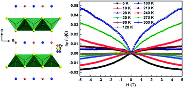
The discovery of superconductivity in anti-PbO-type FeS has aroused a renewed interest in the intercalation compounds of FeS. Here we report a novel intercalation compound of FeS with the chemical composition of (NH3)Fe0.25Fe2S2, which is synthesized via a new hydrothermal reaction. This material crystallizes in the tetragonal space group I4/mmm, preserving the FeS tetrahedral layers with ammonia and excess iron forming planes in between. The microstructure and thermal stability of the sample were studied by scanning electron microscopy (SEM), transmission electron microscopy (TEM) and thermogravimetric analyses (TGA). These results suggest that (NH3)Fe0.25Fe2S2 is not sensitive to electron beam irradiation and is more thermally stable than the other ammonia intercalated iron selenide superconductors. Physical property measurements show that it is a ferromagnetic semiconductor. By using first-principles calculations we assess that the low-temperature ferromagnetism originates from the interlayer rather than the intralayer iron. The transport properties at low temperatures are dominated by electron-like carriers and the sign reversal and strong temperature dependence of the Hall coefficient may be caused by a multi-band effect. Most importantly, an unusual crossover from negative to positive magnetoresistance with increasing temperature was identified, which reveals relatively strong coupling between carriers and magnetic moments as well as disorder.

Introduction

Layered transition metal compounds continue to attract considerable attention because of their rich structural diversity and interesting physical properties such as colossal magnetoresistance (CMR) and high-temperature superconductivity.1 Among them, the layered iron-based compounds composed of alternating FeX (X = pnictogen, chalcogen) tetrahedral layers and various spacer layers are currently extensively studied as promising high-temperature superconductors.2 Like the CuO2 plane in cuprate superconductors, the FeX layer which is made up of edge-sharing FeX4 tetrahedra acts as conducting layer and is responsible for superconductivity. It is accepted that the geometry of FeX4 tetrahedra together with the antiferromagnetic spin fluctuations plays important roles in the superconducting properties.3

Within the iron-based superconductors, FeSe has the simplest crystal structure, consisting of only anti-PbO-type FeSe layers and with no spacer layers.2b The Tc of FeSe is relatively low as 8 K, but this can be greatly enhanced not only by chemical doping and external pressure but also by intercalation.4 The first intercalation compound of FeSe is KxFe2−ySe2 (Tc ∼ 30 K), which has a similar structure to Ba1−xKxFe2As2 superconductor.5 A peculiar feature of KxFe2−ySe2 is that holelike Fermi surface is absent near the Brillouin zone centre, which implies interband scattering may not be a dominant pairing mechanism for iron-based superconductors.6 However, the phase separation in this system makes it difficult to investigate the underlying physics in more detail.7 It is found that except K, Rb, Cs, Tl and Na, other metal or complex spacer layer is difficult to be intercalated in between the FeSe layers via high-temperature solid state reaction. Thereafter, various low-temperature synthetic routes were developed and a series of superconductors AxByFe2Se2 (A = alkali metal, alkaline metal, rare-earth metal, B = NH3; A = alkali metal, B = pyridine, ethylenediamine, hexamethylenediamine), AxFe2Se2 and Li1−xFexOHFeSe were obtained with Tc ranging from 30 to 46 K.8 It should be noted that most of these intercalation compounds are known only by the fact that they are superconductive, while their precise crystal structures as well as other underlying physical properties are less investigated due to the samples being thermally non-stable or air-sensitive. More new related materials with high crystallinity and stability are needed to better understand the structure and properties of this family of compounds. Besides, for Ax(NH3)yFe2Se2, the NH3 molecule plays an important role in stabilizing the structure, and thus it is interesting to see whether there exist A-free NH3 intercalated compounds.

Recently, superconductivity at 5 K was realized in high-quality anti-PbO-type FeS sample which is synthesized by the hydrothermal reaction of iron powder with sulfide solution.9 This has evoked a renewed interest in FeS as well as in the intercalation compounds of FeS.10 It is suggested that the superconductivity in FeS is multi-band and strongly anisotropic; in the normal state, FeS exhibits nonlinear Hall effects and huge positive magnetoresistance (MR), quite different from the small positive MR phenomena observed in other iron-based superconductors.11 As to the intercalation compounds of FeS, efforts made previously have got limited examples such as AxFe2−yS2 (A = alkali metal) and Li1−xFexOHFeS, which are isostructural to AxFe2−ySe2 and Li1−xFexOHFeSe, respectively, and both are semiconducting.12 Attempts to intercalate Na and CaO layer into FeS result in NaFe1.6S2 and Ca2O3Fe2.6S2, respectively, but these new phases do not maintain the FeS tetrahedral layers.13 Even now, when high-quality superconducting FeS samples are available, the family of FeS intercalates have not been enlarged. One of the major reasons is the methodology used in preparing intercalation compounds of FeSe is not applicable to the case in FeS due to that FeS precursor is not strictly dehydrated.

Here we report a new hydrothermal method to synthesize a novel FeS intercalate with chemical composition of (NH3)Fe0.25Fe2S2. It represents the first A-free NH3 intercalated iron chalcogenide, which is highly crystalline and more thermally stable than the other ammonia intercalated iron selenide superconductors. Meanwhile, it is also a rare example of NH3 intercalation by one-step hydrothermal method. In contrast to FeS which is a superconductor, (NH3)Fe0.25Fe2S2 is a ferromagnetic semiconductor and no superconductivity is observed down to 2 K. First-principles calculations reveal that the low-temperature ferromagnetism originates from the interlayer rather than the intralayer iron. Hall effect measurement suggests electron-type carriers at low temperatures and the sign reversal and strong temperature dependence of RH may be caused by multi-band effect. Most interestingly, (NH3)Fe0.25Fe2S2 exhibits a novel crossover from negative to positive MR with increasing temperature which can be explained by disorder effects and spin-dependent scattering mechanism.

Experimental

Chemicals

Iron powder (Alfa Aesar, ≥99%), (NH4)2S aqueous solution (Sinopharm, 8%, w/w) and NaOH pellets (Sinopharm, 98%) were used as received.

Synthesis of (NH3)Fe0.25Fe2S2

Polycrystalline (NH3)Fe0.25Fe2S2 was prepared by a facile one-step hydrothermal reaction. 2 g of Fe powder and 19 mL of (NH4)2S aqueous solution were placed in a 25 mL Teflon-lined autoclave. 1.2 g of NaOH pellets were added as mineralizer. The autoclave was tightly closed and heated at 150 °C for 30 days. After being cooled to room temperature, the products were washed with water and ethanol and dried in vacuum. The yield is ca. 80% with respect to Fe.

Characterization

Powder X-ray diffraction (PXRD) pattern was collected at room temperature on a Bruker D8 Focus X-ray diffractometer operated at 40 kV voltage and 40 mA current using Cu Kα radiation (λ = 1.5406 Å). The 2θ range was 5–110° with a step size of 0.02°. Indexing and Rietveld refinement were performed using the DICVOL91 and FULLPROF programs,14 respectively. Elemental analysis was carried out by inductively coupled plasma-atomic emission spectrometry (ICP-AES) and CHN elemental analyzer. Scanning electron microscopy (SEM) images were taken on a Hitachi S-4800 microscope equipped with an electron microprobe analyzer for the semiquantitative elemental analysis in the energy dispersive X-ray spectroscopy (EDX) mode. Transmission electron microscopy (TEM) images and selected area electron diffraction (SAED) patterns were obtained from a JEOL JEM-2100F microscope operating at 200 kV. Thermogravimetric analyses (TGA) were carried out using a Q600SDT thermal analyzer under N2 atmosphere in the temperature range of 30–600 °C. The samples were examined by powder X-ray diffraction immediately after the TGA experiments.

Physical properties measurements

The magnetic susceptibility was measured with a magnetic field of 10 kOe, in both zero-field-cooling and field-cooling processes. The magnetic hysteresis was recorded at 2 K and 300 K. The resistivity measurement was conducted through the standard four-wire method. The Hall resistance and magnetoresistance were measured by sweeping the magnetic field at a fixed temperature. All these measurements were performed in a physical property measurement system (PPMS) of quantum design.

First-principles calculations

First-principles calculations were performed with the Cambridge serial total energy package (CASTEP).15 The exchange correlation effects were treated by the general gradient approximation (GGA) using the Perdew–Burke–Ernzerhof (PBE) functional.16 The interactions between the ionic cores and the electrons were described by the ultrasoft pseudopotentials.17 The experimental lattice and atomic parameters obtained from the PXRD refinement were used for calculations. Structural optimization was performed, in which the lattice parameters were fixed while the internal atomic positions were relaxed until the Hellmann–Feynman forces acting on each atom were less than 0.01 eV Å−1. The plane-wave energy cutoff was set to 330 eV. The k-point meshes over the total Brillouin zone were sampled by 2 × 2 × 2 Monkhorst–Pack grids.18

Results and discussion

Unlike the traditional high-temperature solid state synthesis, hydrothermal method has the advantages in synthesizing meta-stable phases due to its mild and soft reaction conditions. Recently, hydrothermal synthesis has been successfully developed to produce superconducting Li1−xFexOHFeSe and semiconducting Li1−xFexOHFeS, with the assistance of concentrated base (LiOH) as the mineralizer.8i,12b Here, using (NH4)2S aqueous solution as the source of S and NH3 and NaOH as the mineralizer, we synthesized a new layered iron sulfide (NH3)Fe0.25Fe2S2. The room-temperature PXRD pattern (Fig. 1(a)) of (NH3)Fe0.25Fe2S2 can be well indexed based on a tetragonal cell with lattice parameters a = 3.68795(12) Å and c = 15.1134(8) Å, and no peaks due to impurities were observed. Examination of diffraction extinction reveals that the sample crystallizes in a body-centered lattice and the probable space group is I4/mmm. A structural model adapted from Ax(NH3)yFe2Se2 superconductors8c was used to perform the Rietveld refinement against the raw data. There are two unique Fe Wyckoff sites (Fe1 at 4d, Fe2 at 2b), one unique S Wyckoff site (4e) and one unique N Wyckoff site (2a). After refinement of the 2b site occupancy, fairly good agreement factors were obtained: Rp = 0.91%, Rwp = 1.19%, and χ2 = 1.38. The final Rietveld refinement profiles were plotted in Fig. 1(a) and the final refined structural parameters were given in Table 1. According to the refinement results, the composition of the compound can be denoted as (NH3)Fe0.242Fe2S2, which is consistent with the results of elemental analysis by ICP-AES (Fe[thin space (1/6-em)]:[thin space (1/6-em)]S = 1.13/1) and CHN elemental analyzer (N: 6.63 wt%; H: 1.53 wt%). Fig. 1(b) shows the schematic crystal structure of (NH3)Fe0.25Fe2S2, which features two-dimensional FeS tetrahedral layers stacking along the c axis with NH3 and excess Fe cointercalated between the layers. The FeS layer has the anti-PbO-type structure and is composed of FeS4 tetrahedra connected via edge sharing. The FeS4 tetrahedron is more distorted than that in FeS,9 with the Fe–S bond length being 2.227(3) Å and the two S–Fe–S angles on the same side of ab plane being 111.8(1)°. The anion height (the distance of the anion from the Fe plane) is calculated to be 1.083(5) Å, much smaller than the value (1.38 Å) for optimal superconductivity to occur in iron-based superconductors.19 The interlayer Fe, Fe2, is surrounded by four NH3 molecules, with Fe–N distance of 2.6078(1) Å. The N–H⋯S distance is 3.633(4) Å, slightly shorter than the N–H⋯Se distance in ammonia intercalated iron selenide.8c
image file: c6ra17568f-f1.tif
Fig. 1 (a) Rietveld refinement of the PXRD pattern of (NH3)Fe0.25Fe2S2. Red small points represent the experimental values, black solid line is the calculated pattern, green solid line is the difference between the experimental and calculated values, and blue vertical bars are the Bragg positions. (b) The schematic crystal structure of (NH3)Fe0.25Fe2S2 (H atoms are not shown) viewed along [010] (left side) and [001] (right side) directions, with FeS4 tetrahedra shown in green.
Table 1 Crystallographic data of (NH3)Fe0.25Fe2S2
Formula (NH3)Fe0.25Fe2S2
Temperature (K) 298
Space group I4/mmm
a (Å) 3.68795(12)
c (Å) 13.1134(8)
V3) 205.557(15)
Z 2
Radiation type Cu Kα
Wavelength (Å) 1.5406
2θ range (deg) 5–110
Step size (deg) 0.02
Rp 0.91%
Rwp 1.19%
χ2 1.38

Atomic parameters
Fe1 4d (0, 0.5, 0.25)
S1 4e (0, 0, z)
z = 0.3326(4)
N1 2a (0, 0, 0)
Fe2 2b (0, 0, 0.5)
[thin space (1/6-em)]
Bond length (Å)
Fe1–Fe1 2.6078(1) × 4
Fe1–S1 2.227(3) × 4
[thin space (1/6-em)]
Bond angles (deg)
S1–Fe1–S1 108.3(3) × 4
111.8(1) × 2


The SEM image in Fig. 2(a) shows that (NH3)Fe0.25Fe2S2 forms well-defined rectangular plates with average edge length of several micrometers. Unlike FeS which shows significant aggregation,9 the particles of (NH3)Fe0.25Fe2S2 are well separated. Efforts made to grow single crystals sizable for single crystal diffraction have failed. EDX analysis of a number of plate-like crystals reveals the presence of Fe, S and N elements, and no other elements were detected. The relative ratio of Fe, S and N elements is about 2.3/2/1, in accord with the above results. Typical TEM and high-resolution TEM images are shown in Fig. 2(b) and (c). The TEM image also illustrates the regular shape of the particles. The high-resolution TEM image shows a set of high-resolution lattice planes with the inter-planar distance of 0.26 nm, corresponding to the (110) plane of (NH3)Fe0.25Fe2S2. The SAED spot pattern (Fig. 2(d)) matches that predicted for the [001] direction of (NH3)Fe0.25Fe2S2 and can be indexed using I4/mmm unit cell. These microscopy measurements confirm the single-crystalline nature of the individual rectangular plate-like samples. It should be noted that during the SEM/TEM measurements, the sample does not undergo any evident deterioration, suggesting that (NH3)Fe0.25Fe2S2 is not sensitive to the electron beam irradiation.


image file: c6ra17568f-f2.tif
Fig. 2 (a) SEM image, (b) TEM image, (c) high-resolution TEM image, and (d) SAED pattern along the [001] zone axis of (NH3)Fe0.25Fe2S2.

(NH3)Fe0.25Fe2S2 is more thermally stable than the other ammonia intercalated iron selenide superconductors. The thermal stability of (NH3)Fe0.25Fe2S2 was examined by thermogravimetric analyses in a N2 atmosphere from 30 to 600 °C. As shown in Fig. 3, (NH3)Fe0.25Fe2S2 starts to decompose at 260 °C and continues to lose weight up to 360 °C, with a final weight loss of 8% which corresponds to the release of all the NH3 molecules. The weight loss of 8% also excludes the possibility of NH4+ species located between the Fe2S2 layers. For that case, the theoretical value of the weight loss would be 16.4% since the loss of NH4+ species would result in simultaneous release of NH3 and H2S molecules, such as that occurs for K2(NH4)4Zn4Sn5S17·3H2O.20 After loss of NH3 molecules, the sample starts to slowly increase weight, which may be attributed to the slight oxidization of the interlayer Fe. Powder X-ray diffraction performed immediately after the TGA experiments (Fig. S1) indicated the existence of hexagonal FeS (P63/mmc) rather than tetragonal FeS in the residues of the sample.


image file: c6ra17568f-f3.tif
Fig. 3 Thermogravimetric and differential scanning calorimetry curves of (NH3)Fe0.25Fe2S2 at a heating rate of 10 °C min−1 under a N2 atmosphere from 30 to 600 °C.

Fig. 4(a) shows the temperature-dependent magnetic susceptibility of (NH3)Fe0.25Fe2S2 measured under a magnetic field of 10 kOe. Apparently, no magnetic transition was observed in the temperature range from 300 K to 60 K, indicating the dominance of paramagnetic contribution at high temperature. The data at above 60 K can be well fitted by the Curie–Weiss law. The fitted parameters are: Curie constant C = 1.33 K emu mol−1 and Curie–Weiss temperature θ = −4.3 K. The effective magnetic moment calculated from the Curie constant is μeff = 2.16 μB per Fe. This value is much smaller than that of Li1−xFexOHFeS (4.98 μB per Fe), but is close to that of FeTe0.95 (2.44 μB per Fe).21 The negative Curie–Weiss temperature (θ = −4.3 K) suggests antiferromagnetic nearest-neighbor interactions in the FeS layers. Since |θ| is very small, the antiferromagnetic nearest-neighbor interactions are weak. The magnetic hysteresis curve is linear at 300 K, indicating paramagnetic behavior, while that at 2 K shows magnetic hysteresis, demonstrating the existence of long-range ferromagnetic ordering. A close look at the low-temperature magnetic susceptibility reveals divergence between the zero-field-cooled (ZFC) and field-cooled (FC) magnetization below 4 K. As can be seen in the zoomed M vs. H curves described in Fig. 4(d), the coercive field is about 600 Oe, and the remanence is about 0.6 emu g−1. The saturated magnetic moment at 2 K and 50 kOe is small ∼0.67 μB per formula.


image file: c6ra17568f-f4.tif
Fig. 4 (a) Temperature dependence of the direct-current magnetic susceptibility of (NH3)Fe0.25Fe2S2 measured under a magnetic field of 10 kOe, in both zero-field-cooled (ZFC) and field-cooled (FC) processes. (b) The inversed magnetic susceptibility and a linear fitting of the data from 300 K to 60 K. (c) Magnetic hysteresis of the (NH3)Fe0.25Fe2S2 compound at 2 K and 300 K. (d) The zoomed magnetic hysteresis at 2 K and 300 K.

Since the tetrahedral FeS and FeSe layers are usually nonmagnetic, it is surprising that ferromagnetism takes place in (NH3)Fe0.25Fe2S2. Here, to figure out whether the low-temperature ferromagnetic ordering originates from the interlayer or intralayer Fe, first-principles calculations were performed. To simulate the partially occupied Fe2, we use a image file: c6ra17568f-t1.tif supercell. We tried four different magnetic ordering patterns as following: NM (both Fe1 and Fe2 are nonmagnetic); FM-1 (Fe1 couple ferromagnetically and Fe2 are nonmagnetic); FM-2 (Fe1 are nonmagnetic and Fe2 couple ferromagnetically); FM-3 (both Fe1 and Fe2 have the same spin orientation). The local spin density approximation (LSDA) calculation predicts that the FM-2 has the lowest total energy, and the FM-3 has the highest total energy, see Table 2. This suggests the low-temperature ferromagnetic ordering originates from interlayer rather than intralayer Fe, which is similar to the case in Li1−xFexOHFeSe and is consistent with the fact that tetragonal FeS is nonmagnetic.8k,9 It should be noted that, as revealed by the electronic density of states (Fig. S2), LSDA calculation fails to reproduce the observed semiconducting behavior discussed below. This may be probably due to that the bandgap of (NH3)Fe0.25Fe2S2 is too small.

Table 2 Calculated energy for four possible magnetic structures of (NH3)Fe0.25Fe2S2. Fe1: intralayer iron; Fe2: interlayer iron. NM = nonmagnetic; FM = ferromagnetic
Type Fe1 Fe2 Energy (eV per formula)
NM NM NM −2.3
FM-1 FM NM −1.0
FM-2 NM FM −2.7
FM-3 FM FM 0


Fig. 5 shows the temperature-dependent electrical resistivity, measured on a pressed pellet after annealed at 200 °C for 48 h. According to the TGA results, the annealed sample would be stable without decomposition, which is confirmed by the PXRD measured for the annealed sample (Fig. S3). The room-temperature resistivity is 8.7 mΩ cm, close to that of FeS (7.1 mΩ cm).9 As the temperature decreases, the resistivity increases monotonically, indicative of semiconducting behavior. The resistivity in the temperature range of 200–300 K can be described by the thermal activation model with activation energy of 20 meV (Fig. S4). Below 60 K, the sample becomes more insulating, meaning that weak charge-carrier localization occurs. This is most likely due to the interlayer iron which is randomly distributed and carries local moment. Similar behavior has been observed in Fe1.18Te0.6Se0.4 and is attributed to the effect of the interstitial iron.22


image file: c6ra17568f-f5.tif
Fig. 5 Temperature dependence of the electrical resistivity of (NH3)Fe0.25Fe2S2.

To further reveal the underlying electronic properties, we took the Hall effect and magnetoresistance measurements. As displayed in Fig. 6(a), the Hall resistivity (ρH) is negative at low temperatures, suggesting that the transport properties are dominated by electron-type carriers. From this set of data, the Hall coefficient RH = ρH/H is determined and shown in Fig. 6(b). It can be seen that RH increases rapidly below 50 K. With further increasing temperature, it increases slowly and tends to change sign at above 200 K. The sign reversal and strong temperature dependence of RH, as well as the nonlinear ρH at low temperatures may be caused by multi-band effect. Similar phenomena have been reported for FeS, FeSe and Li1−xFexOHFeSe.11a,23


image file: c6ra17568f-f6.tif
Fig. 6 (a) Magnetic field dependence of Hall resistivity at different temperatures. (b) Temperature dependence of Hall coefficient, the data at 5 K is omitted due to the nonlinear ρH.

Fig. 7 shows the magnetoresistance {MR = [ρ(H) − ρ(0)]/ρ(0) = Δρ/ρ(0)} at various temperatures, measured by applying magnetic field perpendicular to the direction of excitation current. Although being polycrystalline, the sample does not show sharp drop in the resistance at low fields (<1 T), suggesting that the resistance of the sample may not be dominated by the carrier scattering at the grain boundaries.24 At low temperatures, the MR is negative, reaching −1.6% at 5 K and 5 T. As the temperature increases, the magnitude of negative MR decreases gradually and becomes zero at 60 K. Interestingly, the MR turns to positive value at 180 K, and the magnitude increases with further increasing temperature. Such crossover from negative to positive MR are only known in a few materials, such as spinel Zn0.95Cu0.05Cr2Se4 through a change of conduction mechanism, Mn2FeReO6 from coexistence of ferrimagnetic conducting FeRe and antiferromagnetic Mn spin networks in the same phase, GdRhGe from a change of the magnetic structure and the moment amplitude, WS2 nanoflake explained by a combination of the forward interference model and the wave function shrinkage model in the Mott VRH regime, and disordered graphene due to the monocrystalline breaking and crystallite-boundary scattering.25 In the following, we will discuss the possible reasons for the unusual MR observed in (NH3)Fe0.25Fe2S2.


image file: c6ra17568f-f7.tif
Fig. 7 Magnetoresitance (MR) as a function of magnetic field at different temperatures for (NH3)Fe0.25Fe2S2 sample, showing the crossover from negative to positive MR behavior.

Firstly, we propose that the negative MR at low temperatures may originate from weak localization effect and reduction of spin-dependent scattering. Weak localization is possible in iron chalcogenides. It is pointed out that the interstitial iron in Te-rich Fe1+δSe1−xTex and nonsuperconducting Fe1+δS could induce weak localization effects, leading to negative MR in the former and semiconductivity in the latter.26 For (NH3)Fe0.25Fe2S2, the Fe2 site is partially occupied and the random distribution of Fe2 could also provide possible disordered potentials and cause weak localization effects. The kink observed at around 60 K in the temperature-dependent resistivity and the small negative MR saturating at low fields agree with the characteristics of weak localization. On the other hand, the Fe2 spins are weakly ferromagnetic at low temperatures, the spin scattering from which may be reduced by the application of magnetic fields and thus give negative MR.

Let us discuss the positive MR at high temperatures. Generally, the occurrence of positive MR can be explained by the Lorentz contribution to the excess resistivity. But for our sample, the MR measured with external magnetic field parallel to the direction of excitation current is similar to that measured with external magnetic field perpendicular to the direction of excitation current, and therefore, the Lorentz contribution may not be the major reason for the positive MR. As mentioned above, the Curie–Weiss fit to the high-temperature magnetic susceptibility gives small negative Curie–Weiss temperature (θ = −4.3 K) and suggests antiferromagnetic nearest-neighbor interactions in the FeS layers. According to Yamada and Takada, small positive magnetoresistance can arise in such system due to the enhancement of spin fluctuations in one of the magnetic sublattices.27 On the other hand, by calculating with random resistor network model, Parish and Littlewood proposed a classical way to explain the nonsaturating positive MR in disordered and strongly inhomogeneous semiconductor.28 Since our sample can be seen as disordered and inhomogeneous, we can attribute the observed positive MR to carrier mobility fluctuations (nonuniform spatial distribution of carrier mobility) and the increase in MR with increasing temperature may be due to the enhancement of carrier mobility fluctuations at high temperatures.25e

After discussion of the structural and physical properties, we can better understand why superconductivity is absent in the title compound. On one hand, the absence of superconductivity may be partly due to the structural distortion. For iron-based superconductors, the superconducting transition temperature attains a maximum value when the FePn4 (Pn = pnictogen) tetrahedra form a regular shape (Pn–Fe–Pn angles being 109.5°) and meanwhile the anion height dependence of Tc shows a symmetric curve with a peak around 1.38 Å.3a,19 In the case of (NH3)Fe0.25Fe2S2, both the S–Fe–S angle and the anion height deviate far from the above ideal values for optimal superconductivity to occur. On the other hand, the interlayer Fe, which contributes to the low-temperature ferromagnetism and leads to weak localization, may also probably depress the superconductivity, similar to the role played by excess Fe in Fe1+δSe1−xTex and nonsuperconducting Fe1+δS.26 Nevertheless, (NH3)Fe0.25Fe2S2 could act as a potential parent compound of new superconductors if appropriate chemical substitution was achieved. For example, if we substitute Se for S, superconductivity may probably be induced, just as the superconductor Li1−xFexOHFeS1−ySey and KxFe2−yS1−zSez.21a,29

Conclusions

In summary, a new intercalation compound of FeS with chemical composition of (NH3)Fe0.25Fe2S2 has been successfully synthesized via a hydrothermal method. This compound crystallizes in the tetragonal space group I4/mmm and consists of tetrahedral FeS layers stacking along the c axis with ammonia and excess iron cointercalated between the layers. It is highly crystalline and more thermally stable than the other ammonia intercalated iron selenide superconductors. Magnetic susceptibility and electrical resistivity measurements show that it is a ferromagnetic semiconductor and no superconductivity is observed down to 2 K. The transport properties at low temperatures are dominated by electron-like carriers and the sign reversal and strong temperature dependence of RH may be caused by multi-band effect. The interlayer iron, which induces disorder and carries local moment, plays an important role in suppressing superconductivity, contributing to low-temperature ferromagnetism, resulting in a weakly localized electronic state, and more importantly, leading to a novel crossover from negative to positive MR. The intriguing behavior of MR can be explained by disorder effects and spin-dependent scattering mechanism. Our results not only enrich the understanding of the intercalation chemistry of iron chalcogenide superconductors but also will shed new light on the structure and physical properties of the intercalation compounds of them.

Conflict of interest

The authors declare no competing financial interest.

Acknowledgements

This work was financially supported by Innovation Program and “Strategic Priority Research Program (B)” of the Chinese Academy of Sciences (Grants KJCX2-EW-W11 and XDB04040200), National Natural Science Foundation of China (Grants 91122034, 51125006, 51202279, 61376056, 21201012, and 11275012), National Program of China (Grant 2016YFB0901600), and Science and Technology Commission of Shanghai (Grant 12XD1406800).

Notes and references

  1. (a) R. von Helmolt, J. Wecker, B. Holzapfel, L. Schultz and K. Samwer, Phys. Rev. Lett., 1993, 71, 2331–2333 CrossRef CAS PubMed; (b) J. G. Bednorz and K. A. Müller, Z. Phys. B: Condens. Matter, 1986, 64, 189–193 CrossRef CAS.
  2. (a) Y. Kamihara, T. Watanabe, M. Hirano and H. Hosono, J. Am. Chem. Soc., 2008, 130, 3296–3297 CrossRef CAS PubMed; (b) F. C. Hsu, J. Y. Luo, K. W. Yeh, T. K. Chen, T. W. Huang, P. M. Wu, Y. C. Lee, Y. L. Huang, Y. Y. Chu, D. C. Yan and M. K. Wu, Proc. Natl. Acad. Sci. U. S. A., 2008, 105, 14262–14264 CrossRef CAS PubMed.
  3. (a) C.-H. Lee, A. Iyo, H. Eisaki, H. Kito, M. Teresa Fernandez-diaz, R. Kumai, K. Miyazawa, K. Kihou, H. Matsuhata and M. Braden, J. Phys. Soc. Jpn., 2008, 77, 44–46 CrossRef; (b) M. D. Lumsden and A. D. Christianson, J. Phys.: Condens. Matter, 2010, 22, 203203 CrossRef CAS PubMed.
  4. (a) K.-W. Yeh, T.-W. Huang, Y.-l. Huang, T.-K. Chen, F.-C. Hsu, P. M. Wu, Y.-C. Lee, Y.-Y. Chu, C.-L. Chen, J.-Y. Luo, D.-C. Yan and M.-K. Wu, Europhys. Lett., 2008, 84, 37002 CrossRef; (b) S. Medvedev, T. McQueen, I. Troyan, T. Palasyuk, M. Eremets, R. Cava, S. Naghavi, F. Casper, V. Ksenofontov and G. Wortmann, Nat. Mater., 2009, 8, 630–633 CrossRef CAS PubMed.
  5. (a) J. Guo, S. Jin, G. Wang, S. Wang, K. Zhu, T. Zhou, M. He and X. Chen, Phys. Rev. B: Condens. Matter Mater. Phys., 2010, 82, 180520 CrossRef; (b) M. Rotter, M. Tegel and D. Johrendt, Phys. Rev. Lett., 2008, 101, 107006 CrossRef PubMed.
  6. T. Qian, X. P. Wang, W. C. Jin, P. Zhang, P. Richard, G. Xu, X. Dai, Z. Fang, J. G. Guo, X. L. Chen and H. Ding, Phys. Rev. Lett., 2011, 106, 187001 CrossRef CAS PubMed.
  7. (a) Y. Liu, Q. Xing, K. W. Dennis, R. W. McCallum and T. A. Lograsso, Phys. Rev. B: Condens. Matter Mater. Phys., 2012, 86, 144507 CrossRef; (b) Z.-W. Wang, Z. Wang, Y.-J. Song, C. Ma, Y. Cai, Z. Chen, H.-F. Tian, H.-X. Yang, G.-F. Chen and J.-Q. Li, J. Phys. Chem. C, 2012, 116, 17847–17852 CrossRef CAS.
  8. (a) T. P. Ying, X. L. Chen, G. Wang, S. F. Jin, T. T. Zhou, X. F. Lai, H. Zhang and W. Y. Wang, Sci. Rep., 2012, 2, 426 CAS; (b) T. Ying, X. Chen, G. Wang, S. Jin, X. Lai, T. Zhou, H. Zhang, S. Shen and W. Wang, J. Am. Chem. Soc., 2013, 135, 2951–2954 CrossRef CAS PubMed; (c) M. Burrard-Lucas, D. G. Free, S. J. Sedlmaier, J. D. Wright, S. J. Cassidy, Y. Hara, A. J. Corkett, T. Lancaster, P. J. Baker, S. J. Blundell and S. J. Clarke, Nat. Mater., 2013, 12, 15–19 CrossRef CAS PubMed; (d) J. Guo, H. Lei, F. Hayashi and H. Hosono, Nat. Commun., 2014, 5, 4756 CrossRef CAS PubMed; (e) A. Krzton-Maziopa, E. V. Pomjakushina, V. Y. Pomjakushin, F. von Rohr, A. Schilling and K. Conder, J. Phys.: Condens. Matter, 2012, 24, 382202 CrossRef CAS PubMed; (f) T. Hatakeda, T. Noji, T. Kawamata, M. Kato and Y. Koike, J. Phys. Soc. Jpn., 2013, 82, 123705 CrossRef; (g) S. Hosono, T. Noji, T. Hatakeda, T. Kawamata, M. Kato and Y. Koike, J. Phys. Soc. Jpn., 2014, 83, 113704 CrossRef; (h) S.-J. Shen, T.-P. Ying, G. Wang, S.-F. Jin, H. Zhang, Z.-P. Lin and X.-L. Chen, Chin. Phys. B, 2015, 24, 117406 CrossRef; (i) X. F. Lu, N. Z. Wang, G. H. Zhang, X. G. Luo, Z. M. Ma, B. Lei, F. Q. Huang and X. H. Chen, Phys. Rev. B: Condens. Matter Mater. Phys., 2014, 89, 020507 CrossRef; (j) X. F. Lu, N. Z. Wang, H. Wu, Y. P. Wu, D. Zhao, X. Z. Zeng, X. G. Luo, T. Wu, W. Bao, G. H. Zhang, F. Q. Huang, Q. Z. Huang and X. H. Chen, Nat. Mater., 2015, 14, 325–329 CrossRef CAS PubMed; (k) U. Pachmayr, F. Nitsche, H. Luetkens, S. Kamusella, F. Bruckner, R. Sarkar, H. H. Klauss and D. Johrendt, Angew. Chem., Int. Ed., 2015, 54, 293–297 CrossRef CAS PubMed.
  9. X. Lai, H. Zhang, Y. Wang, X. Wang, X. Zhang, J. Lin and F. Huang, J. Am. Chem. Soc., 2015, 137, 10148–10151 CrossRef CAS PubMed.
  10. U. Pachmayr, N. Fehn and D. Johrendt, Chem. Commun., 2016, 52, 194–197 RSC.
  11. (a) H. Lin, Y. Li, Q. Deng, J. Xing, J. Liu, X. Zhu, H. Yang and H.-H. Wen, Phys. Rev. B, 2016, 93, 144505 CrossRef; (b) C. K. H. Borg, X. Zhou, C. Eckberg, D. J. Campbell, S. R. Saha, J. Paglione and E. E. Rodriguez, Phys. Rev. B, 2016, 93, 094522 CrossRef.
  12. (a) J. J. Ying, Z. J. Xiang, Z. Y. Li, Y. J. Yan, M. Zhang, A. F. Wang, X. G. Luo and X. H. Chen, Phys. Rev. B: Condens. Matter Mater. Phys., 2012, 85, 054506 CrossRef; (b) X. Zhang, X. Lai, N. Yi, J. He, H. Chen, H. Zhang, J. Lin and F. Huang, RSC Adv., 2015, 5, 38248–38253 RSC.
  13. (a) X. Lai, X. Chen, S. Jin, G. Wang, T. Zhou, T. Ying, H. Zhang, S. Shen and W. Wang, Inorg. Chem., 2013, 52, 12860–12862 CrossRef CAS PubMed; (b) H. Zhang, X. Wu, D. Li, S. Jin, X. Chen, T. Zhang, Z. Lin, S. Shen, D. Yuan and X. Chen, J. Phys.: Condens. Matter, 2016, 28, 145701 CrossRef PubMed.
  14. (a) A. Boultif and D. Louer, J. Appl. Crystallogr., 1991, 24, 987–993 CrossRef CAS; (b) J. R. Carvajal, Phys. B, 1993, 192, 55–69 CrossRef.
  15. S. J. Clark, M. D. Segall, C. J. Pickard, P. J. Hasnip, M. I. J. Probert, K. Refson and M. C. Payne, Z. Kristallogr., 2005, 220, 567–570 CAS.
  16. J. P. Perdew, K. Burke and M. Ernzerhof, Phys. Rev. Lett., 1996, 77, 3865 CrossRef CAS PubMed.
  17. D. Vanderbilt, Phys. Rev. B: Condens. Matter Mater. Phys., 1990, 41, 7892 CrossRef.
  18. H. J. Monkhorst and J. D. Pack, Phys. Rev. B: Solid State, 1976, 13, 5188 CrossRef.
  19. Y. Mizuguchi, Y. Hara, K. Deguchi, S. Tsuda, T. Yamaguchi, K. Takeda, H. Kotegawa, H. Tou and Y. Takano, Supercond. Sci. Technol., 2010, 23, 054013 CrossRef.
  20. M. J. Manos, K. Chrissafis and M. G. Kanatzidis, J. Am. Chem. Soc., 2006, 128, 8875–8883 CrossRef CAS PubMed.
  21. (a) U. Pachmayr and D. Johrendt, Chem. Commun., 2015, 51, 4689–4692 RSC; (b) I. Tsubokawa and S. Chiba, J. Phys. Soc. Jpn., 1959, 14, 1120 CrossRef CAS.
  22. T. Liu, X. Ke, B. Qian, J. Hu, D. Fobes, E. Vehstedt, H. Pham, J. Yang, M. Fang and L. Spinu, Phys. Rev. B: Condens. Matter Mater. Phys., 2009, 80, 174509 CrossRef.
  23. (a) B. Lei, J. H. Cui, Z. J. Xiang, C. Shang, N. Z. Wang, G. J. Ye, X. G. Luo, T. Wu, Z. Sun and X. H. Chen, Phys. Rev. Lett., 2016, 116, 077002 CrossRef CAS PubMed; (b) B. Lei, Z. J. Xiang, X. F. Lu, N. Z. Wang, J. R. Chang, C. Shang, A. M. Zhang, Q. M. Zhang, X. G. Luo, T. Wu, Z. Sun and X. H. Chen, Phys. Rev. B, 2016, 93, 060501 CrossRef.
  24. H. Hwang and S.-W. Cheong, Nature, 1997, 389, 942–944 CrossRef CAS.
  25. (a) D. R. Parker, M. A. Green, S. T. Bramwell, A. S. Wills, J. S. Gardner and D. A. Neumann, J. Am. Chem. Soc., 2004, 126, 2710–2711 CrossRef CAS PubMed; (b) A. M. Arévalo-López, G. M. McNally and J. P. Attfield, Angew. Chem., Int. Ed., 2015, 54, 12074–12077 CrossRef PubMed; (c) S. Gupta, K. G. Suresh and A. K. Nigam, J. Alloys Compd., 2014, 586, 600–604 CrossRef CAS; (d) Y. Zhang, H. Ning, Y. Li, Y. Liu and J. Wang, Appl. Phys. Lett., 2016, 108, 153114 CrossRef; (e) Y.-B. Zhou, B.-H. Han, Z.-M. Liao, H.-C. Wu and D.-P. Yu, Appl. Phys. Lett., 2011, 98, 222502 CrossRef.
  26. (a) H. Chang, J. Luo, C. Wu, F. Hsu, T. Huang, P. Wu, M. Wu and M. Wang, Supercond. Sci. Technol., 2012, 25, 035004 CrossRef; (b) S. Denholme, H. Okazaki, S. Demura, K. Deguchi, M. Fujioka, T. Yamaguchi, H. Takeya, M. ElMassalami, H. Fujiwara, T. Wakita, T. Yokoya and Y. Takano, Sci. Technol. Adv. Mater., 2014, 15, 055007 CrossRef.
  27. H. Yamada and S. Takada, J. Phys. Soc. Jpn., 1973, 34, 51–57 CrossRef CAS.
  28. J. Hu and T. F. Rosenbaum, Nat. Mater., 2008, 7, 697–700 CrossRef CAS PubMed.
  29. J. Guo, X. Chen, G. Wang, S. Jin, T. Zhou and X. Lai, Phys. Rev. B: Condens. Matter Mater. Phys., 2012, 85, 054507 CrossRef.

Footnotes

Electronic supplementary information (ESI) available: PXRD collected immediately after the TGA experiments; electronic density of states; PXRD collected after annealed at 200 °C for 48 h; linear fitting of ln[thin space (1/6-em)]ρ vs. 1/T curve. CCDC 1480191. For ESI and crystallographic data in CIF or other electronic format see DOI: 10.1039/c6ra17568f
Xiaofang Lai and Zhiping Lin contribute equally.

This journal is © The Royal Society of Chemistry 2016
Click here to see how this site uses Cookies. View our privacy policy here.