DOI:
10.1039/C6RA17248B
(Paper)
RSC Adv., 2016,
6, 102513-102518
Hydrogen-peroxide-fuelled platinum–nickel–SU-8 microrocket with steerable propulsion using an eccentric nanoengine†
Received
5th July 2016
, Accepted 20th October 2016
First published on 20th October 2016
Abstract
This paper presents a novel microrocket with an eccentric nanoengine, consisting of polymer SU-8, magnetic nickel (Ni), and catalytic platinum (Pt). A circularly steerable propulsion mechanism for the microrocket with the eccentric nanoengine is proposed. For the first time tiny Pt–Ni–SU-8 microrockets are fabricated via a layer-by-layer deposition method based on nano-electro-mechanical systems (NEMS) technology. The steerable propulsion of the fabricated microrockets is characterized in hydrogen peroxide (H2O2) solution of different concentrations, revealing that oxygen (O2) bubbles are generated and detached from the eccentric nanoengines catalyzing H2O2 decomposition. The results show the speed of microrockets increases with the increment of H2O2 concentration. In addition, microrockets propelled by the detachment of O2 bubbles can autonomously realize the circularly steerable propulsion in H2O2 solution.
Introduction
In nature, evolution bestows biomolecular rotary protein motors with the fascinating ability to harvest energy from surrounding environments for rotational movement functionality in vivo.1,2 Inspired by naturally occurring biomolecular nanomotors, researchers have put great efforts into developing artificial nanodevices in the past few years. They successfully designed and developed nanodevices, which would possess the ability to propel forward autonomously. For instance, Sanchez et al. developed the smallest man-made metallic jet engine via the rolled-up nanotech method.3 Pumera et al. reported bimetallic nanojets and micromotors which were fabricated using the template-assisted electro-deposition method.4,5 Meanwhile, Gao et al. proposed hydrogen-bubble-propelled zinc-based microrockets in strongly acidic media.6
The aforementioned reported artificial structures are designed as horizontally symmetrical either cones or cylinders, in which the self-steering trajectory can only be achieved with the aid of an external control source (electrical, optical and magnetic, etc.). None of the previous studies has made an attempt to realize a self-steering artificial micro and nanodevice. On the other hand, the rolled-up technique and the electrochemical deposition exploited to fabricate the hollow either conical or cylindrical structures are very complex techniques,3–6 both methods need much higher skills to operate. Therefore, the design and fabrication of the engineered micro and nanodevices is still considered an extraordinary challenge in nanotechnology nowadays. Therefore, it is highly demanded to develop and fabricate micro and nanodevices in a high-efficiency manner.
In this paper, a novel microrocket with an eccentric nanoengine is designed, composed of three parts: polymer SU-8, magnetic nickel (Ni), and catalytic platinum (Pt). A circularly steerable propulsion mechanism originated from a microrocket-oxygen (O2) bubble integral system is proposed to investigate the steerable propulsion of the microrocket with the eccentric nanoengine. Herein, the proposed Pt–Ni–SU-8 microrockets are fabricated using a high-efficiency layer-by-layer deposition method based on the nano-electro-mechanical systems (NEMS) technology. The steerable propulsion of the fabricated microrockets is characterized in hydrogen peroxide (H2O2) solution with different concentrations. The results reveal that the speed of the rockets increases with the increment of H2O2 concentration. In addition, the Pt–Ni–SU-8 microrockets can propel forward circularly in either a clockwise or a counter-clockwise direction.
Circularly steerable propulsion mechanism
It is well known that a launch vehicle can soar around Earth and control its motion direction using self-equipped jet engine in the space. Inspired by the launch vehicle's configuration, an innovative microrocket with an eccentric nanoengine is proposed. The circularly self-steering propulsion mechanism for the proposed microrocket in H2O2 solution is schematically drawn, as demonstrated in Fig. 1.
 |
| | Fig. 1 Schematic diagram of the steerable propulsion of a Pt–Ni–SU-8 microrocket with an eccentric nanoengine in H2O2 solution. (a) Demonstration of a recoil force F′drive induced by the detachment of one single O2 bubble from the Pt-surface for the propulsion of Pt–Ni–SU-8 microrocket; v, v′ and v0 denote the joint velocity of microrocket and O2 bubble before the detachment of O2 bubble, the velocity of the rocket after the detachment of O2 bubble and the original velocity of the detached O2 bubble, respectively. (b) Representation of the circular motion of Pt–Ni–SU-8 microrocket in a clockwise direction, due to the eccentric nanoengine is located on the left-hand side of the rocket. (c) Illustration of the circular motion of Pt–Ni–SU-8 microrocket in a counter-clockwise direction, resulting from the eccentric nanoengine is located on the right-hand side of the rocket. | |
The microrocket is stationary in deionized (DI) water (H2O) without the presence of H2O2. Once H2O2 is added into DI water, O2 bubbles are generated at the surface of the eccentric nanoengine of the microrocket (attached state), then are detached from the microrocket (detached state) after a while, as shown in Fig. 1(a). The H2O2 decomposition in general can be described as
| |
 | (1) |
where, Pt denotes the catalyst platinum.
3,4,7
According to the momentum conservation law and the momentum theorem, a recoil force Fdrive will be generated to initiate and accelerate the microrocket's propulsion, resulting from the detachment of O2 bubbles (see ESI†). In principle, the nanoengine is eccentrically located on one side of the microrocket, thus O2 bubbles are only generated and detached from one side of the microrocket. In turn, the generated recoil force Fdrive is off-center and not aligned with the drag force Fdrag, as shown in Fig. 1(b) and (c). Hence, the microrocket is capable of propelling forward circularly. In specific, if the nanoengine is located on the left-hand side of the rocket, the rocket will move forward circularly in a clockwise direction, as shown in Fig. 1(b). Whereas, the rocket propels forward circularly in a counter-clockwise direction, if the nanoengine is located on the right-hand side of the rocket, as shown in Fig. 1(c). Stage 1 in Fig. 1(b) and (c) demonstrates the generation of O2 bubbles at the Pt-surface, in which microrockets and O2 bubbles have a joint velocity of v1. Thereafter, O2 bubbles are growing bigger, and detach from the Pt-surface after a period of time, as shown in stage 2 of Fig. 1(b) and (c). In turn, Fdrive is generated to thrust microrockets moving forward, rockets and O2 bubbles have a same velocity of v2 at the point of detaching. After the detachment of O2 bubbles, rockets continue to propel forward with a velocity of v3, while the detached bubbles have a different velocity of v0, as shown in stage 3 of Fig. 1(b) and (c). At steady state, the values of Fdrive and Fdrag are equal, thus Pt–Ni–SU-8 microrockets reach a constant velocity of v.
Experimental section
Fabrication of microrocket with eccentric nanoengine
The schematic of the structures, material compositions, and sizes of the proposed microrocket are shown in Fig. 2. The microrocket consists of three parts: polymer SU-8, magnetic Ni and catalytic Pt. SU-8 forms the body of the microrocket, which is shaped as a solid cylinder with 4.5 μm in diameter and 15 μm in length. Ni and Pt are concentric and have a form of disk with 4 μm in diameter. The thicknesses of Ni- and Pt-disks are 100 and 50 nm, respectively. Pt–Ni disk serves as the nanoengine of the rocket, which is eccentrically located on one side of the SU-8 cylinder. Pt is used as a catalyst to chemically catalyse the decomposition of H2O2 into both H2O and O2 bubbles.7,8 Ni is a paramagnetic material for controlling the propulsion in future work.9,10 SU-8 is employed as a non-catalyst and purposely used to build asymmetrical structure for ensuring autonomous propulsion in micro and nanoscale regime.
 |
| | Fig. 2 Schematic of the structures, material compositions, and sizes of the proposed Pt–Ni–SU-8 microrocket with the eccentric nanoengine. SU-8 (brown) is the body of the rocket and is shaped as a solid cylinder with 4.5 μm in diameter and 15 μm in length. Ni (golden yellow) and Pt (blue) are the nanoengine of the microrocket which has a form of disk with 4 μm in diameter. The Pt- and Ni-disks are concentric, and the corresponding thicknesses are 100 and 50 nm. | |
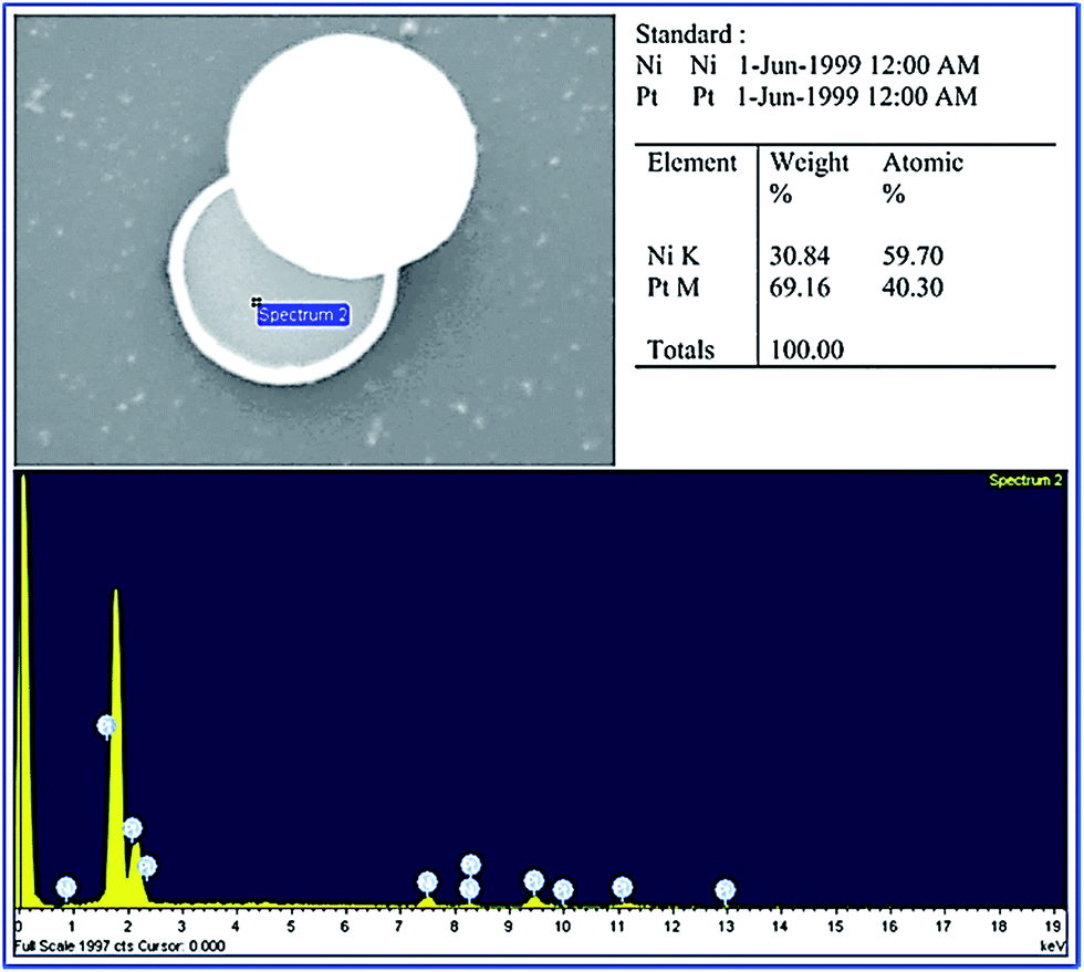
The microrockets are fabricated using a layer-by-layer deposition method based on the developed NEMS technology (see ESI†).11,12 The scanning electron microscopy (SEM) images of the fabricated microrockets are captured, as shown in Fig. 3. The inset shows the side view of one single enlarged microrocket. The material compositions of the eccentric nanoengine of the fabricated microrocket are confirmed via energy dispersive spectrometry (EDS) analysis, as shown in Fig. 4.
 |
| | Fig. 3 SEM images of the Pt–Ni–SU-8 microrocket with the eccentric nanoengine. The nanoengine of the microrocket is eccentrically located on one side of the rocket. The inlet shows the side view of one single enlarged microrocket. | |
 |
| | Fig. 4 EDS analysis results of the eccentric nanoengine of the fabricated Pt–Ni–SU-8 microrocket. The results show that the eccentric nanoengine contains two different metals: Ni and Pt, and the corresponding weight percentages are 30.84% and 69.16%. | |
O2 bubble generation
The fabricated Pt–Ni–SU-8 microrockets were immersed into diluted H2O2 solution to study the steerable motion (see ESI†). The generation and detachment of O2 bubbles associated with the motion of microrockets were characterized and captured by a camera installed onto an optical microscope. The results were recorded by a computer installed with a video recording software. It could be observed that the microrocket was stationary in DI water without the presence of H2O2, as shown in Fig. 5(a), and no O2 bubbles were generated. After the addition of H2O2 into DI water, the first O2 bubble was initially generated at the Pt-surface, as shown in Fig. 5(b). Thereafter, the generated O2 bubble grew bigger and bigger, as shown in Fig. 5(c). Finally, the first generated O2 bubble was detached from the microrocket and the next O2 bubble was growing, as shown in Fig. 5(d). The diameters of the detaching O2 bubbles from the microrocket immersed in 2 mol m−3 H2O2 solution were approximated to be 20 μm (Fig. 5(c)). The results were consistent with those reported by Wang and Wu.13
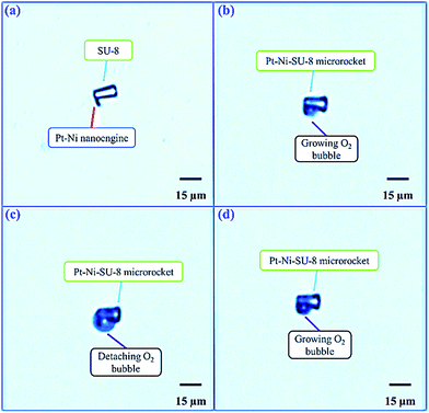 |
| | Fig. 5 The generation and detachment of O2 bubbles from the microrocket. (a) Pt–Ni–SU-8 microrocket was suspended in DI water without the presence of H2O2, no O2 bubbles were generated. (b) Pt–Ni–SU-8 microrocket was immersed in diluted H2O2 solution, the first O2 bubble was generated at the surface of the nanoengine; (c) the generated O2 bubble grew bigger and bigger; (d) the first generated O2 bubble with about 20 μm in diameter was detached from the microrocket and the next O2 bubble was generated and growing. | |
Characterization of the steerable propulsion of microrocket in H2O2 solution
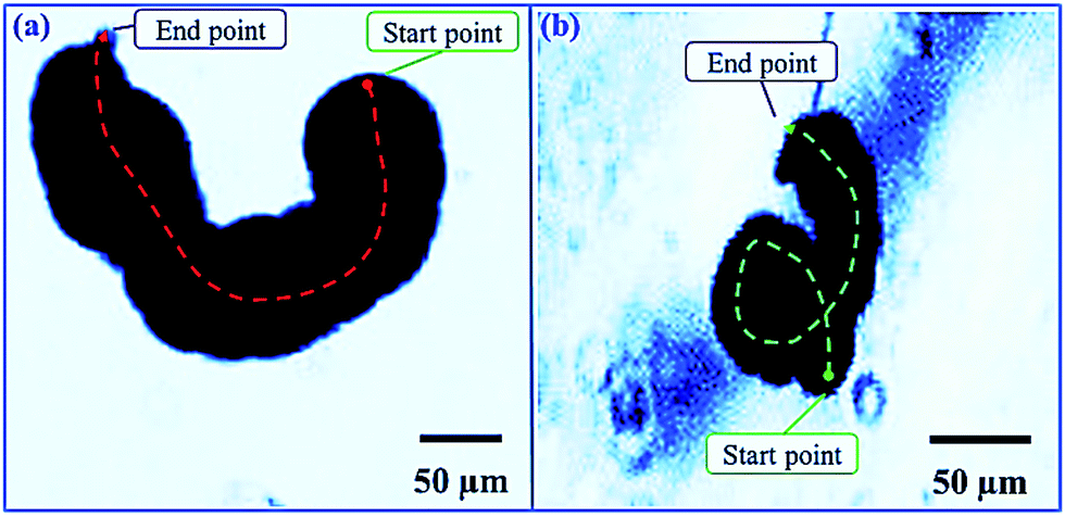
The fabricated microrockets with eccentric nanoengines were immersed into three different concentrated H2O2 solutions to investigate the steerable propulsion. The microrockets propelled forward circularly in either a clockwise or a counter-clockwise direction, as shown in Fig. 6. The time lapses of the steerable propulsion of the microrockets in 10 mol m−3 H2O2 solution are characterized, as depicted in Fig. 7. The corresponding circular trajectories of the microrockets are shown in Fig. 8.
 |
| | Fig. 6 Circular propulsion of Pt–Ni–SU-8 microrockets in H2O2 solution with three different concentrations. (a) and (b) Microrockets immersed in 10 mol m−3 H2O2 solution moved forward circularly in a clockwise and a counter-clockwise direction with a speed of 80 μm s−1, respectively. (c) The rocket suspended in 20 mol m−3 H2O2 solution propelled forward circularly in a counter-clockwise direction at a speed of 150 μm s−1. (d) The rocket immersed into 30 mol m−3 H2O2 solution moved forward circularly in a clockwise direction, the motion speed of the rocket was 200 μm s−1. | |
 |
| | Fig. 7 Time lapses of the circular propulsion of Pt–Ni–SU-8 microrockets in 10 mol m−3 H2O2 solution. (a) Time lapses of the motion of the rocket in a clockwise direction and (b) time lapses of the movement of the rocket in a counter-clockwise direction, respectively. | |
 |
| | Fig. 8 Trajectories of Pt–Ni–SU-8 microrockets in 10 mol m−3 H2O2 solution. (a) Trajectories (red dashed line) of the rocket propelling forward in a clockwise direction and (b) trajectories (green dashed line) of the microrocket moving forward in a counter-clockwise direction, respectively. | |
Results and discussion
In the experiments, the data demonstrated that H2O2 catalysed by Pt was decomposed into both O2 bubbles and H2O. The detachment of O2 bubbles from the eccentric nanoengine generated an off-center recoil force to thrust the microrocket propelling forward circularly.
Steerable propulsion speeds of microrocket in H2O2 solution
In the experiments, the Pt–Ni–SU-8 microrocket's steerable motion was investigated in H2O2 solution with three different concentrations. The lowest H2O2 concentration was 10 mol m−3 (Fig. 6(a) and (b)), the medium one was 20 mol m−3 (Fig. 6(c)) and the highest one was 30 mol m−3 (Fig. 6(d)). The elapsed time t (unit in s), as shown in Fig. 7, and the traversed distance L (unit in μm), as shown in Fig. 8, are obtained from the recorded videos. Thus, the speed v of microrockets can be calculated as
The corresponding speeds of the microrockets are calculated, which are about 80 (Fig. 6(a) and (b)), 150 (Fig. 6(c)) and 200 μm s−1 (Fig. 6(d)). In micro and nano realm, catalytic microrockets in DI water without the presence of the fuel H2O2 can undergo thermal fluctuation motion, called Brownian motion (see ESI†). In such a case, no O2 bubbles are generated (Fig. 5(a)), and microrockets move forward very slowly and randomly. As seen, the steerable propulsion speeds of Pt–Ni–SU-8 microrockets are much larger than Brownian motion speed.14 In general, the speeds of microrockets are increased with the increment of H2O2 concentration, in consistency with the theoretical derivation.15
Steerable propulsion of microrocket in H2O2 solution
The time lapses of the steerable motion of the microrockets in 10 mol m−3 H2O2 solution are further characterized, as depicted in Fig. 7. As can be seen, the microrockets are suspended in H2O2 solution, O2 bubbles are continuously generated from the eccentric Pt nanoengines, then are detached from the micro-rockets after a period of time. The off-center recoil force Fdrive, induced by the detachment of O2 bubbles, thrusts the microrockets to propel forward towards the SU-8 cylinders circularly in either a clockwise (Fig. 7(a)) or a counter-clockwise direction (Fig. 7(b)). The corresponding steerable trajectories of microrockets in 10 mol m−3 H2O2 solution, as shown in Fig. 8(a) and (b), are processed using “ImageJ” software.
Discussion on the steerable propulsion of microrocket
The material composition and the shapes of the fabricated microrockets are significantly different from those studied by other researchers,9,10,15 like the speeds of microrockets, which in our experiments are much lower than those (above 500 μm s−1) studied in ref. 9 and 10 or larger than those (below 10 μm s−1) reported by Gibbs et al.15 The differences observed may be caused by the size and shape of the particles, and the surface tension of the solution as proposed by Gibbs et al.15 giving us the guidance how to design and investigate the microrockets in future.
In addition, microrockets with eccentric nanoengines can move forward circularly in either a clockwise direction or a counter-clockwise direction, as shown in Fig. 6. The nanoengines are located on one side of the microrockets, thus O2 bubbles are only generated at the surface of the eccentric nanoengines and detached from the rockets, resulting in the generated recoil force Fdrive is off-center and not aligned with the drag force Fdrag, which in turn introduces a torque Q, as shown in Fig. 9, which further leads to microrockets propelling forward circularly with a radius Rc. At steady state, if the eccentric nanoengines are located on the left-hand side of the rockets, the rockets will move forward circularly in a clockwise direction, as shown in Fig. 9(a). In contrast, the rockets propel forward circularly in a counter-clockwise direction, due to the nanoengines are located on the right-hand side of the rockets, as shown in Fig. 9(a). The experimental results are in good agreement with our theoretical analysis, thus our model and theory are verified.
 |
| | Fig. 9 Schematic diagrams for explaining the circularly steerable propulsion of Pt–Ni–SU-8 microrockets with eccentric nanoengines. (a) Pt–Ni–SU-8 microrocket can move forward towards the SU-8 cylinder circularly in a clockwise direction. O2 bubbles generated at the Pt nanoengine are detached from the left-hand side of the rocket. (b) Diagram of the explanation of the circular motion of the Pt–Ni–SU-8 microrocket in a counter-clockwise direction, O2 bubbles generated at the Pt nanoengine are located at the right-hand side of the rocket. | |
Conclusions
A circularly steerable propulsion mechanism was proposed for the first time to investigate the steerable movement of Pt–Ni–SU-8 microrocket with an eccentric nanoengine in H2O2 solution. The microrocket was fabricated by a high-efficiency layer-by-layer deposition method based on the NEMS technology. The steerable movement of the microrocket was experimentally characterized in three different concentrated H2O2 solutions. The steerable propulsion was proved to be induced by the detachment of the off-center O2 bubbles from the surface of the eccentric Pt nanoengine. The speeds of the microrocket were increased with the increment of the concentration of the fuel H2O2. Microrockets were able to self-steer and propel forward circularly in either a clockwise or a counter-clockwise direction. The results of this research will enhance the exploration on the steerable propulsion of the microrocket via the design of the Pt-nanoengine.12,16 Further investigations can be conducted, including the propulsion characterization of the microrocket placed in micro-channels17 and the motion controlling using external magnetic field.18,19 Such microrocket may be useful for environmental remediation20 and other applications.21,22 In special, H2O2, belongs to the class of reactive oxygen species (ROS) like O2−, HO˙, H2O2, RSSR˙−, RS˙ or RSOO˙, and is well recognized for playing a dual role as both deleterious and beneficial species in biological cells. Sustaining the balance of ROS, called, redox homeostasis (RH) is crucial for every organism in order to effectively harness the reducing power through catabolism of various substrates and to utilize this power in the anabolism of cellular components such as DNA, lipids, and proteins. Imbalance of ROS is implicated in aging, cancer, cardiovascular diseases, diabetes and neurodegeneration.23 Among biologically relevant ROS, H2O2 has the highest intracellular concentration (mol). Therefore, the high efficiency of SU-8 microrockets forms a novel platform to sense excess of intracellular concentrations of H2O2 in living cells.
Acknowledgements
We greatly acknowledge the fund from Ministry of Education Tier 2 (MOE2011-T2-2-156; ARC 18/12), Singapore to support this research work. We also gratefully thank Mr Pek and Mr Nordin for their kind help on the fabrication and SEM characterization of microrockets.
Notes and references
- D. Stock, K. Namba and L. K. Lee, Curr. Opin. Biotechnol., 2012, 23, 545 CrossRef CAS PubMed.
- G. Grüber, M. S. Manimekalai, F. Mayer and V. Müller, Biochim. Biophys. Acta, Bioenerg., 2014, 1837, 940 CrossRef PubMed.
- S. Sanchez, A. Solovev, S. Harazim, C. Deneke, Y. Mei and O. Schmidt, Chem. Rec., 2011, 11, 367 CrossRef CAS PubMed.
- G. Zhao, A. Ambrosi and M. Pumera, Nanoscale, 2013, 5, 1319 RSC.
- W. Z. Teo, H. Wang and M. Pumera, Chem. Commun., 2016, 52, 4333 RSC.
- W. Gao, A. Uygun and J. Wang, J. Am. Chem. Soc., 2012, 134, 897 CrossRef CAS PubMed.
- L. X. Hu, J. M. Miao and G. Grüber, Sens. Actuators, B, 2017, 239, 586 CrossRef CAS.
- S. B. Hall, E. A. Khudaish and A. L. Hart, Electrochim. Acta, 1998, 43, 579 CrossRef CAS.
- J. Li, Q. Xiao, J. Z. Jiang, G. N. Chena and J. J. Sun, RSC Adv., 2014, 4, 27522 RSC.
- M. Safdar, T. Itkonen and J. Janis, RSC Adv., 2015, 5, 13171 RSC.
- K. Tao, S. W. Lye, J. M. Miao, L. H. Tang and X. Hu, J. Micromech. Microeng., 2015, 25, 104014 CrossRef.
- L. X. Hu, J. M. Miao and G. Grüber, RSC Adv., 2016, 6, 3399 RSC.
- S. Wang and N. Wu, Langmuir, 2014, 30, 3477 CrossRef CAS PubMed.
- T. Mirkovic, N. S. Zacharia, G. D. Scholes and G. A. Ozin, Small, 2010, 6, 159 CrossRef CAS PubMed.
- J. G. Gibbs and Y. P. Zhao, Appl. Phys. Lett., 2009, 94, 163104 CrossRef.
- J. Li, G. Huang, M. Ye, M. Li, R. Liu and Y. Mei, Nanoscale, 2011, 3, 5083 RSC.
- L. Soler, C. Martínez-Cisneros, A. Swiersy, S. Sánchez and O. Schmidt, Lab Chip, 2013, 13, 4299 RSC.
- T. R. Kline, W. F. Paxton, T. E. Mallouk and A. Sen, Angew. Chem., Int. Ed., 2005, 44, 744 CrossRef CAS PubMed.
- G. A. Ozin, ChemCatChem, 2013, 5, 2798 CrossRef CAS.
- T. Li, L. Li, W. Song, L. Wang, G. Shao and G. Zhang, ECS J. Solid State Sci. Technol., 2015, 4, S3016 CrossRef CAS.
- D. A. Wilson, R. J. M. Nolte and J. C. M. Hest, Nat. Chem., 2012, 4, 268 CrossRef CAS PubMed.
- W. Gao, R. F. Dong, S. Thamphiwatana, J. X. Li, W. W. Gao, L. F. Zhang and J. Wang, ACS Nano, 2015, 9, 117 CrossRef CAS PubMed.
- M. Giorgio, M. Trinei, E. Migliaccio and P. G. Pelicii, Nat. Rev. Mol. Cell Biol., 2007, 8, 722 CrossRef CAS PubMed.
Footnote |
| † Electronic supplementary information (ESI) available: The equipment, materials, and software used; the derivation of driving force, fabrication details, experimental set-up, and Brownian motion speed of Pt–Ni–SU-8 microrocket with an eccentric nanoengine. See DOI: 10.1039/c6ra17248b |
|
| This journal is © The Royal Society of Chemistry 2016 |
Click here to see how this site uses Cookies. View our privacy policy here.