A review on non-electro nanofibre spinning techniques
Elena Stojanovska
,
Emine Canbay
,
Esra Serife Pampal,
Mehmet D. Calisir
,
Onur Agma,
Yusuf Polat
,
Ramazan Simsek,
N. A. Serhat Gundogdu,
Yasin Akgul and
Ali Kilic
 *
*
TEMAG LABS, Istanbul Technical University, 34437 Taksim, Istanbul, Turkey. E-mail: alikilic@itu.edu.tr
First published on 17th August 2016
Abstract
A large surface area, scalable porosity, and versatility have made nanofibres one of the most widely investigated morphologies among the nanomaterials. The characteristic properties of nanofibres have made them useful in a broad range of applications, such as filters, membranes, tissue engineering, wound dressings, protective clothing, reinforcement in composite materials, and sensors. So far, various top-down and bottom-up approaches were proposed to produce nanofibres. In this paper, a comprehensive review is presented on non-electro fiber spinning techniques, along with their mechanisms. The parameters of these techniques are also discussed in detail, while process-specific gains were emphasized according to the end uses. This review paper also provides a literature insight into the biomedical, filtration, optical, and energy applications of nanofibres produced via the most typical and widely used methods.
1. Introduction
Based on an electrohydrodynamic atomization procedure, electrospinning is by far the most widely investigated nanofibre production technique since the 2000s. Being appropriate for a large variety of materials, it offers the possibility to obtain fibers down to several nanometers in diameter; this and feasibility for commercial production are the main advantages of electrospinning. However, limitations, such as safety problems, low production rates, and high dependency on polymer properties, were claimed in several studies. Hence, several non-electrospinning techniques were developed to improve production. Some of these techniques include solution blowing (or air-jet spinning), drawing techniques, template synthesis, centrifugal spinning, phase inversion/separation, freeze/drying synthesis, the spinneret-based tunable engineered parameters (STEP) method, interfacial polymerization of nanofibres, self-assembly, and splitting. Among these, solution blowing and centrifugal spinning might be seen as the most advantageous from the aspect of industrialization and scalability; however, for some polymers, material-based parameters can dictate other methods, such as template synthesis, phase inversion/separation, and freeze/drying synthesis.2. Solution blowing or air-jet spinning
Solution blowing is one of the most feasible non-electro nanofibre production techniques where compressed air is used as the driving fiber formation force.1 The most widely used model is a concentric nozzle system (Fig. 1), where polymer solution is pumped into the inner nozzle and high-pressure gas is delivered through the outer nozzle simultaneously. The polymer solution leaves the nozzle as multiple strands under the stretching forces from the surrounding high-speed gas. High shear forces at the gas/solution interface result in evaporation of solvent and attenuation of the blown jet. The solidified jets are further collected on a collector surface as a nonwoven web of nanofibers.2,3 A general schematic of solution blowing is displayed in Fig. 1, where high-speed gas surrounding the polymeric liquid jet attenuates it to form a solid nanofibre.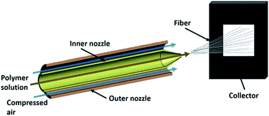 | ||
| Fig. 1 Schematic presentation of solution-blowing system. Reproduced, with permission, from ref. 1, copyright 2015, John Wiley and Sons. | ||
2.1. General mechanism
At the end of the straight part, the cross sectional area of the jet is still big enough to resist the bending effect. Both Newtonian and non-Newtonian approaches can be used to explain the movement of liquid jets.4 The two parts of the liquid jets, namely, the straight part and the perturbed part, are shown in Fig. 2.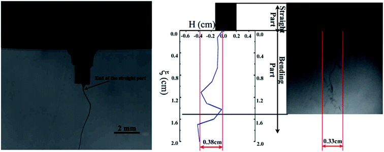 | ||
| Fig. 2 Straight and perturbed parts of the liquid jet. Reproduced, with permission, from ref. 4, copyright 2015, Elsevier. | ||
The physical mechanism of nanofibre production via solution blowing was studied by Sinha-Ray et al.4 In this study, researchers reported that the solution blowing was assumed to be an isothermal process. Eqn (1) gives the decrease in mass per unit length in the straight part.5
 | (1) |
In this equation, x is the axial coordinate of the straight jet axis; f is the cross-sectional area of the liquid jet; a is the radius of the jet and the jet is assumed to have a circular shape; V is the jet velocity at the x axis; hm is the mass transfer coefficient; Cs,eq(T) and Cs,∞ are the solvent vapor volume fractions at the jet surface and far away, respectively, and T is the temperature.5
According to Yarin et al.,5 hm is described by the following equation;
 | (2) |
The balance for the momentum of the liquid jet is given in eqn (3) for the straight part.
 | (3) |
 | (4) |
2.2. Parameters of solution blowing
Up to now, several attempts have been made by researchers to determine the parameters governing the solution-blowing methods. The attenuation of the polymer jet is affected by bending instability, stretching, flapping motion and the evaporation rate of the solvent.6 The polymer type and concentration also have an effect on the fiber morphology. Additionally, the solution injection rate, the gas flow pressure, the distance from the nozzle to the collector, and the protrusion length of the inner nozzle are some other important parameters in this technique.2 Table 1 summarizes the main parameters that affect the fiber formation process when using the solution-blowing technique.| Solution parameters | Viscosity |
| Polymer concentration | |
| Molecular weight | |
| Surface tension | |
| Vapour pressure | |
| Process parameters | Air pressure |
| Nozzle collector distance | |
| Solution flow-rate | |
| System parameters | Nozzle diameter |
| Nozzle geometry | |
| Ambient | Temperature |
| Humidity | |
| Atmospheric pressure |
Medeiros et al.2 studied the effect of different polymer types (polylactic acid (PLA), poly(methyl methacrylate) (PMMA), polystyrene (PS), and polyaniline (PAni)), their concentration, the working distance, the protrusion length of the inner nozzle, and the injection rate on fiber thickness and morphology, by using the nozzle system, shown in Fig. 3. They reported that, if there is no gas flow, the pumped solution forms a convex-shaped droplet at the orifice of the inner nozzle and drops. But, after the gas inlet, a low-pressure regime (P2) is produced, which results in solution acceleration, even there is no pumping. Additionally, the high-velocity gas stream and shearing effect at the gas/polymer interface causes the solution to change from a convex to a conical shape at this region. When these forces are higher than the surface tension of the solution, jet formation towards the collector is observed and, while travelling the distance between the nozzle and the collector, solvent evaporates and polymer fibers are collected on the collector.
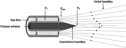 | ||
| Fig. 3 Concentric nozzle design for solution-blowing method and gas-pressure regions: P1 high-pressure gas flow, P2 low-pressure regime due to gas flow. Reproduced, with permission, from ref. 2, copyright 2009, John Wiley and Sons. | ||
The same group also made a comparison between nanofibrous mats obtained from solution blowing and electrospinning methods. According to their results, both methods give similar nano-microfibers from the same polymer solution (10 wt% concentration). They emphasized the solution feeding rate as a large difference between the two methods; with solution blowing, the rate is one order of magnitude higher than that with electrospinning, which means a higher production efficiency. Additionally, the optimum ratio between the gas flow pressure and the solution feeding rate, and the working distance for the solvent to evaporate and form solidified fibers on the collector were also major factors, otherwise film formation takes place. The protrusion length of the nozzle should also be between zero and 3 mm, otherwise the orifice of the nozzle becomes blocked and causes discontinuity in the production. Moreover, no direct relation was found between the fiber diameter and individual process parameters, such as gas pressure, feeding rate, working distance and protrusion length of the nozzle, with the exception of polymer types and their concentration. An increasing concentration causes thicker fiber formation for all type of polymers, which can be attributed to the different surface tensions of these polymer solutions. Moreover, X. P. Zhuang et al.3 produced submicron-scale cellulose fibers via solution blowing and investigated the effect of the air temperature in the spinning line on solvent evaporation and fiber formation. They realized that increasing the temperature reduces the number of finer fibers due to faster evaporation, which suppresses the attenuation of blown streams.
2.3. Solution-blown nanofibre applications
Solution blowing is independent of electrostatic constraints and solvent limitations due to the dielectric constant, and it can be applicable to any voltage-sensitive polymers.2–4 These characteristics ultimately extended its applications from energy to filtration products.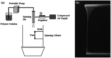 | ||
| Fig. 4 (a) Schematic of the aligned nanofibre production, (b) digital image of the aligned nanofibre yarn. Reproduced, with permission, from ref. 11, copyright 2013, Springer. | ||
Solution-blown zinc oxide nano-flakes encapsulated into carbon nanofibres were also reported as an electrode for supercapacitors. These electrodes gave a capacitance of 212 F g−1 and an extremely good cycle performance, with only 5.41% capacitance lost.13 Beside these, CNFs obtained by solution blowing of PAN were reported as electrodes for microbial fuel cells. This CNF mat showed a current density of 17 A m−2, which with the addition of carbon black, increased to 21 A m−2.14
Moreover, in clinical applications, for providing support to bone growth, nHA/PLA composite nanofibre mats were also produced via solution blowing, in order to overcome the disadvantages of nano-hydroxyapatite [nHA; Ca10(PO4)6(OH)2], such as brittleness, low resistance to impact, and limited drug loading times.22 Additionally, nHA/PLA showed more significant cell ingrowth and reproduction than plain PLA after biological tests with in vitro cell cultures of MC3T3-E1 osteoblast-like cells formed on the nanofibrous mats.22 Researchers also developed PLA/polyvinylpyrrolidone (PVP) containing copaiba oil composite nanofibres by solution blowing, in order to utilize the antimicrobial activity of copaiba oil, containing β-caryophyllene, as antimicrobial constituent; this was proven by gas chromatography and in vitro testing.23 Poly(2-dimethylamino-ethyl methacrylate) (PDMAEMA) powder shows antimicrobial activity and was also used as a nonwoven nanofibre mat, produced by solution blowing. Research studies were also carried out to determine the antimicrobial activity of PDMAEMA nonwoven nanofibres with 10 μm average diameter and 8.56% minimum bactericidal concentrations against Gram-positive (Staphylococcus aureus) and Gram-negative (Escherichia coli) bacteria and diploid fungi (Candida albicans).24 In another interesting work, electrospun and solution-blown nanofibrous mats containing antimicrobial agents were combined, such as soy protein, solution-blown nanofibres with Ag, and nylon 6 electrospun nanofibres doped with TiO2 nanoparticles. Due to the biocompatible properties of these nanofibres, they can be used as bandages for wound healing.25
In another study, solution-blown nanofibres of various biopolymers, such as soy protein, cellulose acetate, lignin, zein, sericin, and bovine serum albumin (BSA), were produced and mixed with synthetic polymers, such as nylon 6 or polyethylene terephthalate (PET), in order to improve their mechanical properties. The combination of biopolymer nanofibres and PET has been extensively used in cardiovascular surgery for blood vessels, artificial heart valves, and artificial heart implantations. In addition, BSA and polyvinyl alcohol (PVA), as biodegradable and biocompatible polymers, were mixed and converted into nanofibres by solution blowing, and are used in wound dressings for drug delivery.26 Currently, airbrush nanofibre production is being used commercially for a variety of polymers, as shown in Fig. 5.
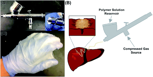 | ||
| Fig. 5 (A) Commercial airbrush nanofibre production (B) schematic representation of application procedure of airbrush (C) protective nanofibre coating on glove. Reproduced, with permission, from ref. 27, copyright 2014, American Chemical Society. | ||
PLGA (poly(lactic-co-glycolic acid)) polymers, having superior biocompatibility and biodegradability, are widely used in biomedical applications. They are converted into nanofibres through solution blowing and were first tested on a single piglet, for lung resection, intestinal anastomosis, and superficial liver and diaphragmatic injury. PLGA deposition causes liver bleeding and lung surface segmentectomy (Fig. 6), which provokes destruction of the nanofibre layer in less than 1 min.27
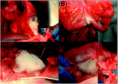 | ||
| Fig. 6 Coating of PLGA nanofibres on piglet organs: (A) lung resection; (B) intestinal anastomosis; (C) liver injury; (D) diaphragmatic hernia. Reproduced, with permission, from ref. 27, copyright 2014, American Chemical Society. | ||
Moreover, for use in textile applications, super-oleophobic surfaces were produced via solution blowing of poly(methyl methacrylate) nanofibres.28
3. Centrifugal spinning
Centrifugal spinning is another alternative nanofibre formation technique that can overcome some of the disadvantages of electrospinning, such as its low production rate and high voltage necessity for industrial applications. It is regarded as the most promising, due to its fast production rate, cost effectiveness and production safety. Nanofibres are produced by centrifugal forces, imitating the cotton-candy production principle. A schematic of a centrifugal spinning device is given in Fig. 7. In general terms, a polymer solution or melt is fed from a syringe pump or an extruder into a rotating chamber, consisting of two or more orifices. During the course of rotation, the centrifugal force pushes the polymer solution/melt towards the inner surfaces of the chamber, guiding it towards the orifices. When the centrifugal force exceeds the surface tension and the viscosity of the solution or melt, the polymer jet exits from the orifices. Then, the jet elongates and the solution evaporates until it reaches the collector plane.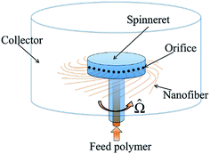 | ||
| Fig. 7 Schematic of centrifugal spinning device. Reproduced, with permission, from ref. 31, copyright 2014, American Physical Society. | ||
3.1. General mechanism
The centrifugal force (Fc) depends on the angular speed (ω) of the chamber, the polymer mass (m) inside it and the chamber radius (R) [eqn (5)]. When the angular velocity reaches a critical value, the droplet starts to extend. When this critical value is achieved, the jet leaves the orifice with a curved trajectory.32,33| Fc = mω2Rs | (5) |
There are two different chamber designs proposed: a chamber with nozzles and a nozzleless rotating disk. Unlike the oriented polymer output when nozzles are present, in the nozzleless system, the uniform liquid polymer spreads on a disk and divides into fingers because of Rayleigh–Taylor instability. Xu et al. show the nozzle and nozzleless systems in their study [Fig. 8].33
 | ||
| Fig. 8 The evolution of jet initiation for (a)–(e) nozzle-centrifugal spinning, and (f)–(j) nozzleless centrifugal spinning. Reproduced, with permission, from ref. 33, copyright 2014, John Wiley and Sons. | ||
Xu et al. determined the critical angular velocity for nozzle and nozzleless systems separately, according to the balance of centrifugal force, viscous force, and surface tension. Besides, they also investigated the initial jet velocities of both systems by means of critical angular velocities. By changing the jet velocity and the concentration of the polymer solution, the rotation speed of the chamber can be adjusted for different solutions. After the jet exit, the nozzle and nozzleless systems have similar motion. The necking, the whipping of the jet and the anti-S shape occurred in both of these systems.33
Researchers also classified the solution-spun fiber formation process by centrifugal spinning into three main stages, which were jet initiation, jet extension/elongation, and solvent evaporation/fiber formation.34–36
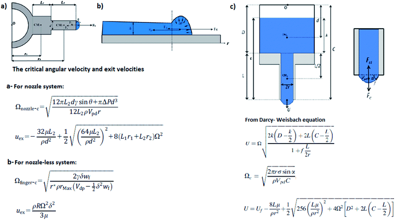 | ||
| Fig. 9 The critical angular velocities and jet exit velocities according to different models (a) nozzle system model and (b) nozzleless system model. Reproduced, with permission, from ref. 33, copyright 2014, John Wiley and Sons. (c) Nozzle system model. Reproduced, with permission, from ref. 32, copyright 2013, AIP Publishing LLC. | ||
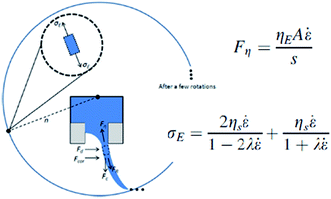 | ||
| Fig. 10 Forces and extensional stress on fiber during stretching. Reproduced, with permission, from ref. 33, copyright 2013, AIP Publishing LLC. | ||
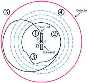 | ||
| Fig. 11 Fiber formation process; (1) fiber formation, (2) orbital trajectory, (3) fiber vibration, (4) orbital expansion, and (5) collection. Reproduced, with permission, from ref. 32, copyright 2013, AIP Publishing LLC. | ||
According to Mellado et al., these three stages are characterized by different scales. The ejection time scale is inversely proportional to the critical angular velocity, Ωth, at which the jet is initiated from the orifice, τ1 ∼ 1/Ωth. Then, the jet is elongated in the viscous time scale, τ2 ∼ r2ρ/μ, where μ is the extensional viscosity and ρ is the density. After that, the solvent evaporation time scale controls the internal diffusion of the solvent through the drying polymer, τ2 ∼ r2/D, where D is the diffusion coefficient of the solvent and r is the jet radius. And the extension and evaporation stages can be separated by the ratio τ2/τ3 ∼ 10−2.35
3.2. Parameters on centrifugal spinning process
As explained in the previous section, there are several parameters that affect centrifugal spinning. Among them, the angular velocity of the chamber, the orifice radius, the viscoelasticity, the concentration of the solution, the surface tension, the evaporation rate for solution applications, the temperature for melt-spun applications, and the distance from the orifice to the collector might be counted as the dominating ones.32 For the jet formation, the centrifugal forces must be high to overcome the surface tension of the solution or melt. However, these forces should not be too high in order to prevent the jet from breaking and/or bead formation. These undesired formations may also occur when a low angular velocity is applied and/or when a low-viscosity polymer solution is used.32 When the viscosity is high enough, the centrifugal forces may not be strong enough for jet formation, thus the polymer cannot be stretched. On the other hand, when the viscosity is too low, the jet breaks up and beads are formed. The concentration of the polymer solution affects the process in the same way, since it is related to its viscosity. The total polymer concentration has to exceed the critical value for obtaining adequate chain entanglement. This is necessary for uniform continuous fiber formation.34 The evaporation rate is also significant for spinning of polymer solutions. As the jet is driven from the orifice to the collector, the solvent evaporates, affecting the fiber diameters. When the evaporation rate is low, the solvent cannot evaporate completely and the fibers are collected as a thin film on the collector. On the other hand, the elongation process of the jet is suppressed and the fiber diameter increases if the evaporation rate is high. The temperature is also crucial when spinning melt polymers; when the temperature is too high, the polymer is corrupted or burned; on the contrary, if it is too low, jet formation becomes difficult and the fiber diameters increase or the jet cannot be formed.32Moreover, there are several dimensionless numbers in polymer rheology that play an important role in the centrifugal spinning mechanism and can be used to determine the final diameter of fibers. Those include the Weissenberg number (Wi), Reynolds number (Re), and the capillary number (Ca), which characterizes the thinning of filaments.36,37 Ren et al. state that if there is no external action of thinning (called self-thinning), these three numbers will be zero. In such circumstances, other dimensionless numbers that describe material properties influence the spinning process. These numbers include the Ohnesorge number (Oh), the Deborah number (De), the elastocapillary number (Ec), and the elasticity number (El). Oh, De, and Ec can be defined as the ratio between viscous and Rayleigh time scales. In the self-thinning process, capillary break-up is a result of surface tension and this break-up slows down due to inertia and viscous stresses. When the inertia is negligible, break-up happens during the viscous time. When the viscous stresses are negligible, the break-up happens during the Rayleigh time. If the viscous time scale is larger than the Rayleigh time scale, the inertia is not significant. Otherwise, the viscosity is not significant. In many cases where fiber formation occurs, the Oh and Ec numbers are high.36
The characteristic velocity (Ucent) and time (tcent) scales are also important to quantify the thinning dynamics in the centrifugal spinning process. The time scales in the self-thinning process are compared with the centrifugal time scale (tcent) for quantifying thinning. The number is identified by comparison with the Rayleigh time ((We)1/2 = tR/tcent). If the characteristic time is compared with the viscous time, the Ca number is identified as the ratio of viscous forces and surface tension (Ca = tviscous/tcent). If it is compared with the relaxation time, the Wi number is identified (Wi = λ/tcent). These numbers are proportional to the rotational speed.36
Padron et al. also investigated the effects of different orifice orientations on fiber trajectories and their diameters by using needles as nozzles for 6 wt% PEO (polyethylene oxide) at 6000 rpm. They studied various orifices with different exit angles (the direction of rotation, 89°, 30°; the opposite direction of rotation, 30°, 89°, and straight (0°)), in order to find the optimal jet exit angle and minimum average fiber diameter. The results indicated that the lowest average fiber diameters with the lowest standard deviation are observed with straight needles and, besides this, needles curved in a direction of 89° displayed the largest outward trajectory; the opposite system with 89° had the largest inward trajectory. They also stated that a smaller orifice diameter gives fibers with a reduced diameter and a reduced amount of beads.32
3.3. Applications of centrifugally spun nanofibres
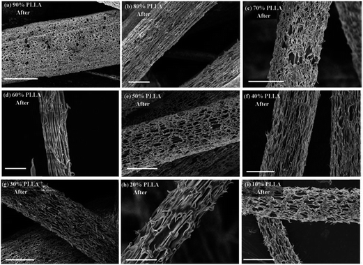 | ||
| Fig. 12 Rough and porous surfaces of PLLA nanofibres after PVP etched away (a) 90% PLLA; (b) 80% PLLA; (c) 70% PLLA; (d) 60% PLLA; (e) 50% PLLA; (f) 40% PLLA; (g) 30% PLLA; (h) 20% PLLA; (i) 10% PLLA (scale bar: 1 μm). Reproduced, with permission, from ref. 49, copyright 2013, Royal Society of Chemistry. | ||
Research was also carried out to investigate the drug-release behavior and antimicrobial activity of centrifugally spun drug-loaded PVP/PCL nanofibres. Samples showed antibacterial efficiency on both Gram-positive (S. epidermis and B. megaterium) and Gram-negative (E. coli and P. aeruginosa) bacteria, which can be found in dermal infections, along with better drug-release behavior. These results show that nanofibrous webs formed by centrifugal spinning can also find application in wound dressing.50 In another study by L. A. Mary and coworkers, PVP/PCL nanofibres were fabricated and their drug-release behavior was investigated. The nanofibre mats were loaded with natural extract and cell culture studies were made. Cell culture studies show that C-spun webs are biocompatible and can be used for guided tissue regeneration, which is critical in tissue engineering.51 Furthermore, Sebe et al. investigated the antimicrobial activity of PVP/iodine nanofibres formed via centrifugal spinning. They showed that the addition of iodine decreased the mechanical strength of fibers, while increasing their antibacterial efficiency.52 The C-spinning system can also be successfully applied for the preparation of polymer/biocide-containing composite fibers with a potential for wound dressing applications.52 The C-spinning system can be combined with several methods, such as electrophoretic deposition, where highly aligned fibrous networks are required for biomedical applications.53,54
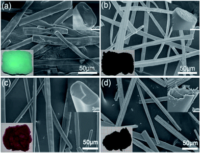 | ||
| Fig. 13 SEM images of (a) NiO and (c) Co3O4 precursor fibers obtained by centrifugal spinning and (b), (d) their oxidized versions. The insets on the left lower corner show the corresponding real samples, while the insets on the right upper corner correspond to their cross sections. Reproduced, with permission, from ref. 61, copyright 2016, Elsevier. | ||
The centrifugal spinning method can also be applied for large-scale nanofibre production of ceramic nanofibres, such as hematite (Fe2O3)65 or barium titanate (BaTiO3).57 Fe2O3/poly(ethylene oxide) (PEO) solutions have also been converted into nanofibre mats containing fibers with diameters between 200 nm and 1.4 μm after calcination, which are found to be promising materials for fluid filters. BaTiO3 nanofibres with a diameter of almost 100 nm, obtained after calcination of centrifugally spun BaTiO3/polyvinylpyrrolidone (PVP) nanofibres at 9000 rpm, possess a perovskite structure and ferroelectric memory, making them suitable for various engineering applications.
Centrifugal spinning allows the formation of a rough surface of firmly wrapped indium tin oxide (ITO) nanofibres over optical fibers.56 Electric-field-assisted centrifugal spinning has been used in order to collect nanofibres on specific substrate-optical fibers. Spinning ITO/PVP solution and using optical fibers as a collection area over 8 min gives an ITO coating of 2.7 μm, which transmits green light with lower brightness when applied as an LED. The combination of centrifugal and electric forces allows the formation of crossbar arrays containing layers with fibers aligned at specific angles, or twisted microropes.66 These interesting structures exhibit fluorescent properties when a proper amount of fluorescent tracer is added into the polymer solution.
The versatility of centrifugal devices has recently been demonstrated by using them for simultaneous polymerization and fiber extrusion.67 Connecting the spinning head with an electric field allowed electro-polymerization of PANi on TiO2 nanotubes and extrusion of the polymer into fibers with thermoelectric properties, which are suitable for application in thermoelectric energy conversion.
4. Template synthesis
Template synthesis is a molding-like method for producing nanomaterials from a wide range of organic68 and inorganic69 materials. It is a convenient method for the synthesis of fibrous materials (including fibers, tubes, rods, and fibrils) with controlled morphology, narrow diameter, and high flexibility in an aligned fashion (either horizontally or vertically), but with a much shorter length compared to the fibers obtained by conventional spinning methods. Fibrous structures can be molded using hard or soft templates.70 The basic concept of synthesis is shown in Fig. 14. In the former case, hard membrane matrices with nano-scale pores, usually made of polycarbonate and alumina, are used as templates. Polymeric solutions68 or melts71 may also be driven by vacuum pressure or capillary action of the polymer.68 The electrostatic forces can also be used for deposition of the polymer solutions68 or melts71 into the template membrane, usually referred as electrochemical template synthesis, in which a monomeric solution polymerizes into the pores of the membrane attached on the electrode surface.72 Vapor phases are another alternative for polymer deposition into hard templates previously covered with oxidizing agent.73 However, the major drawback is the complete removal of the template, without damaging the fibrous structure of the nanomaterial, by dissolving the template or by polishing them with a scalpel. Currently, more precise removal of the template can be achieved by using block-copolymers as hard templates, through double etching.74 Another drawback is the preparation of single-use templates, despite the variety of shapes and sizes that can be achieved. Soft template synthesis is the other type of template synthesis, where soft intermediates, such as liquid crystals (LC)75 or surfactants,76 are used for the orientation of polymeric and/or non-polymeric molecules into ordered structures in specific dimensions and shapes. The addition of surfactants promotes the fibrous structures over aggregated polymeric particles.77 Modification of the nanostructure architecture can be achieved by altering the amount and type of surfactant and oxidizing agent. Inorganic fibrous structures can be synthesized by adding dissolved LC into the main solution. Further treating it at elevated temperatures78 or in supercritical CO2 equipment,79 or adding oxidizing agent,80 allows separation of the fibrous precipitate. Organic LC-assisted nanofibres can be obtained by the extrusion of polymerizable lyotropic LC solution and subsequent photo-polymerization.81 Surfactants also help in organizing inorganic molecules into fiber structures, which can further be covered with a carbon layer by chemical vapour deposition.82 Nanofibres from insoluble polymers can be polymerized by a seeding method, where organic, biological, or inorganic nanofibres are used as seeds.83–85 Dispersion of these seeds, containing oxidizing agent, serves as templates, on which polymer is grown in a specific fiber-like shape. Their sizes can be controlled with the amount of the seed compound (either organic or inorganic), or the concentration of the oxidizing agent.86,87 An alternative faster approach is electrochemical polymer growth on metallic arrays.88 The nanofibre morphology (smooth, branched) in this method is controlled by altering the electrodeposition time. Furthermore, these organometallic nanofibres can be converted into doped carbon nanofibres.89 Conventionally-spun polymer nanofibres can also serve as templates for organic, inorganic or porous carbon nanofibre formation. Composite nanofibres can also be produced by using spun nanofibres as a template for in situ deposition of other polymers in the presence of oxidizing agent.90 Another alternative is removing the organic part by annealing of electrospun polymeric fiber containing inorganic salts.91,92 Polymeric electrospun nanofibres containing inorganic particles can be converted into porous carbon nanofibres after a leaching process, which removes the inorganic part of the carbonized fibers.93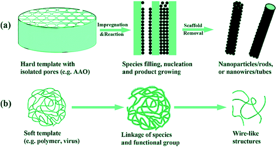 | ||
| Fig. 14 Schematic description of (a) hard and (b) soft template synthesis of nanofibrous structures. Reproduced, with permission, from ref. 69, copyright 2008, American Chemical Society. | ||
The template synthesis is especially convenient for synthesis of polymer nanofibres with well-controlled electron conductivity and luminescence, which can be used in electronics, optoelectronics, chemical or gas sensors, and batteries.74,79,82,94
5. Phase inversion
Phase inversion is another strategy that enables the formation of nanofibrous membranes. Freezing the polymer solution, followed by solvent removal by exchanging it with another one, and drying the fibrous foam-like structure is the general route of the phase-inversion technique. The freezing step has the role of phase separation and is thermally induced, and can be varied with temperature gradients by freezing a polymer solution into multi-material pots, resulting in micro-tubular structures oriented in different directions.95 Additionally, the structure can be adjusted by using a mixture of solvents, by changing the polymer concentration or by modifying the phase-separation temperature.The freeze-drying fiber-formation technique, also known as ice-segregation-induced self-assembly96 or solid–liquid phase separation,97 involves freezing a very dilute polymer solution and keeping it under reduced pressure. The reduced temperature allows the growth of ice-crystals and nucleation, while the reduced pressure allows direct sublimation of the water without any chemical reaction or side products. The fibrous structures obtained from solutions with concentrations lower than 0.1 wt%, have fibers with diameters of 100 nm.98 Increasing the polymer concentration in the solution does not allow aggregation of large ice crystals and thus gives porous non-fibrous structures.96 Controlling the rate at which the solution is submerged into freezing conditions allows control over the alignment of the fibers into the structure. Such control can be achieved by freezing the solution vessel gradually at a constant rate,99 or extruding the polymer solution from a spinneret on a frozen rotating drum.100 However, for water-soluble polymers, sublimation of the solvent is possible under specific conditions, characterized by low temperatures and pressures.
Phase-inversion-produced membranes provide cell growth, proliferation and differentiation for use as tissues for artificial organs,101 neuronal networks,102 bioreactors,103 or cell sources.104 Inorganic fibers for photovoltaic cells can also be produced by extruding polymeric slurry into a coagulation bath in a controlled or disordered fashion.105
The nanofibre mats produced from freeze-drying can find application as drug delivery systems,106 as precursors for highly porous carbon nanofibres,100 or as templates for the synthesis of inorganic fibers.107
6. Spinneret-based tunable engineered parameters (STEP) or drawing techniques
Aligned nanofibres can be obtained by using a high-speed rotating collector in an electrospinning device,108 an annular collector in a centrifugal electrospinning device,109 or rods in a solution-blowing device.11 However, drawing,110 or the spinneret-based tunable engineered parameters (STEP) technique have been required for nanofibre networks with controllable fiber diameter, controllable spacing, and for the orientation of each individual fiber.111 However, the low speeds used may be the major limitation with respect to their widespread use. A continuous array of suspended fiber can be produced by drawing polymer lines on a flat substrate.110 Using a sharp probe tip, two polymer droplets at a precise distance can be linked continuously into a 2D network. On the other hand, the STEP technique allows the formation of 3D structures. The non-electro STEP technique uses a micropipette spinneret and a substrate, which can undergo both rotational and translational motion.111 The polymer solution extruded from the micropipette forms a droplet, which when in contact with the movable substrate, extends into a filament. The absence of filament branching or spraying allows a well-controlled fiber diameter with narrow variations. The polymer solution content (polymer type and molecular weight, solvent properties) and concentration govern the fiber diameter, length and defects.112 Using this technique, fibers with diameters from nanometers to micrometers can be obtained. The controlled micro-movements of the substrate contribute to the fiber orientation in single/multi layered structures and the spacing between the filaments in the structure. Additionally, the changeable shape of the substrate allows fabrication of scaffolds in a variety of geometries. The micropipette spinneret and a substrate, which can undergo both rotational and translational motion, and the produced cubic, cylindrical, and spherical scaffolds are displayed in Fig. 15.111 | ||
| Fig. 15 (A) Schematic illustration of STEP technique; (B–E) images of the differently shaped nanofibre scaffolds obtained by STEP; (F–G) SEM images of the nanofibre arrangement in the scaffolds. Reproduced, with permission, from ref. 111, copyright 2014, American Chemical Society. | ||
Nanofibrous scaffolds, from drawing techniques that mimic a 3D hierarchical architecture with the fibrous extracellular matrix proteins form in multicellular animals, have the potential for a wide range of applications in tissue engineering, reinforcing materials, smart textiles, actuators or sensors.112,113 This drawing technique, which allows precise spacing and orientation of fibrils into planar and non-planar structures, made of a wide range of polymers, can be used for biomedical applications.
7. Conclusions and future perspectives
Nanofibres, due to their large surface area, versatility, and adjustable porosity, have attracted great commercial interest as filters and separators. Among nanofibre production methods, electrospinning has dominated the area. On the other hand, it is apparent that the electrospinning process has some limitations due to high voltage requirements, a low production rate, and a high dependency on polymer properties. Therefore, alternative ways of nanofiber production have been proposed. Particular advantages of the production methods are summarized in Table 2. Solution blowing seems to be one of the most promising alternatives, without a requirement for high voltage, to replace electrospinning, because of its high production yield. High shear forces at the gas and solution interface act as a fiber-drawing tool. When shear forces overcome the surface tension of the polymer solution, jet formation takes place and results in the formation of a nanofibrous mat on the collector. Experimental studies showed that solution-blown nanofibre structures have almost the same morphology and structures as nanofibres obtained by electrospinning. However, solution blowing offers a production rate that is up to one order of magnitude higher, compared to electrospinning.| Methods | Electrospinning | Air-jet spinning/solution blowing | Centrifugal spinning | Template synthesis | Phase inversion freeze-drying | STEP techniques |
|---|---|---|---|---|---|---|
| Nanofiber diameter range | 40 nm to 2 μm2 | 40 nm to several μm2 | 25 nm to several μm (ref. 114) | 40 nm to few hundred nanometers (ref. 72) | 50 nm to 1 μm (ref. 98) | 50 nm to several μm (ref. 110) |
| Production rate (injection rate) | 5 μL min−2 | 20 μL min−2 | Up to 1 ml min−1 per nozzle32 | — | — | 15–100 μL min−1 (ref. 110 and 112) |
| Influencing parameters | Voltages | Nozzle geometry | Viscosity | Template shape | Freezing rate | Polymer type |
| Viscosity | Viscosity | Rotational speed | Template pore size | Solvent properties | Molecular weight | |
| Solution feeding rate | Solution feeding rate | Orifice diameter | Polymer concentration | Solvent properties | ||
| Distance | Gas pressure1 | Evaporation rate | Substrate speed112 | |||
| Distance32 | ||||||
| Industrialization | Yes | Yes | Yes | No | No | No |
| Possibility of producing aligned nanofibers | Yes115 | Yes11 | Yes46,47 | Yes | Yes | Yes |
| Possibility for melt spinning | Yes116 | Yes117 | Yes118 | Yes71 | No | No |
| Possibility for spinning from highly concentrated polymer solutions | Yes116 | Yes117 | Yes118 | No | No | Yes112 |
| Voltage requirement | 10–40 kV | No | No | ∼30 V (for electro-polymerization) | No | No |
| Production of polymer/ceramic composite fiber | Yes119,120 | Yes121 | Yes122,123 | Yes | — | Yes |
| Production of core/shell nanofibers | Yes124 | Yes125 | Yes126 | Hollow | — | No |
| Possibility of producing 3D nanofibrous structures | Yes127 | Yes128 | Yes34,46 | Yes | Yes | Yes111 |
Another intriguing alternative replacement for electrospinning is centrifugal spinning. Centrifugal forces are used to initiate jet formation, unlike electrospinning and solution-blowing techniques. Three main stages take place during the fiber formation process: jet initiation, jet elongation, and fiber formation/solvent evaporation. During the fiber formation process, some important parameters should be manipulated to obtain a nanofibrous structure with desired modifications. These parameters can be expressed, such as the angular velocity of the chamber, the orifice radius, the viscoelasticity, the concentration of the solution, the surface tension, the evaporation rate for solution applications, the temperature for melt-spun applications, and the distance from the orifice to the collector. All these parameters together play important roles in the fiber properties and morphologies. Similar to the solution-blowing technique, centrifugal spinning stands out for industrial applications because of its high production capability.
Additionally, some of the non-electrospinning techniques, such as template synthesis, phase inversion, freeze-drying, and spinneret-based drawing techniques, are suitable for specific applications, such as electronic, optoelectronic, sensor, and battery applications. These alternative techniques have a lower production capacity compared to solution blowing and centrifugal spinning. However, their ability to form three-dimensional structures may convert them to a promising candidate for biomedical applications, tissue engineering, reinforcing materials, smart textiles, actuators, or sensors.
Acknowledgements
The authors gratefully acknowledge the support of TUBITAK (Scientific and Technological Research Council of Turkey) Project Number 214M371 and ITU Scientific Research Grants. Thanks are also due to Profs. M. Jawaid and A. Demir for the fruitful discussions.References
- Y. Polat, E. S. Pampal, E. Stojanovska, R. Simsek, A. Hassanin and A. Kilic, et al., Solution blowing of thermoplastic polyurethane nanofibers: a facile method to produce flexible porous materials, J. Appl. Polym. Sci., 2016, 133(9), 43025–43034 CrossRef
.
- E. S. Medeiros, G. M. Glenn, A. P. Klamczynski, W. J. Orts and L. H. C. Mattoso, Solution blow spinning: a new method to produce micro- and nanofibers from polymer solutions, J. Appl. Polym. Sci., 2009, 113(4), 2322–2330 CrossRef CAS
.
- X. Zhuang, X. Yang, L. Shi, B. Cheng, K. Guan and W. Kang, Solution blowing of submicron-scale cellulose fibers, Carbohydr. Polym., 2012, 90(2), 982–987 CrossRef CAS PubMed
.
- S. Sinha-Ray, S. Sinha-Ray, A. L. Yarin and B. Pourdeyhimi, Theoretical and experimental investigation of physical mechanisms responsible for polymer nanofiber formation in solution blowing, Polymer, 2015, 56, 452–463 CrossRef CAS
.
- A. L. Yarin, S. Koombhongse and D. H. Reneker, Bending instability in electrospinning of nanofibers, J. Appl. Phys., 2001, 89(5), 3018–3026 CrossRef CAS
.
- H. Lou, W. Han and X. Wang, Numerical Study on the Solution Blowing Annular Jet and Its Correlation with Fiber Morphology, Ind. Eng. Chem. Res., 2014, 53(7), 2830–2838 CrossRef CAS
.
- H. Wang, X. Zhuang, J. Tong, X. Li, W. Wang and B. Cheng, et al., Solution-blown SPEEK/POSS nanofiber-Nafion hybrid composite membranes for direct methanol fuel cells, J. Appl. Polym. Sci., 2015, 132(47), 42843 CrossRef
.
- H. Wang, X. Zhuang, X. Li, W. Wang, Y. Wang and B. Cheng, Solution blown sulfonated poly(ether sulfone)/poly(ether sulfone) nanofiber-Nafion composite membranes for proton exchange membrane fuel cells, J. Appl. Polym. Sci., 2015, 132(38), 42572–42579 Search PubMed
.
- X. Xu, L. Li, H. Wang, X. Li and X. Zhuang, Solution blown sulfonated poly(ether ether ketone) nanofiber-Nafion composite membranes for proton exchange membrane fuel cells, RSC Adv., 2015, 5(7), 4934–4940 RSC
.
- B. Zhang, X. P. Zhuang, B. Cheng, N. Wang and Y. Ni, Carbonaceous nanofiber-supported sulfonated poly(ether ether ketone) membranes for fuel cell applications, Mater. Lett., 2014, 115, 248–251 CrossRef CAS
.
- K. Jia, X. Zhuang, B. Cheng, S. Shi, Z. Shi and B. Zhang, Solution blown aligned carbon nanofiber yarn as supercapacitor electrode, J. Mater. Sci.: Mater. Electron., 2013, 24(12), 4769–4773 CrossRef CAS
.
- X. Zhuang, K. Jia, B. Cheng, X. Feng, S. Shi and B. Zhang, Solution blowing of continuous carbon nanofiber yarn and its electrochemical performance for supercapacitors, Chem. Eng. J., 2014, 237, 308–311 CrossRef CAS
.
- S. Shi, X. Zhuang, B. Cheng and X. Wang, Solution blowing of ZnO nanoflake-encapsulated carbon nanofibers as electrodes for supercapacitors, J. Mater. Chem. A, 2013, 1(44), 13779 CAS
.
- S. Chen, H. Hou, F. Harnisch, S. A. Patil, A. A. Carmona-Martinez and S. Agarwal, et al., Electrospun and solution blown three-dimensional carbon fiber nonwovens for application as electrodes in microbial fuel cells, Energy Environ. Sci., 2011, 4(4), 1417 CAS
.
- J.-P. Chen, G.-Y. Chang and J.-K. Chen, Electrospun collagen/chitosan nanofibrous membrane as wound dressing, Colloids Surf., A, 2008, 313–314, 183–188 CrossRef
.
- S. Agarwal, J. H. Wendorff and A. Greiner, Use of electrospinning technique for biomedical applications, Polymer, 2008, 49(26), 5603–5621 CrossRef CAS
.
- Z.-G. Wang, L.-S. Wan, Z.-M. Liu, X.-J. Huang and Z.-K. Xu, Enzyme immobilization on electrospun polymer nanofibers: an overview, J. Mol. Catal. B: Enzym., 2009, 56(4), 189–195 CrossRef CAS
.
- Z. Ma, M. Kotaki, T. Yong, W. He and S. Ramakrishna, Surface engineering of electrospun polyethylene terephthalate (PET) nanofibers towards development of a new material for blood vessel engineering, Biomaterials, 2005, 26(15), 2527–2536 CrossRef CAS PubMed
.
- M. Jamshidian, E. A. Tehrany, M. Imran, M. Jacquot and S. Desobry, Poly-Lactic Acid: Production, Applications, Nanocomposites, and Release Studies, Compr. Rev. Food Sci. Food Saf., 2010, 9(5), 552–571 CrossRef CAS
.
- G. Sabbatier, P. Abadie, F. Dieval, B. Durand and G. Laroche, Evaluation of an air spinning process to produce tailored biosynthetic nanofibre scaffolds, Mater. Sci. Eng., C, 2014, 35, 347–353 CrossRef CAS PubMed
.
- C. Bilbao-Sainz, B.-S. Chiou, D. Valenzuela-Medina, W.-X. Du, K. S. Gregorski and T. G. Williams, et al., Solution blow spun poly(lactic acid)/hydroxypropyl methylcellulose nanofibers with antimicrobial properties, Eur. Polym. J., 2014 May, 54, 1–10 Search PubMed
.
- A. Abdal-hay, F. A. Sheikh and J. K. Lim, Air jet spinning of hydroxyapatite/poly(lactic acid) hybrid nanocomposite membrane mats for bone tissue engineering, Colloids Surf., B, 2013, 102, 635–643 CrossRef CAS PubMed
.
- R. F. Bonan, P. R. F. Bonan, A. U. D. Batista, F. C. Sampaio, A. J. R. Albuquerque and M. C. B. Moraes, et al., in vitro antimicrobial activity of solution blow spun poly(lactic acid)/polyvinylpyrrolidone nanofibers loaded with Copaiba (Copaifera sp.) oil, Mater. Sci. Eng., C, 2015, 48, 372–377 CrossRef CAS PubMed
.
- D. Zielinska, D. Stawski and A. Komisarczyk, Producing a poly(N,N-dimethylaminoethyl methacrylate) nonwoven by using the blowing out method, Text. Res. J., 2015, 85, 1987–1995 CrossRef
.
- Y. Zhang, M. W. Lee, S. An, S. Sinha-Ray, S. Khansari and B. Joshi, et al., Antibacterial activity of photocatalytic electrospun titania nanofiber mats and solution-blown soy protein nanofiber mats decorated with silver nanoparticles, Catal. Commun., 2013, 34, 35–40 CrossRef CAS
.
- S. Khansari, S. Sinha-Ray, A. L. Yarin and B. Pourdeyhimi, Biopolymer-Based Nanofiber Mats and Their Mechanical Characterization, Ind. Eng. Chem. Res., 2013, 52(43), 15104–15113 CrossRef CAS
.
- A. M. Behrens, B. J. Casey, M. J. Sikorski, K. L. Wu, W. Tutak and A. D. Sandler, et al., in situ Deposition of PLGA Nanofibers via Solution Blow Spinning, ACS Macro Lett., 2014, 3(3), 249–254 CrossRef CAS
.
- S. Srinivasan, S. S. Chhatre, J. M. Mabry, R. E. Cohen and G. H. McKinley, Solution spraying of poly(methyl methacrylate) blends to fabricate microtextured, superoleophobic surfaces, Polymer, 2011, 52(14), 3209–3218 CrossRef CAS
.
- X. Tao, G. Zhou, X. Zhuang, B. Cheng, X. Li and H. Li, Solution blowing of activated carbon nanofibers for phenol adsorption, RSC Adv., 2015, 5(8), 5801–5808 RSC
.
- H.-Y. Hsiao, C.-M. Huang, M.-Y. Hsu and H. Chen, Preparation of high-surface-area PAN-based activated carbon by solution-blowing process for CO2 adsorption, Sep. Purif. Technol., 2011, 82, 19–27 CrossRef CAS
.
- S. M. Taghavi and R. G. Larson, Regularized thin-fiber model for nanofiber formation by centrifugal spinning, Phys. Rev. E: Stat. Phys., Plasmas, Fluids, Relat. Interdiscip. Top., 2014, 89(2), 23011 CrossRef CAS PubMed
.
- S. Padron, A. Fuentes, D. Caruntu and K. Lozano, Experimental study of nanofiber production through forcespinning, J. Appl. Phys., 2013, 113(2), 24318 CrossRef
.
- H. Xu, H. Chen, X. Li, C. Liu and B. Yang, A comparative study of jet formation in nozzle-and nozzle-less centrifugal spinning systems, J. Polym. Sci.,
Part B: Polym. Phys., 2014, 52(23), 1547–1559 CrossRef CAS
.
- M. R. Badrossamay, H. A. McIlwee, J. A. Goss and K. K. Parker, Nanofiber Assembly by Rotary Jet-Spinning, Nano Lett., 2010, 10(6), 2257–2261 CrossRef CAS PubMed
.
- P. Mellado, H. A. McIlwee, M. R. Badrossamay, J. A. Goss, L. Mahadevan and K. K. Parker, A simple model for nanofiber formation by rotary jet-spinning, Appl. Phys. Lett., 2011, 99(20), 203107 CrossRef
.
- L. Ren, R. Ozisik, S. P. Kotha and P. T. Underhill, Highly Efficient Fabrication of Polymer Nanofiber Assembly by Centrifugal Jet Spinning: Process and Characterization, Macromolecules, 2015, 48(8), 2593–2602 CrossRef CAS
.
- McKinley G., Microsoft Word - SORBulletin_Rev [Internet], 2005 [cited 2016 May 9], Available from: http://web.mit.edu/nnf/publications/GHM84_abstract.html.
- H. Jiang, Y. Ge, K. Fu, Y. Lu, C. Chen and J. Zhu, et al., Centrifugally-spun tin-containing carbon nanofibers as anode material for lithium-ion batteries, J. Mater. Sci., 2014, 50(3), 1094–1102 CrossRef
.
- Jiang H., Centrifugally-Spun Nanofibers and Their Energy Storage Applications, 2014 [cited 2015 Dec 6], available from: http://repository.lib.ncsu.edu/ir/handle/1840.16/9553.
- M. Yanilmaz and X. Zhang, Polymethylmethacrylate/Polyacrylonitrile Membranes via Centrifugal Spinning as Separator in Li-Ion Batteries, Polymers, 2015, 7(4), 629–643 CrossRef CAS
.
- V. A. Agubra, D. De la Garza, L. Gallegos and M. Alcoutlabi, ForceSpinning of polyacrylonitrile for mass production of lithium-ion battery separators, J. Appl. Polym. Sci., 2016, 133(1), 42847–42854 CrossRef
.
- Y. Lu, M. Yanilmaz, C. Chen, Y. Ge, M. Dirican and J. Zhu, et al., Lithium-substituted sodium layered transition metal oxide fibers as cathodes for sodium-ion batteries, Energy Storage Materials, 2015, 1, 74–81 CrossRef
.
- Y. Lu, K. Fu, S. Zhang, Y. Li, C. Chen and J. Zhu, et al., Centrifugal spinning: a novel approach to fabricate porous carbon fibers as binder-free electrodes for electric double-layer capacitors, J. Power Sources, 2015 Jan 1, 273, 502–510 Search PubMed
.
- C. Kim, K. S. Yang, M. Kojima, K. Yoshida, Y. J. Kim and Y. A. Kim, et al., Fabrication of Electrospinning-Derived Carbon Nanofiber Webs for the Anode Material of Lithium-Ion Secondary Batteries, Adv. Funct. Mater., 2006, 16(18), 2393–2397 CrossRef CAS
.
- E. S. Pampal, E. Stojanovska, B. Simon and A. Kilic, A review of nanofibrous structures in lithium ion batteries, J. Power Sources, 2015, 300, 199–215 CrossRef CAS
.
- M. R. Badrossamay, K. Balachandran, A. K. Capulli, H. M. Golecki, A. Agarwal and J. A. Goss, et al., Engineering hybrid polymer-protein super-aligned nanofibers via rotary jet spinning, Biomaterials, 2014, 35(10), 3188–3197 CrossRef CAS PubMed
.
- A. M. Loordhuswamy, V. R. Krishnaswamy, P. S. Korrapati, S. Thinakaran and G. D. V. Rengaswami, Fabrication of highly aligned fibrous scaffolds for tissue regeneration by centrifugal spinning technology, Mater. Sci. Eng., C, 2014, 42, 799–807 CrossRef CAS PubMed
.
- L. Wang, J. Shi, L. Liu, E. Secret and Y. Chen, Fabrication of polymer fiber scaffolds by centrifugal spinning for cell culture studies, Microelectron. Eng., 2011, 88(8), 1718–1721 CrossRef CAS
.
- L. Ren, V. Pandit, J. Elkin, T. Denman, J. A. Cooper and S. P. Kotha, Large-scale and highly efficient synthesis of micro-and nano-fibers with controlled fiber morphology by centrifugal jet spinning for tissue regeneration, Nanoscale, 2013, 5(6), 2337–2345 RSC
.
- L. A. Mary, T. Senthilram, S. Suganya, L. Nagarajan, J. Venugopal and S. Ramakrishna, et
al., Centrifugal spun ultrafine fibrous web as a potential drug delivery vehicle, eXPRESS Polym. Lett., 2013, 7(3), 238–248 CrossRef
.
- L. Amalorpavamary and V. G. Dev, Development of biocomposites by a facile fiber spinning technique for nerve tissue engineering applications, J. Ind. Text., 2015, 372–387 Search PubMed
.
- I. Sebe, B. Szabó, Z. K. Nagy, D. Szabó, L. Zsidai and B. Kocsis, et al., Polymer structure and antimicrobial activity of polyvinylpyrrolidone-based iodine nanofibers prepared with high-speed rotary spinning technique, Int. J. Pharm., 2013, 458(1), 99–103 CrossRef CAS PubMed
.
- S. Thinakaran, A. M. Loordhuswamy, N. Viswanathan and G. D. V. Rengaswami, Electro-Induced Coating of Chitosan on Centrifugal Spun Matrix – A Hybrid Composite for Biomedical Applications, Polym.-Plast. Technol. Eng., 2013, 52(10), 991–996 CrossRef CAS
.
- V. G. Dev, S. Thinakaran and R. Neelakandan, Electrophoretic deposition of chitosan: a rapid surface modification technique for centrifugal spun fibrous web, J. Ind. Text., 2015|, 44(5), 725–737 Search PubMed
.
- N. Bao, Z. Wei, Z. Ma, F. Liu and G. Yin, Si-doped mesoporous TiO2 continuous fibers: preparation by centrifugal spinning and photocatalytic properties, J. Hazard. Mater., 2010, 174(1–3), 129–136 CrossRef CAS PubMed
.
- Q. Zhang, X. Wu, H. Chen and B. Yang, Preparation and photoelectric properties of indium tin oxide depositional optical fiber by centrifugal spinning, J. Mater. Sci.: Mater. Electron., 2015, 26(11), 9031–9036 CrossRef CAS
.
- L. Ren and S. P. Kotha, Centrifugal jet spinning for highly efficient and large-scale fabrication of barium titanate nanofibers, Mater. Lett., 2014, 117, 153–157 CrossRef CAS PubMed
.
- A. Fauzi, D. Edikresnha and M. M. Munir, Synthesis of Styrofoam Fibers Using Rotary Forcespinning Technique, Mater. Sci. Forum, 2015, 827, 279–284 CrossRef
.
- L. Ren, T. J. Simmons, F. Lu, O. Rahmi and S. P. Kotha, Template free and large-scale fabrication of silica nanotubes with centrifugal jet spinning, Chem. Eng. J., 2014, 254, 39–45 CrossRef CAS
.
- L. Ren, R. Ozisik and S. P. Kotha, Rapid and efficient fabrication of multilevel structured silica micro-/nanofibers by centrifugal jet spinning, J. Colloid Interface Sci., 2014, 425, 136–142 CrossRef CAS PubMed
.
- C. Feng, X. Lin, X. Wang, H. Liu, B. Liu and L. Zhu, et al., Preparation, ferromagnetic and photocatalytic performance of NiO and hollow Co3O4 fibers through centrifugal-spinning technique, Mater. Res. Bull., 2016, 74, 319–324 CrossRef CAS
.
- J. Schneider, M. Matsuoka, M. Takeuchi, J. Zhang, Y. Horiuchi and M. Anpo, et al., Understanding TiO2 Photocatalysis: Mechanisms and Materials, Chem. Rev., 2014, 114(19), 9919–9986 CrossRef CAS PubMed
.
- R.-D. Sun, A. Nakajima, I. Watanabe, T. Watanabe and K. Hashimoto, TiO2-coated optical fiber bundles used as a photocatalytic filter for decomposition of gaseous organic compounds, J. Photochem. Photobiol., A, 2000, 136(1–2), 111–116 CrossRef CAS
.
- S. K. Choi, S. Kim, S. K. Lim and H. Park, Photocatalytic Comparison of TiO2 Nanoparticles and Electrospun TiO2 Nanofibers: Effects of Mesoporosity and Interparticle Charge Transfer, J. Phys. Chem. C, 2010, 114(39), 16475–16480 CAS
.
- M. Schabikowski, J. Tomaszewska, D. Kata and T. Graule, Rotary jet-spinning of hematite fibers, Text. Res. J., 2015, 85(3), 316–324 CrossRef CAS
.
- S. L. Liu, B. Sun, H. X. Yin, Z. H. Zhang, C. C. Tang and Y. Z. Long, et al., Fabrication of Fluorescent Polymer Crossbar Arrays and Microropes via Centrifugal Electrospinning, Adv. Mater. Res., 2013, 785–786, 517–522 Search PubMed
.
- B. Y. Decker and Y. X. Gan, Electric Field-Assisted Additive Manufacturing Polyaniline Based Composites for Thermoelectric Energy Conversion, J. Manuf. Sci. Eng., 2015, 137(2), 24504 CrossRef
.
- V. M. Cepak and C. R. Martin, Preparation of Polymeric Micro- and Nanostructures Using a Template-Based Deposition Method, Chem. Mater., 1999, 11(5), 1363–1367 CrossRef CAS
.
- F. Cheng, Z. Tao, J. Liang and J. Chen, Template-Directed Materials for Rechargeable Lithium-Ion Batteries, Chem. Mater., 2008, 20(3), 667–681 CrossRef CAS
.
- D. Pisignano, Polymer Nanofibers: Building Blocks for Nanotechnology, Royal Society of Chemistry, 2013, p. 442 Search PubMed
.
- M. Zhang, P. Dobriyal, J.-T. Chen, T. P. Russell, J. Olmo and A. Merry, Wetting Transition in Cylindrical Alumina Nanopores with Polymer Melts, Nano Lett., 2006, 6(5), 1075–1079 CrossRef CAS
.
- C. Jérôme, S. Demoustier-Champagne, R. Legras and R. Jérôme, Electrochemical Synthesis of Conjugated Polymer Wires and Nanotubules, Chem.–Eur. J., 2000, 6(17), 3089–3093 CrossRef
.
- J.-W. Back, S. Lee, C.-R. Hwang, C.-S. Chi and J.-Y. Kim, Fabrication of conducting PEDOT nanotubes using vapor deposition polymerization, Macromol. Res., 2011, 19(1), 33–37 CrossRef CAS
.
- J. I. Lee, S. H. Cho, S.-M. Park, J. K. Kim, J. K. Kim and J.-W. Yu, et al., Highly Aligned Ultrahigh Density Arrays of Conducting Polymer Nanorods using Block Copolymer Templates, Nano Lett., 2008, 8(8), 2315–2320 CrossRef CAS PubMed
.
- H. Goto and S. Nimori, Liquid crystal electropolymerisation under magnetic field and resultant linear polarised electrochromism, J. Mater. Chem., 2010, 20(10), 1891–1898 RSC
.
- M. Ikegame, K. Tajima and T. Aida, Template Synthesis of Polypyrrole Nanofibers Insulated within One-Dimensional Silicate Channels: Hexagonal versus Lamellar for Recombination of Polarons into Bipolarons, Angew. Chem., Int. Ed., 2003, 42(19), 2154–2157 CrossRef CAS PubMed
.
- S. Zhang and S. Chen, Surfactant-Template Preparation of Polyaniline Semi-Tubes for Oxygen Reduction, Catalysts, 2015, 5(3), 1202–1210 CrossRef CAS
.
- C. Rodríguez-Abreu, C. A. Torres and G. J. T. Tiddy, Chromonic Liquid Crystalline Phases of Pinacyanol Acetate: Characterization and Use as Templates for the Preparation of Mesoporous Silica Nanofibers, Langmuir, 2011, 27(6), 3067–3073 CrossRef PubMed
.
- C. Liu, Y. Li, P. Xu, M. Li and P. Huo, Supercritical-assistant liquid crystal template approach to synthesize mesoporous titania/multiwalled carbon nanotube composites with high visible-light driven photocatalytic performance, Mater. Res. Bull., 2014, 60, 174–182 CrossRef CAS
.
- N. Podoliak, O. Buchnev, D. V. Bavykin, A. N. Kulak, M. Kaczmarek and T. J. Sluckin, Magnetite nanorod thermotropic liquid crystal colloids: Synthesis, optics and theory, J. Colloid Interface Sci., 2012, 386(1), 158–166 CrossRef CAS PubMed
.
- R. C. Smith, W. M. Fischer and D. L. Gin, Ordered Poly(p-phenylenevinylene) Matrix Nanocomposites via Lyotropic Liquid-Crystalline Monomers, J. Am. Chem. Soc., 1997, 119(17), 4092–4093 CrossRef CAS
.
- D. Xu, Z. Huang, R. Miao, Y. Bie, J. Yang and Y. Yao, et al., Rigid bolaform surfactant templated mesoporous silicon nanofibers as anode materials for lithium-ion batteries, J. Mater. Chem. A, 2014, 2(46), 19855–19860 CAS
.
- C. Meier, I. Lifincev and M. E. Welland, Conducting Core–Shell Nanowires by Amyloid Nanofiber Templated Polymerization, Biomacromolecules, 2015, 16(2), 558–563 CrossRef CAS PubMed
.
- X. Zhang, W. J. Goux and S. K. Manohar, Synthesis of Polyaniline Nanofibers by Nanofiber Seeding, J. Am. Chem. Soc., 2004, 126(14), 4502–4503 CrossRef CAS PubMed
.
- Z. Liu, Y. Liu, S. Poyraz and X. Zhang, Green-nano approach to nanostructured polypyrrole, Chem. Commun., 2011, 47(15), 4421–4423 RSC
.
- P. Nickels, W. U. Dittmer, S. Beyer, J. P. Kotthaus and F. C. Simmel, Polyaniline nanowire synthesis templated by DNA, Nanotechnology, 2004, 15(11), 1524 CrossRef CAS
.
- G. L. Teoh, K. Y. Liew and W. A. K. Mahmood, Preparation of polyaniline–Al2O3 composites nanofibers with controllable conductivity, Mater. Lett., 2007, 61(27), 4947–4949 CrossRef CAS
.
- X. Xia, D. Chao, X. Qi, Q. Xiong, Y. Zhang and J. Tu, et al., Controllable Growth of Conducting Polymers Shell for Constructing High-Quality Organic/Inorganic Core/Shell Nanostructures and Their Optical-Electrochemical Properties, Nano Lett., 2013, 13(9), 4562–4568 CrossRef CAS PubMed
.
- W. Zhang, Z.-Y. Wu, H.-L. Jiang and S.-H. Yu, Nanowire-Directed Templating Synthesis of Metal–Organic Framework Nanofibers and Their Derived Porous Doped Carbon Nanofibers for Enhanced Electrocatalysis, J. Am. Chem. Soc., 2014, 136(41), 14385–14388 CrossRef CAS PubMed
.
- D. Chen, Y.-E. Miao and T. Liu, Electrically Conductive Polyaniline/Polyimide Nanofiber Membranes Prepared via a Combination of Electrospinning and Subsequent in situ Polymerization Growth, ACS Appl. Mater. Interfaces, 2013, 5(4), 1206–1212 CAS
.
- J. J. Yu, J. Yang, W. B. Nie, Z. H. Li, E. H. Liu and G. T. Lei, et al., A porous vanadium pentoxide nanomaterial as cathode material for rechargeable lithium batteries, Electrochim. Acta, 2013, 89, 292–299 CrossRef CAS
.
- S. Nagamine, K. Kosaka, S. Tohyama and M. Ohshima, Silica nanofiber with hierarchical pore structure templated by a polymer blend nanofiber and surfactant micelle, Mater. Res. Bull., 2014, 50, 108–112 CrossRef CAS
.
- H. Liu, C.-Y. Cao, F.-F. Wei, Y. Jiang, Y.-B. Sun and P.-P. Huang, et al., Fabrication of Macroporous/Mesoporous Carbon Nanofiber Using CaCO3 Nanoparticles as Dual Purpose Template and Its Application as Catalyst Support, J. Phys. Chem. C, 2013, 117(41), 21426–21432 CAS
.
- D. Zhou, Y. Li, J. Wang, P. Xu and X. Han, Synthesis of polyaniline nanofibers with high electrical conductivity from CTAB–SDBS mixed surfactants, Mater. Lett., 2011, 65(23–24), 3601–3604 CrossRef CAS
.
- H. Ma, J. Hu and P. X. Ma, Polymer Scaffolds for Small-Diameter Vascular Tissue Engineering, Adv. Funct. Mater., 2010, 20(17), 2833–2841 CrossRef CAS PubMed
.
- M. C. Gutiérrez, M. L. Ferrer and F. del Monte, Ice-Templated Materials: Sophisticated Structures Exhibiting Enhanced Functionalities Obtained after Unidirectional Freezing and Ice-Segregation-Induced Self-Assembly, Chem. Mater., 2008, 20(3), 634–648 CrossRef
.
- J. Zhao, W. Han, H. Chen, M. Tu, R. Zeng and Y. Shi, et al., Preparation, structure and crystallinity of chitosan nano-fibers by a solid–liquid phase separation technique, Carbohydr. Polym., 2011, 83(4), 1541–1546 CrossRef CAS
.
- L. Qian and H. Zhang, Green synthesis of chitosan-based nanofibers and their applications, Green Chem., 2010, 12(7), 1207–1214 RSC
.
- S. R. Mukai, H. Nishihara and H. Tamon, Porous microfibers and microhoneycombs synthesized by ice templating, Catal. Surv. Asia, 2006, 10(3–4), 161–171 CrossRef CAS
.
- J. Spender, A. L. Demers, X. Xie, A. E. Cline, M. A. Earle and L. D. Ellis, et al., Method for Production of Polymer and Carbon Nanofibers from Water-Soluble Polymers, Nano Lett., 2012, 12(7), 3857–3860 CrossRef CAS PubMed
.
- F. Fey-Lamprecht, W. Albrecht, T. Groth, T. Weigel and U. Gross, Morphological studies on the culture of kidney epithelial cells in a fiber-in-fiber bioreactor design with hollow fiber membranes, J. Biomed. Mater. Res., Part A, 2003, 65(2), 144–157 CrossRef CAS PubMed
.
- S. Morelli, A. Piscioneri, S. Salerno, F. Tasselli, A. D. Vito and G. Giusi, et al., PAN hollow fiber membranes elicit functional hippocampal neuronal network, J. Mater. Sci.: Mater. Med., 2011, 23(1), 149–156 CrossRef PubMed
.
- E. Curcio, A. Piscioneri, S. Salerno, F. Tasselli, S. Morelli and E. Drioli, et al., Human lymphocytes cultured in 3-D bioreactors: Influence of configuration on metabolite transport and reactions, Biomaterials, 2012, 33(33), 8296–8303 CrossRef CAS PubMed
.
- J. M. Holzwarth and P. X. Ma, 3D nanofibrous scaffolds for tissue engineering, J. Mater. Chem., 2011, 21(28), 10243–10251 RSC
.
- S. Kaiser, E. Reichelt, S. E. Gebhardt, M. Jahn and A. Michaelis, Porous Perovskite Fibers – Preparation by Wet Phase Inversion Spinning and Catalytic Activity, Chem. Eng. Technol., 2014, 37(7), 1146–1154 CrossRef CAS
.
- X. Cai, Y. Luan, Q. Dong, W. Shao, Z. Li and Z. Zhao, Sustained release of 5-fluorouracil by incorporation into sodium carboxymethylcellulose sub-micron fibers, Int. J. Pharm., 2011, 419(1–2), 240–246 CrossRef CAS PubMed
.
- L. Qian, E. Willneff and H. Zhang, A novel route to polymeric sub-micron fibers and their use as templates for inorganic structures, Chem. Commun., 2009,(26), 3946–3948 RSC
.
- P. Katta, M. Alessandro, R. D. Ramsier and G. G. Chase, Continuous Electrospinning of Aligned Polymer Nanofibers onto a Wire Drum Collector, Nano Lett., 2004, 4(11), 2215–2218, DOI:10.1021/nl0486158
.
- S.-L. Liu, Y.-Z. Long, Z.-H. Zhang, H.-D. Zhang, B. Sun and J.-C. Zhang, et al., Assembly of Oriented Ultrafine Polymer Fibers by Centrifugal Electrospinning, J. Nanomater., 2013, 2013, e713275 Search PubMed
.
- A. S. Nain, J. C. Wong, C. Amon and M. Sitti, Drawing suspended polymer micro-/nanofibers using glass micropipettes, Appl. Phys. Lett., 2006, 89(18), 183105 CrossRef
.
- J. Wang and A. S. Nain, Suspended Micro/Nanofiber Hierarchical Biological Scaffolds Fabricated Using Non-Electrospinning STEP Technique, Langmuir, 2014, 30(45), 13641–13649 CrossRef CAS PubMed
.
- A. S. Nain, M. Sitti, A. Jacobson, T. Kowalewski and C. Amon, Dry Spinning Based Spinneret Based Tunable Engineered Parameters (STEP) Technique for Controlled and Aligned Deposition of Polymeric Nanofibers, Macromol. Rapid Commun., 2009, 30(16), 1406–1412 CrossRef CAS PubMed
.
- A. S. Nain, J. A. Phillippi, M. Sitti, J. MacKrell, P. G. Campbell and C. Amon, Control of Cell Behavior by Aligned Micro/Nanofibrous Biomaterial Scaffolds Fabricated by Spinneret-Based Tunable Engineered Parameters (STEP) Technique, Small, 2008, 4(8), 1153–1159 CrossRef CAS PubMed
.
- R. T. Weitz, L. Harnau, S. Rauschenbach, M. Burghard and K. Kern, Polymer nanofibers via nozzle-free centrifugal spinning, Nano Lett., 2008, 8(4), 1187–1191 CrossRef CAS PubMed
.
- Y. Liu, X. Zhang, Y. Xia and H. Yang, Magnetic-field-assisted electrospinning of aligned straight and wavy polymeric nanofibers, Adv. Mater., 2010, 22(22), 2454–2457 CrossRef CAS PubMed
.
- T. D. Brown, P. D. Dalton and D. W. Hutmacher, Melt electrospinning today: an opportune time for an emerging polymer process, Prog. Polym. Sci., 2015, 56, 116–166 CrossRef
.
- M. A. Hassan, B. Y. Yeom, A. Wilkie, B. Pourdeyhimi and S. A. Khan, Fabrication of nanofiber meltblown membranes and their filtration properties, J. Membr. Sci., 2013, 427, 336–344 CrossRef CAS
.
- T. O'Haire, S. J. Russell and C. M. Carr, Centrifugal melt spinning of polyvinylpyrrolidone (PVP)/triacontene copolymer fibres, J. Mater. Sci., 2016, 51(16), 7512–7522 CrossRef
.
- W. Yan and G. Yang. Fabrication of CdS/ZnO core-shell nanofibers by electrospinning and their photocatalytic activity, in Nanostructured Materials and Nanotechnology VI, 2013, pp. 149–160 Search PubMed.
- M. D. Calisir, M. Erol, A. Kilic and H. Avci, Photophysical properties of phosphorescent elastomeric composite nanofibers, Dyes Pigm., 2016, 125, 95–99 CrossRef CAS
.
- L. Li, W. Kang, Y. Zhao, Y. Li, J. Shi and B. Cheng, Preparation of flexible ultra-fine Al2O3 fiber mats via the solution blowing method, Ceram. Int., 2014, 41(1), 409–415 CrossRef
.
- H.-Y. Liu, Y. Chen, G.-S. Liu, S.-G. Pei, J.-Q. Liu and H. ji, et al., Preparation of High-Quality Zirconia Fibers by Super-High Rotational Centrifugal Spinning of Inorganic Sol, Mater. Manuf. Processes, 2013, 28(2), 133–138 CrossRef CAS
.
- H. Liu, Y. Chen, S. Pei, G. Liu and J. Liu, Preparation of nanocrystalline titanium dioxide fibers using sol–gel method and centrifugal spinning, J. Sol-Gel Sci. Technol., 2013, 65(3), 443–451 CrossRef CAS
.
- G. Chen, M. Wang, L. Ma, H. Zhou, D. Fang and J. Nie, et al., Preparation of poly(vinylidene fluoride)/polyvinylpyrrolidone core-shell nanofibers mats via homogeneous electrospinning, J. Sol-Gel Sci. Technol., 2013, 65(3), 443–451 CrossRef
.
- M. W. Lee, S. S. Yoon and A. L. Yarin, Solution-Blown Core–Shell Self-Healing Nano- and Microfibers, ACS Appl. Mater. Interfaces, 2016, 8(7), 4955–4962 CAS
.
- A. Oya and T. Sando, Method of producing carbon nanomaterials and centrifugal melt spinning apparatus [Internet], Google Patents, 2010[cited 2016 Aug 15], available from: https://www.google.com/patents/US7763228
.
- S. Mi, B. Kong, Z. Wu, W. Sun, Y. Xu and X. Su, A novel electrospinning setup for the fabrication of thickness-controllable 3D scaffolds with an ordered nanofibrous structure, Mater. Lett., 2015, 160, 343–346 CrossRef CAS
.
- E. L. G. de Medeiros, A. L. Braz, I. J. Porto, A. Menner, A. Bismarck and A. R. Boccaccini, et al., Porous Bioactive Nanofibres via Cryogenic Solution Blow Spinning and their Formation into 3D Macroporous Scaffolds, ACS Biomater. Sci. Eng., 2016 DOI:10.1021/acsbiomaterials.6b00072
.
| This journal is © The Royal Society of Chemistry 2016 |


