Yuan Xuab,
Xueli Gao*ab,
Qun Wangab,
Xinyan Wangc,
Zhiyong Jid and
Congjie Gao*ab
aKey Laboratory of Marine Chemistry Theory and Technology, Ministry of Education, Qingdao 266100, China. E-mail: tcwdxy@163.com; gxl_ouc@126.com
bCollege of Chemistry & Chemical Engineering, Ocean University of China, Qingdao 266100, China
cShandong Zhaojin Motian Co., Ltd., Zhaoyuan 265400, China
dSchool of Marine Science and Engineering, Hebei University of Technology, Tianjin 300130, China
First published on 23rd August 2016
Highly stable water permeable thin film MIL-101(Cr) nanocomposite membranes for water treatment were created via in situ interfacial polymerization on a polyether sulfone support. Lab-made MIL-101(Cr) nanoparticles (∼200 nm) were used to introduce direct water channels to a dense polyamide layer, which increased water permeance. On changing the amount and the method of MIL-101(Cr) nanoparticle addition, the surface topography and internal structure of the membranes were changed, leading to different separating properties of the membranes. Measured at 10 bar with 2000 ppm Na2SO4 solution, nanosized MIL-101(Cr) increased water permeance to 3.91 L m−2 h−1 bar−1 at 0.2 w/v%, 158% higher than undoped membranes; meanwhile, high Na2SO4 rejection was maintained. This study experimentally verified the potential use of MIL-101(Cr) in advanced thin film nanocomposite membranes, which can be used in diversified water purification fields, including desalination and the removal of organics.
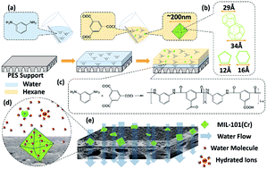
MOFs, which are hybrid organic–inorganic solid compounds constructed from metal containing nodes and organic linkers, have attracted considerable attention of researchers since stable pore structure of them can be obtained.26–30 Due to their structural and functional properties, such as ultrahigh and controlled porosity, large internal surface areas, tunable pore size and type, affinity for specific ions and molecules, MOFs have been studied extensively for gas adsorption and separation31–37 with advancements in fabricating molecular sieve membranes and mixed matrix membranes.38–41 However, studies of the relative fields, liquid purification and separation using MOFs, lag behind. Recent studies just have begun to focus on the application of MOFs in liquid treatment. Organic solvent NF and pervaporation have been carried out for recovery and filtration of organic liquid with membranes based on MOFs.42–47 Basu et al. incorporated MOFs [HKUST-1, MIL-47, ZIF-8 and MIL-53(Al)] in polydimethylsiloxane membranes to separate Rose Bengal (RB) from isopropanol, the modified membranes showed higher retention of RB than unfilled membranes.42 Liu et al. fabricated organophilic pervaporation membranes by incorporating ZIF-8 nanoparticles in silicone rubber membranes, the ZIF-8 doped membranes showed promising performance for recovering bio-alcohols from dilute aqueous solution.43 Sorribas et al. reported MOFs [ZIF-8, MIL-53(Al), NH2-MIL-53(Al) and MIL-101(Cr)] doped TFN membranes for the separation of styrene oligomers from methanol and tetrahydrofuran, the permeate fluxes of PA/MOFs membranes were 1.6–5.5 times higher than the PA membrane.23 Whereas these research results cannot copy to water treatment field in case of the hydration reaction involving ligand displacement and/or hydrolysis would destroy the topology structure and affect the properties of some MOFs (e.g., MOF-5 and HKUST-1).48–51 Therefore, hydrostable MOFs deserve more attention with the potential application in water treatment.
In this work, Cr-BDC MOFs [MIL-101(Cr)], a chromium based mesoporous MOFs with two types of cages of 2.9 nm/3.4 nm diameter and 1.2 nm pentagonal/1.6 nm hexagonal openings52 (Fig. 1), was firstly applied in manufacturing TFN membranes for water treatment. Compared with other water stable MOFs (e.g., ZIF-8 and UIO-66),24,48,53 MIL-101(Cr) possesses larger pore volumes and surface area, which means more and broader water channels can be provided. As a hydrophilic material, MIL-101(Cr) is expected to upgrade the surface hydrophilicity of membranes by attracting more water molecules than hydrophobic MOFs. Furthermore, most windows of the cages of MIL-101(Cr) are pentagonal, and the channel architecture without breathing effects is expected to be unyielding during water treatment process under operation pressure.54 By membrane performance test we found that thin film MIL-101(Cr) nanocomposite (TFMN) membranes prepared by interfacial polymerization on polyether sulfone (PES) ultrafiltration (UF) support appeared high and time stable water permeability. With differing MIL-101(Cr) loading, the surface topography and internal structure of PA layer were changed, which brought the differences of water permeance and rejection of membranes. These differences can be designed and used for manufacturing tailor-made membranes applied in diverse water treatment conditions.
The synthesis of MIL-101(Cr) was carried out as previously reported,55 its structure was confirmed by X-ray diffraction (XRD) (Fig. S1†), and the diffraction peaks agree with the reported result, indicating the as-synthesized material was MIL-101(Cr). Noteworthy that the particle size of MIL-101(Cr) was controlled to be around 200 nm, characterized by Scanning Electron Microscopy (SEM) (Fig. S1†), to best match the thickness of PA dense selective layer (100–300 nm) by adjusting the synthesis time. Similarity between the MIL-101(Cr) nanoparticles size and the PA layer thickness can guarantee establishing longer water channels. Compared to the smaller or larger nanoparticles, better support provided by size matched MIL-101(Cr) nanoparticles for PA layer was expected and indeed observed in the membrane performance test, which can resist the pressure induced compaction and rearrangement of the polymer chains. Encouraged by the high Brunauer–Emmet–Teller (BET) surface area (3264 m2 g−1) calculated by measuring nitrogen gas (N2) adsorption and high water absorption capacity [1.67 g water per g MIL-101(Cr)] calculated by water adsorption experiment, we employed MIL-101(Cr) nanoparticles into fabricating membranes for water treatment. Our strategy for in situ preparing TFMN membranes was directly adding MIL-101(Cr) into a 0.1 w/v% trimesoyl chloride (TMC) hexane solution and then pouring the mixed solution onto a PES UF support which had been immersed in a 2 w/v% m-phenylenediamine (MPD) aqueous solution for 2 min (Fig. 1). After 1 min interfacial polymerization progress, PA layer doped with MIL-101(Cr) nanoparticles formed on the PES UF support (Fig. 1).23 TFC membranes without MIL-101(Cr) nanoparticles and TFMN membranes obtained by adding MIL-101(Cr) nanoparticles into MPD aqueous solution were also prepared as controls.
Compared with TFMN (A) membranes prepared by adding MIL-101(Cr) nanoparticles into aqueous solution (MPD aqueous solution), TFMN (O) membranes prepared by adding MIL-101(Cr) nanoparticles into organic solution (TMC hexane solution) showed better integrity, which can be observed in cross section SEM images (Fig. 2). There is a clear boundary between the PA layer and the PES support of the TFMN (A) membrane, which means an untight adhesion. Unlikely, no boundaries appear in the TFC or TFMN (O) membrane. In the interfacial polymerization process, the forming of PA layer mainly relies on the diffusing of monomers in aqueous phase (MPD).10,16,25,56,57 While adding MIL-101(Cr) nanoparticles into the aqueous solution, the movement of the monomers in aqueous phase was affected, the finally formed PA layer of the TFMN (A) membrane was above the nanoparticles, which resulted in a weak combination of the PA layer, MIL-101(Cr) nanoparticles and PES UF support. Whereas the diffusions of MPD were less interfered in TFMN (O) membranes forming process as MIL-101(Cr) nanoparticles only existed in the organic solution. Finally formed PA layer can wrap MIL-101(Cr) nanoparticles closely without visible voids. Our study by Attenuated Total Reflection Flourier Transformed Infrared (ATR-FTIR) spectra (Fig. 2) also indicates that the combination of MIL-101(Cr) nanoparticles and PA layer is close in TFMN (O) membranes. Bands between 1700–1300 cm−1 correspond to ν(C–C), νs(COO), and νas(COO) vibrations, implying the presence of dicarboxylate linker in MIL-101(Cr).23 The most intense peak (1405 cm−1) can be used to confirm the presence of MIL-101(Cr) nanoparticles in PA layer. This peak appears in the spectrum of the TFMN (O) membrane, whereas it is not present in the spectrum of the TFMN (A) membrane. MIL-101(Cr) nanoparticles cannot be detected by depth limited ATR-FTIR in the TFMN (A) membrane, confirming again that MIL-101(Cr) nanoparticles are under PA layer, which infers that there is no through channels existed in the dense selective layer. In contrast, the bands in the spectrum of the TFMN (O) membrane remained about the same even after 50 h membrane performance test, indicating that a PA-MIL-101(Cr) structure was formed and could maintain in a long time during pressure-driven water treatment process.
Differing the amount and the method of MIL-101(Cr) nanoparticles addition, surface morphologies of TFMN membranes changed. The SEM image of the pristine TFC membrane (Fig. 3) shows a typical “ridge and valley” structure of the dense PA layer.58 With the increase of the loading of MIL-101(Cr) nanoparticles from 0.025 w/v% to 0.4 w/v%, surface morphologies of both TFMN (O) (Fig. 3) and TFMN (A) (Fig. S2†) membranes changed from the “ridge and valley” structures to smoother structures. Especially when increasing over 0.2 w/v% MIL-101(Cr) concentration, the “ridge and valley” structures almost disappear. Compared with TFMN (O) membranes, these surface morphologies changes are more obvious in TFMN (A) membranes. It is apparent that both the MIL-101(Cr) concentration and added phase can affect the membrane morphologies. The different morphologies of the membranes are the manifestation of the different crosslinking extent. It is widely accepted that high crosslinking extent of the dense PA layer is requisite to obtain membranes with high rejection and stability. High concentration of MIL-101(Cr) nanoparticles would bring adverse effects to the crosslinking extent of PA layer during the forming process, so that there is a limit of the addition of MIL-101(Cr). As discussed above, the migration of MPD from the aqueous phase to the organic phase, which is the key step to form PA structure, was affected by MIL-101(Cr) nanoparticles dispersed in the aqueous phase; while this migration was less affected when MIL-101(Cr) nanoparticles were dispersed in the organic phase. Moreover, when adding hydrophilic MIL-101(Cr) nanoparticles into the aqueous phase, the interaction between the organic phase and the MIL-101(Cr) nanoparticles impeded the miscibility of MPD and TMC; whereas the hydrophilic MIL-101(Cr) nanoparticles existed in the organic phase may help the MPD diffusing by their attraction to the aqueous phase.25 It is indicated that the organic phase is the suitable phase for MIL-101(Cr) nanoparticles addition. Hereafter, TFMN membranes characterization and performance test will focus on TFMN (O) membranes.
The Atomic Force Microscope (AFM) three dimensional images of the TFC and TFMN (O) membranes are shown in Fig. S3† and the results of roughness analysis (Rq) are listed in Table 1. With the increase of the MIL-101(Cr) loading, the membranes surface became rougher and their Rq values increased. The roughness properties differences among these membranes, mainly due to the aggregation of MIL-101(Cr), are consistent with the SEM images of the membranes surface. As can be seen in Fig. 3, MIL-101(Cr) nanoparticles or aggregates were not all encapsulated but some semi-exposed in the PA layer (Fig. S4†). At low concentration (<0.1 w/v%), MIL-101(Cr) nanoparticles were well dispersed in the organic phase, most of them incorporated in situ during the interfacial polymerization and finally resided in the middle of the selective layer, so that there were only a small amount of MIL-101(Cr) nanoparticles can be seen from the SEM images of the membrane surface. When increasing over 0.1 w/v% MIL-101(Cr) concentration, the aggregation of the nanoparticles, which was existed in the dispersed phase and then introduced into interfacial polymerization, was difficult to avoid. The fillers with a large size affected the film growth and finally resided on the top of the selective layer. With the increase of the MIL-101(Cr) loading, more semi-exposed fillers can be seen in the membrane surface (Fig. 3). The semi-exposed fillers brought bumps to the membranes surface, causing a significant increase in roughness. The hydrophilic properties of the TFC and TFMN (O) membranes were tested by water contact angle measurements as listed in Table 1. Decreased water contact angle value (θ) were obtained with increasing MIL-101(Cr) loadings. Contact angle can be different due to the hydrophilic or hydrophobic functional groups in the filler and polymer. In this work, all the prepared TFC and TFMN (O) membranes have hydrophilic surfaces (θ < 90°) due to the hydrophilic carboxylic acid groups of PA and the hydrophilic hydroxyl groups of MIL-101(Cr).23,59,60 As mentioned earlier, the crosslinking extent of PA layers decrease with increasing MIL-101(Cr) concentration. The crosslinking extent can be reflected by the element ratios of O/N and C/N.24 The element composition of the surface (Table 1) was measured by X-ray photoelectron spectroscopy (XPS). Both O/N and C/N increase with increasing MIL-101(Cr) loadings, indicating less crosslinking extent. The less crosslinking extent means more unreacted acyl chloride groups in TMC and then more generated carboxylic acid groups in PA layer, which attribute to the θ decreasing. The surface roughness also plays an important role on surface hydrophilic properties, increased roughness can amplify the θ value decreasing. Therefore, the addition of MIL-101(Cr) fillers in PA structure enhanced membrane hydrophilic, which is beneficial to improving the membranes performance in water treatment process by attracting more water molecules. Moreover, hydrophilized membrane surface can enhance the stability of membrane by reducing membrane fouling.61
MIL-101(Cr) (w/v%) | Cra (%) | Ca (%) | Oa (%) | Na (%) | O/N (−) | C/N (−) | Rqb (nm) | θc (°) |
---|---|---|---|---|---|---|---|---|
a Cr, C, O, N element atomic concentration obtained directly from XPS.b Root-mean-square surface roughness obtained from AFM, error bars based on at least three measurements.c Apparent water contact angle, error bars based on at least three measurements. | ||||||||
0 | 0 | 76.67 | 13.96 | 9.37 | 1.49 | 8.18 | 46 ± 4 | 64 ± 2 |
0.025 | 0.04 | 76.49 | 14.23 | 9.24 | 1.54 | 8.28 | 52 ± 2 | 53 ± 2 |
0.05 | 0.06 | 75.75 | 14.92 | 9.27 | 1.61 | 8.17 | 53 ± 1 | 52 ± 2 |
0.1 | 0.07 | 76.24 | 14.85 | 8.84 | 1.68 | 8.62 | 55 ± 3 | 48 ± 3 |
0.2 | 0.15 | 76.31 | 15.01 | 8.53 | 1.76 | 8.95 | 59 ± 4 | 46 ± 2 |
0.4 | 0.34 | 75.73 | 15.68 | 8.25 | 1.90 | 9.18 | 73 ± 2 | 42 ± 4 |
With the high porosity and the nanoscale pore size, MIL-101(Cr) is expected to improve membrane performance by increasing membrane water permeance but not decreasing selectivity. However, it is observed in membrane desalination performance test that TFMN (O) membranes exhibited higher fluxes but lower rejections than the TFC membrane. Fig. 4 shows the effects of MIL-101(Cr) loadings for rejecting NaCl salts from water. Adding very small amount of MIL-101(Cr) (0.025 w/v%) increased water permeance by 59% and only decreased NaCl rejection by 2.3%. At 0.05 w/v%, the water permeance of the TFMN (O) membrane was 76% higher than the TFC membrane and keep the NaCl rejection higher than 90%. With increasing the MIL-101(Cr) loadings up to 0.4 w/v%, the water permeance of the TFMN (O) membrane was 180% higher than the TFC membrane. However, this high water permeance is relative with low NaCl rejection. Fig. 4 shows the effects of MIL-101(Cr) loadings for rejecting Na2SO4 salts from water. With the same increasing trend of water permeance, TFMN (O) membranes exhibited a better performance for rejecting Na2SO4 salts from water compared with rejecting NaCl salts. The rejection maintained a high level (over 90%) with increasing the MIL-101(Cr) loadings up to 0.2 w/v%. The large gap between the rejections of NaCl and Na2SO4 salts indicates that TFMN (O) membranes has the ability to separate different valent ions. It is apparent that the desalination properties of TFMN (O) membranes changed significantly compared to the TFC membrane. The flux enhancements of TFMN (O) membranes is caused by a combination of the porous structure of MIL-101(Cr), the hydrophilicity of MIL-101(Cr) and the lower crosslinking extent of PA structure. Water molecules can be attracted to the direct channels established by MIL-101(Cr) in the dense selective layer and transport through fast, while hydrated ions can be excluded by the MIL-101(Cr) pores. The rejections decrease is mainly caused by the aggregates of MIL-101(Cr) nanoparticles. Although the better compatibility between MIL-101(Cr) nanoparticles and the PA layer than traditional inorganic fillers is benefit to avoid nonselective voids formed in the dense PA layer, inner voids of MIL-101(Cr) aggregates and interfacial defects between PA and the aggregates is inevitable with increasing MIL-101(Cr) loadings. These voids are nonselective to salts, consequently the rejections decrease. By membrane stability test, we found out that the changes in membranes desalination properties caused by MIL-101(Cr) implantation were stable. As shown in Fig. 4, there is a 29% flux decline of the TFC membrane after 50 h test, while with the addition of MIL-101(Cr), the flux downward trend is lessened. At 0.025 w/v% and 0.05 w/v%, the rate of flux decline of the after test membranes are 9.6% and 7.4%, respectively. With increasing the MIL-101(Cr) concentration over 0.1 w/v%, the flux of membranes is no longer declining. MIL-101(Cr) nanoparticles are hydrostable, and their rigid pore structure would not be damaged under the operation pressure in the test process.54 So the MIL-101(Cr) nanoparticles in the PA layer can play a supporting role to resist the pressure induced compaction and the rearrangement of polymer chains, which leads to the stability of the membranes flux. It can be seen in Fig. S5† that the Na2SO4 rejection of the membranes also can remain stable during the 50 h stability test except the TFMN (O) 0.4 w/v%. High concentration of MIL-101(Cr) nanoparticles introduced aggregates may be dropped off during the long time test, which brought non-selective defects to the membranes. In this study, the MIL-101(Cr) concentration in a range of 0.025–0.2 w/v% to prepare the TFMN (O) membranes can bring stable water performance changes to the membranes, and the membranes selectivity cannot be improved by further increasing the MIL-101(Cr) concentration. The lower and unstable rejections at higher MIL-101(Cr) concentration may be expected to be improved by improving MIL-101(Cr) dispersion to avoid aggregates and defects.
The steady changes of membrane properties caused by MIL-101(Cr) nanoparticles addition can be used to design tailor-made membranes according to difference needs. As the water permeance of membranes can increase with increasing the MIL-101(Cr) nanoparticles addition, the design was mainly focused on the membrane rejection. When adding a small amount of MIL-101(Cr) nanoparticles (<0.05 w/v%), the NaCl rejection of the TFMN (O) membranes can keep higher than 90%. These TFMN (O) membranes can be used in RO process, like seawater desalination. With the MIL-101(Cr) nanoparticles addition increasing, the higher fluxes were with lower NaCl rejections, these membranes can be used as NF membranes for separation of monovalent and divalent ions or dye removal. In this work, membrane rejection was further characterized by using high molecular weight polyethylene glycol (PEG). Solutions of PEG oligomer mixtures with an average molecular weight (MW) of 200, 400, 600, 800 and 1000 Da were used for test. It can be seen in Fig. S6† that the TFMN (O) 0.025 w/v% and TFMN (O) 0.05 w/v% membranes has an over 90% rejection of PEG-200, the TFMN (O) 0.1 w/v% membrane has an over 90% rejection of PEG-400, the TFMN (O) 0.2 w/v% membrane has an over 90% rejection of PEG-600 and the TFMN (O) 0.4 w/v% membrane has an over 90% rejection of PEG-1000. The test results can provide guidance for the application of the TFMN (O) membranes. As an application of validation, 100 ppm methyl orange (MW: 327.33) solution, methyl violet (MW: 408.03) solution, congo red (MW: 696.68) solution and methyl blue (MW: 799.80) solution were processed by different TFMN (O) membranes according to the dye molecular weight. To achieve higher water flux, the removal of dye molecules with higher MW were used by TFMN (O) membranes with higher MIL-101(Cr) concentration based on the results of PEG rejection test. As can be seen in Fig. 4, both high dye rejections (>95%) and higher water fluxes can be guaranteed. The large size and self-assembly property of dye molecules are beneficial to the dye removal process.25 The before and after photos of dye removal test can be seen in Fig. S7.† Note that the fluxes of the same TFMN (O) membrane for dye removal are 74% (methyl orange/TFMN (O) 0.025 w/v%), 79.9% (methyl violet/TFMN (O) 0.05 w/v%), 89.2% (congo red/TFMN (O) 0.1 w/v%) and 87.2% (methyl blue/TFMN (O) 0.1 w/v%) of the fluxes for desalination (Na2SO4), the high dye concentration may enhance the concentration polarization effect and the membrane fouling may occur during the test. Therefore, the significant sieve effect of the TFMN (O) membranes on different dye molecules indicating that the TFMN (O) membranes have a great potential in water treatments for the removal of targeted large organic molecules.
Footnote |
† Electronic supplementary information (ESI) available: Experimental details. See DOI: 10.1039/c6ra16896e |
This journal is © The Royal Society of Chemistry 2016 |