Recovery of cobalt from spent lithium ion batteries using sulphuric acid leaching followed by solid–liquid separation and solvent extraction
Feng Wanga,
Rong Sun*a,
Jun Xub,
Zheng Chenb and
Ming Kanga
aState Key Laboratory Cultivation Base for Nonmetal Composites and Functional Materials, School of Materials Science and Engineering, Southwest University of Science and Technology, Mianyang 621010, China. E-mail: sunrong@swust.edu.cn; Tel: +86-816-13547133946
bSichuan Changhong Electric Co., Ltd., Mianyang 621010, China
First published on 10th August 2016
Abstract
Herein, the method of hydrometallurgy is adopted to recycle the precious metal cobalt in spent lithium ion batteries (LIBs). The best experimental conditions for leaching cobalt ions in sulphuric acid–hydrogen peroxide system are studied. The best leaching operation condition is an H2SO4 concentration of 3.0 mol L−1, liquid–solid ratio of 7![[thin space (1/6-em)]](https://www.rsc.org/images/entities/char_2009.gif) :
:![[thin space (1/6-em)]](https://www.rsc.org/images/entities/char_2009.gif) 1 and hydrogen peroxide dosage of 1.6 mL g−1 for 2.5 h at 70 °C. Using the extraction characteristics of D2EHPA (di-(2-ethylhexyl) phosphoric acid) and PC-88A (2-ethylhexyl phosphonic acid mono-2-ethylhexyl ester) for a specific ion in different pH value leaching solutions, the best experimental conditions are D2EHPA and PC-88A saponification rates of 20% and 30%, respectively, sulfonated kerosene volume of 70%, oil–water (O/A) ratio of 1
1 and hydrogen peroxide dosage of 1.6 mL g−1 for 2.5 h at 70 °C. Using the extraction characteristics of D2EHPA (di-(2-ethylhexyl) phosphoric acid) and PC-88A (2-ethylhexyl phosphonic acid mono-2-ethylhexyl ester) for a specific ion in different pH value leaching solutions, the best experimental conditions are D2EHPA and PC-88A saponification rates of 20% and 30%, respectively, sulfonated kerosene volume of 70%, oil–water (O/A) ratio of 1![[thin space (1/6-em)]](https://www.rsc.org/images/entities/char_2009.gif) :
:![[thin space (1/6-em)]](https://www.rsc.org/images/entities/char_2009.gif) 1, and extraction time of 10 min. Two extractions are applied, the first extraction occurs at pH 2.70 and the second extraction is done at pH 2.60 using D2EHPA to remove copper and manganese ions. After the extraction operation, PC-88A is used to further extract the leaching solution and maintain the pH at 4.25, so that cobalt and nickel ions are effectively separated, then cobalt ions are separated by oxalic acid and cobalt oxalate is obtained. The purity of cobalt is as high as 99.50%.
1, and extraction time of 10 min. Two extractions are applied, the first extraction occurs at pH 2.70 and the second extraction is done at pH 2.60 using D2EHPA to remove copper and manganese ions. After the extraction operation, PC-88A is used to further extract the leaching solution and maintain the pH at 4.25, so that cobalt and nickel ions are effectively separated, then cobalt ions are separated by oxalic acid and cobalt oxalate is obtained. The purity of cobalt is as high as 99.50%.
1. Introduction
The demand for sustainable and clean energy is becoming more and more critical owing to the emergence of applications for the many new types of electronic devices currently available.1 The world's major countries vigorously promote the electric car, which increases the intensity of power battery research, especially lithium-ion batteries (LIBs).2 Compared with lead-acid batteries, nickel cadmium batteries and nickel metal hydride batteries, the lithium ion battery presents the advantage of a superior performance, such as high working voltage, large energy density, no memory effect, low self-discharge rate and long cycle life, thus it is widely used in consumer electronics. Owing to the constant introduction of new technologies, which result in the shorter use of electronic products cycle lifespans, spent LIBs have increased rapidly in recent years.3–5At present, the treatment methods for spent LIBs mainly include incineration, landfills, and recycling. If unsuitable disposal of these batteries are carried out, serious environmental problems are generated due to their hazardous constituents, which include heavy metals and electrolytes. Cobalt, which is contained in spent LIBs, is a highly toxic metal and could cause cancer owing to its strong permeability. The price of cobalt has increased significantly in recent years,6 however the content of cobalt in LIBs is up to 5–20%, which is far beyond the average ore. Therefore, effective recycling does not only reduce production costs but also protects the environment.7,8
In order to efficiently recover the cobalt metal from cathode materials, various physical and chemical methods have been reported,9–14 and the most common recovery processes include prometallurgy,15 hydrometallurgy,16 and biometallurgy.17
The hydrometallurgy process is employed for the recovery of cobalt ions because of its high rate of recovery, low energy consumption and limited generation of waste water and gas. The hydrometallurgy process includes crushing, dismantling, sieving, leaching, solvent extraction, chemical precipitation and eletrochemistry.18 Hydrometallurgy is considered a good recycling process for the recovery of spent LIBs. Cobalt, lithium and other metal ions are easily leached from spent LIBs using inorganic acids as leached agents, such as HCl, HNO3, and H2SO4,19–21 and extra reducing agents, such as hydrogen peroxide (H2O2), are added so as to accelerate the leaching process of metal ions.
To date, a large number of methods to recover metals from the leaching liquor of spent LIBs have been proposed.22,23 According to the relevant research, the main techniques are listed in Table 1.24–27 However, the important drawback of these techniques is the low purity of the cobalt compounds. Therefore, it is urgent to exploit new recovery processes to meet the demand of metal recycling from the already complicated waste streams.28,29
| Extraction agents | Extraction conditions | Extraction of metal ions | References |
|---|---|---|---|
| Cyanex 272 | Stoichiometric ratio Cyanex 272/Co = 4, pH 5–6 | Co | 23 |
| D2EHPA | Stoichiometric ratio D2EHPA/Mn = 2, pH 4 | Mn | |
| Cyanex 272 | Cyanex 272 (monomeric basis) dissolved in diluent Exxsol D-80. Cyanex 272 sequence extraction: Al3+ > Co2+ > Li+. The pH1/2 values obtained are 3.0 for aluminium, 4.0 for cobalt and 6.5 for lithium | Al, Co, Li | 24 |
| PC-88A | The extractant PC-88A was saponified by NaOH solution, sulfonated kerosene was used as the diluent and tri-n-butylphosphate was used as the phase modifier | Co | 25 |
| Mextral 5640H | Equilibrium pH of 2.06. 10 vol% Mextral 5640H and A/O = 2![[thin space (1/6-em)]](https://www.rsc.org/images/entities/char_2009.gif) : :![[thin space (1/6-em)]](https://www.rsc.org/images/entities/char_2009.gif) 1 1 |
Cu | 26 |
| Mextral 272P | Time-5 min, equilibrium pH of 5.50, A![[thin space (1/6-em)]](https://www.rsc.org/images/entities/char_2009.gif) : :![[thin space (1/6-em)]](https://www.rsc.org/images/entities/char_2009.gif) O = 2/1 and 30 vol% Mextral 272P O = 2/1 and 30 vol% Mextral 272P |
Co |
Solvent extraction has been widely used for the recovery and separation of metals from leach liquor.30 In order to obtain high purity metal concentrates, solvent extraction has been paid more attention, which appears to satisfy the requirements of performance and economics.
In the current study, recycling of components in spent LIBs is done via the hydrometallurgical process. The experiment focuses on the extraction and purification of cobalt in the leaching liquor of spent LIBs. H2SO4 is employed as the leaching agent, with H2O2 as the reducing agent. The effect of leaching conditions, such as temperature, time, concentration of H2SO4, liquid–solid ratio and H2O2 dosage on efficiency is determined. Also, an orthogonal experiment was designed to examine the relationship between the factors and the optimal experimental conditions. A solvent extraction process has been developed to preliminarily and selectively remove manganese and copper from the leach liquor using D2EHPA. Subsequently, cobalt can be selectively separated from the liquid phase containing cobalt and nickel using PC-88A.
2. Experimental
2.1. Materials and reagents
Spent LIBs were supplied by ChangHong Electric Co., Ltd. (Mianyang, China) and the cathode material was obtained from spent LIBs after pretreatment (detailed description in the next section). Sulfuric acid (H2SO4) was tested as the leaching agent. Hydrogen peroxide (H2O2 30%) was used as an additional reductant. For the extraction tests, di-(2-ethylhexyl) phosphoric acid (D2EHPA, 95.7% in purity) and 2-ethylhexyl phosphonic acid mono-2-ethylhexyl ester (PC-88A, 95% in purity) were used as extractant agents, and these were saponified by a sodium hydroxide solution (10 mol L−1). Low boiling point sulfonated kerosene (180–270 °C) was used as the diluent and tri-n-butylphosphate (TBP, 96.8% in purity) was used as the phase modifier. In the precipitation step, oxalate (analytical grade) was used as the precipitating agent.All other solutions were prepared with ultrapure water and all chemical reagents were used without further purification and supplied by Chengdu Kelong Chemical Reagent Co., Ltd., China.
2.2. Preparation of LIBs cathode material
The batteries used to obtain the cathode material were procured from ChangHong Electric Co., Ltd. (Mianyang, China). Firstly, LIBs were crushed using wet crushing, secondly, large particles were removed using a vibrating screen and then the residue was dried at 105 °C for 2 h. Images of the residue are shown in Fig. 1a.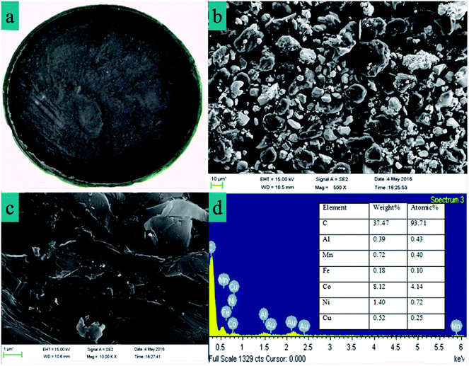 | ||
| Fig. 1 (a) Images of the cathode material from a spent LIB. (b) and (c) SEM images of the cathodic material powder. (d) EDX with the elemental analysis of the cathode material powder. | ||
2.3. Analytical methods
The spent LIBs cathode material and precipitated of cobalt oxalate was characterized using an X-ray diffractometer (XRD PANalytical Axios, Cu-Ka). X-ray fluorescence (XRF PANalytical Axios, Rh-Ka) was also used to characterize the spent LIBs cathode material. Scanning electron microscopy (SEM) microphotographs and elemental composition analysis were obtained using a Carl Zeiss Ultra 55 field emission SEM (FE-SEM) equipped with an energy-dispersive X-ray (EDX) detector operating at 15 kV. The pH values of the aqueous solutions were measured with a pH/mV meter (Model PHS-3C+) and Fourier transform infrared spectroscopy (FT-IR, Nicolet-5700, PerkinElmer Instruments Corporation) was employed for the identification of the relevant vibrational characteristic bands of cobalt oxalate. The metal ions were identified via an inductively coupled plasma optical emission spectrometry (ICP, AES-ICAP6500) which is very accurate with high sensitivity to estimate rare elements. In this research, thermal analyses of the spent LIBs powder were performed using a Thermo-gravimetric Analyzer (TG, Q500 TGA USA) in a nitrogen atmosphere from 30 to 1000 °C at a heating rate of 10 °C min−1.2.4. Metal leaching
H2SO4 and H2O2 (30%) were used to leach Co2+ from the spent LiBs. This experiment was carried out at a set temperature with a reflux condenser, and the Co2+ leaching process was optimized by orthogonal experimental conditions, L16(45). Generally, the leaching process is mainly influenced by the concentration of H2SO4, temperature, leaching reaction time, dosage of H2SO4 solid-to-liquid ratio (S![[thin space (1/6-em)]](https://www.rsc.org/images/entities/char_2009.gif) :
:![[thin space (1/6-em)]](https://www.rsc.org/images/entities/char_2009.gif) L), and H2O2 dosage. Firstly, a diluted H2SO4 solution was added to three flasks, then the spent LIBs cathode material (30.0000 g) was added to the diluted H2SO4 solution, and lastly, H2O2 was dropped into the solution which was mixed using a magnetic stirrer. After the reaction, the residue was filtered, washed and the leaching filtrate was collected in the constant volume of 1000 mL. The concentration of cobalt and other metal ions was detected. The factors and levels of the orthogonal experiment are listed in Table 2.
L), and H2O2 dosage. Firstly, a diluted H2SO4 solution was added to three flasks, then the spent LIBs cathode material (30.0000 g) was added to the diluted H2SO4 solution, and lastly, H2O2 was dropped into the solution which was mixed using a magnetic stirrer. After the reaction, the residue was filtered, washed and the leaching filtrate was collected in the constant volume of 1000 mL. The concentration of cobalt and other metal ions was detected. The factors and levels of the orthogonal experiment are listed in Table 2.
| Levels | Factors | ||||
|---|---|---|---|---|---|
| T (°C) | t (h) | [Acid] (M) | [H2O2] (vol%) | S![[thin space (1/6-em)]](https://www.rsc.org/images/entities/char_2009.gif) : :![[thin space (1/6-em)]](https://www.rsc.org/images/entities/char_2009.gif) L (g mL−1) L (g mL−1) |
|
| 1 | 50 | 1.5 | 2.0 | 1![[thin space (1/6-em)]](https://www.rsc.org/images/entities/char_2009.gif) :1.1 :1.1 |
1![[thin space (1/6-em)]](https://www.rsc.org/images/entities/char_2009.gif) : :![[thin space (1/6-em)]](https://www.rsc.org/images/entities/char_2009.gif) 5 5 |
| 2 | 60 | 2.0 | 2.5 | 1![[thin space (1/6-em)]](https://www.rsc.org/images/entities/char_2009.gif) : :![[thin space (1/6-em)]](https://www.rsc.org/images/entities/char_2009.gif) 1.2 1.2 |
1![[thin space (1/6-em)]](https://www.rsc.org/images/entities/char_2009.gif) : :![[thin space (1/6-em)]](https://www.rsc.org/images/entities/char_2009.gif) 6 6 |
| 3 | 70 | 2.5 | 3.0 | 1![[thin space (1/6-em)]](https://www.rsc.org/images/entities/char_2009.gif) : :![[thin space (1/6-em)]](https://www.rsc.org/images/entities/char_2009.gif) 1.3 1.3 |
1![[thin space (1/6-em)]](https://www.rsc.org/images/entities/char_2009.gif) : :![[thin space (1/6-em)]](https://www.rsc.org/images/entities/char_2009.gif) 7 7 |
| 4 | 80 | 3.0 | 3.5 | 1![[thin space (1/6-em)]](https://www.rsc.org/images/entities/char_2009.gif) : :![[thin space (1/6-em)]](https://www.rsc.org/images/entities/char_2009.gif) 1.4 1.4 |
1![[thin space (1/6-em)]](https://www.rsc.org/images/entities/char_2009.gif) : :![[thin space (1/6-em)]](https://www.rsc.org/images/entities/char_2009.gif) 8 8 |
2.5. Effect of initial pH on concentration of metal ions in the leaching solution
The appropriate pH value of 800 mL of leaching solution was adjusted by the addition of 2.0 mol L−1 sodium hydroxide solution and maintained for 10 min. The initial pH adjustment produced a small amount of floc. The purified solution and some micro precipitates were separated by filtration. The content of each metal in the filtrate was measured.2.6. Solvent extraction
Hydrometallurgy is the main method used to recycle cobalt metal from spent LIBs, and the leaching of cobalt ions from cathodic material is carried out by H2SO4–H2O2 systems. However, leaching liquors not only contain cobalt ions but also nickel, copper and manganese metal ions. It is extremely difficult to obtain pure cobalt compounds from these complicated leaching liquors, because nickel, manganese, and copper possess similar physico-chemical properties. A clever method to obtain high purity cobalt is of the use of an extraction agent which could separate cobalt and other metal ions efficiently. To our knowledge, there are no reports on a selective extraction agent which could extract cobalt ion efficiently and separate other metal ions. Therefore, the key is to obtain high purity cobalt using a combination of several extraction agents.The cobalt–nickel separation factors from H2SO4 media using phosphoric, phosphonic and phosphinic acids have been reported in the literature. The separation ability of cobalt and nickel increases in the order phosphinic > phosphonic > phosphoric acid due to the increasing stabilisation of tetrahedral coordination cobalt compounds with the extractant in the organic phase, because tetrahedral compounds are more lipophilic than octahedral compounds.31–33 The organophosphorus extractants D2EHPA and PC-88A in H2SO4 medium possess excellent extraction characteristics for the metals manganese, copper and nickel.34,35 However, maintaining a constant pH value is essential before and after the extraction process, because the extraction abilities of D2EHPA and PC-88A are closely related to the pH of the liquid. In order to keep the pH stable, D2EHPA and PC-88A were saponified by 10 mol L−1 sodium hydroxide solution. The saponification ratio of D2EHPA and PC-88A in the test was 20% and 30% (mole percent), respectively. Sulfonated kerosene was used as the diluent (dilution was implemented by mixing 30 vol% D2EHPA or PC-88A with 70 vol% sulfonated kerosene) and 5 vol% tri-n-butylphosphate was used to modify the phase separating agent. Batch contacts with the phase ratio of O/A = 1![[thin space (1/6-em)]](https://www.rsc.org/images/entities/char_2009.gif) :
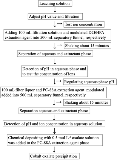
:![[thin space (1/6-em)]](https://www.rsc.org/images/entities/char_2009.gif) 1 were used (100 mL volume of leaching liquid and 100 mL modulated extractant solution). Extraction and separation were strictly conducted at room temperature in a 500 mL separatory funnel by manual shaking for about 15 min and then resting for 10 min. Subsequently, the aqueous phase was taken for analysis after phase separation. The pH of the aqueous solution was adjusted to the desired value by adding dilute H2SO4 or NaOH before equilibration. Finally, the acidity of the aqueous phase was tested using a digital pH meter. The concentration of metal in the filter liquor was determined by ICP-AES. The recovery rate of the extraction fraction can be measured by the ratio of the cobalt ion concentration in the final extraction reagent PC-88A to the cobalt ion concentration in the initial leaching solution. The main steps in extraction process are shown in Fig. 2.
1 were used (100 mL volume of leaching liquid and 100 mL modulated extractant solution). Extraction and separation were strictly conducted at room temperature in a 500 mL separatory funnel by manual shaking for about 15 min and then resting for 10 min. Subsequently, the aqueous phase was taken for analysis after phase separation. The pH of the aqueous solution was adjusted to the desired value by adding dilute H2SO4 or NaOH before equilibration. Finally, the acidity of the aqueous phase was tested using a digital pH meter. The concentration of metal in the filter liquor was determined by ICP-AES. The recovery rate of the extraction fraction can be measured by the ratio of the cobalt ion concentration in the final extraction reagent PC-88A to the cobalt ion concentration in the initial leaching solution. The main steps in extraction process are shown in Fig. 2.
2.7. Chemical precipitation of cobalt oxalate
In order to precipitate the precious metal cobalt, which was obtained via the extraction process, the chemical precipitation method was applied. Cobalt was precipitated from the strip liquor of PC-88A extractant by the addition of excess 0.5 mol L−1 oxalate. In addition, the solubility integrals of copper, manganese, nickel and cobalt are 4.4 × 10⁻¹⁰, 1.7 × 10⁻⁷, 4.0 × 10⁻¹⁰ and 6.3 × 10⁻⁶, respectively, in oxalic acid solution.36 The solubility of the cobalt ion product is higher and it is easier to precipitate compared with other metal ions. Furthermore, the concentration of cobalt ion is far higher than that of the other metal ions in the extractant PC-88A phase, thus cobalt is precipitated by oxalate more easily and can realize efficient separation among other ions. The precipitating process could be expressed by the chemical reaction equation: Co(aq)2+ + C2O4(aq)2− + 2H2O ⇒ CoC2O4·2H2O(s). After filtration and washing, the precipitated cobalt oxalate was obtained and then characterized via IR, XRD and ICP.3. Results and discussion
3.1. Characterization of the spent LIBs cathode material composition
The spent LIBs cathode material XRD pattern is shown in Fig. 3b. The strong diffraction intensity of the peak at the 2θ of 26.50° clearly indicates that the main composition of the cathode material was graphite with an integrated graphite layered structure. It can be noted that graphite materials basically retain good crystallinity and have a completely layered structure.37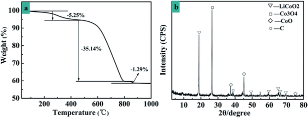 | ||
| Fig. 3 (a) Thermogravimetric properties of the cathode materials of a spent LIB. (b) XRD pattern of the cathodic materials from a spent LIB. | ||
The peak at 18.50° is due to LiCoO2. From this data, the crystalline LiCoO2 phase is clearly identified as a rock-salt structure.38 TG analysis of the spent LIBs cathode material was carried out to determine the pyrolysis temperature range, as shown in Fig. 3a. A weight decrease of 5.25% at 344 °C is observed, which corresponds to the decomposition of acid radical root and ammonium carbonate. From 480 °C to 690 °C, organic materials, such as resin membranes, are pyrolysed with a weight loss of 35.14% and the remaining remnants after 800 °C are due to the metal oxide anode.
In order to further analyse the metal elements in the cathode material, XRF spectrometry was performed. It was found that the main metals were cobalt, manganese, nickel and copper, with the content of 73.67 wt%, 8.73 wt%, 8.66 wt% and 1.46 wt%, respectively. The sum of the other elements is 7.48 wt%. Compared to the main element, the sum of the other elements is low.
Fig. 1b shows the SEM images of the cathode material and it is obvious that the morphology of LiCoO2 is irregular and agglomerated and nickel and manganese aggregate together, and combined with the EDX characteristics (Fig. 1d), the main elements of the cathode material are C, Co, Ni and Mn. Thus it can be inferred that LiCoO2 adheres to the graphite layer, and Fig. 1c shows the structure of the graphite materials which are not a smooth layer.39
3.2. Metal leaching with H2SO4 and H2O2
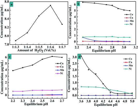
The present work investigated the variation of leaching efficiency with H2SO4 concentration, temperature, reaction time, dosage of H2SO4 and the amount of H2O2. An L16(45) orthogonal experiment was designed and the results are shown in Table 3. The optimal experiment conditions are as follow: reaction time: 2.5 h, reaction temperature: 70 °C, H2SO4 concentration: 3.0 mol L−1, and dosage of H2SO4 solid–liquid ratio: 7 mL g−1. From the orthogonal test data above it is not hard to find that the content of cobalt ions increases with an increase in the dosage of H2O2. In order to further illustrate the relationship between the amount of Co2+ and H2O2, five groups were chosen which operated with the solid–liquid ratio (H2O2/cathode material) of 1.3, 1.4, 1.5, 1.6 and 1.7 under the other optimal conditions and the test results are shown in Fig. 4a. When the H2O2/cathode material ratio is 1![[thin space (1/6-em)]](https://www.rsc.org/images/entities/char_2009.gif) :
:![[thin space (1/6-em)]](https://www.rsc.org/images/entities/char_2009.gif) 1.6, the concentration of cobalt reaches maximum.
1.6, the concentration of cobalt reaches maximum.
| The no. | Factors | |||||
|---|---|---|---|---|---|---|
| t (h) | T (°C) | [Acid] (M) | [H2O2] (vol%) | S![[thin space (1/6-em)]](https://www.rsc.org/images/entities/char_2009.gif) : :![[thin space (1/6-em)]](https://www.rsc.org/images/entities/char_2009.gif) L (g mL−1) L (g mL−1) |
Co (μg mL−1) | |
| 1 | 1.5 | 50 | 2.0 | 1![[thin space (1/6-em)]](https://www.rsc.org/images/entities/char_2009.gif) : :![[thin space (1/6-em)]](https://www.rsc.org/images/entities/char_2009.gif) 1.1 1.1 |
1![[thin space (1/6-em)]](https://www.rsc.org/images/entities/char_2009.gif) : :![[thin space (1/6-em)]](https://www.rsc.org/images/entities/char_2009.gif) 5 5 |
62.3040 |
| 2 | 1.5 | 60 | 2.5 | 1![[thin space (1/6-em)]](https://www.rsc.org/images/entities/char_2009.gif) : :![[thin space (1/6-em)]](https://www.rsc.org/images/entities/char_2009.gif) 1.2 1.2 |
1![[thin space (1/6-em)]](https://www.rsc.org/images/entities/char_2009.gif) : :![[thin space (1/6-em)]](https://www.rsc.org/images/entities/char_2009.gif) 6 6 |
65.4050 |
| 3 | 1.5 | 70 | 3.0 | 1![[thin space (1/6-em)]](https://www.rsc.org/images/entities/char_2009.gif) : :![[thin space (1/6-em)]](https://www.rsc.org/images/entities/char_2009.gif) 1.3 1.3 |
1![[thin space (1/6-em)]](https://www.rsc.org/images/entities/char_2009.gif) : :![[thin space (1/6-em)]](https://www.rsc.org/images/entities/char_2009.gif) 7 7 |
80.7720 |
| 4 | 1.5 | 80 | 3.5 | 1![[thin space (1/6-em)]](https://www.rsc.org/images/entities/char_2009.gif) : :![[thin space (1/6-em)]](https://www.rsc.org/images/entities/char_2009.gif) 1.4 1.4 |
1![[thin space (1/6-em)]](https://www.rsc.org/images/entities/char_2009.gif) : :![[thin space (1/6-em)]](https://www.rsc.org/images/entities/char_2009.gif) 8 8 |
79.0590 |
| 5 | 2.0 | 50 | 2.5 | 1![[thin space (1/6-em)]](https://www.rsc.org/images/entities/char_2009.gif) : :![[thin space (1/6-em)]](https://www.rsc.org/images/entities/char_2009.gif) 1.3 1.3 |
1![[thin space (1/6-em)]](https://www.rsc.org/images/entities/char_2009.gif) : :![[thin space (1/6-em)]](https://www.rsc.org/images/entities/char_2009.gif) 8 8 |
81.2700 |
| 6 | 2.0 | 60 | 2.0 | 1![[thin space (1/6-em)]](https://www.rsc.org/images/entities/char_2009.gif) : :![[thin space (1/6-em)]](https://www.rsc.org/images/entities/char_2009.gif) 1.4 1.4 |
1![[thin space (1/6-em)]](https://www.rsc.org/images/entities/char_2009.gif) : :![[thin space (1/6-em)]](https://www.rsc.org/images/entities/char_2009.gif) 7 7 |
77.6810 |
| 7 | 2.0 | 70 | 3.5 | 1![[thin space (1/6-em)]](https://www.rsc.org/images/entities/char_2009.gif) : :![[thin space (1/6-em)]](https://www.rsc.org/images/entities/char_2009.gif) 1.1 1.1 |
1![[thin space (1/6-em)]](https://www.rsc.org/images/entities/char_2009.gif) : :![[thin space (1/6-em)]](https://www.rsc.org/images/entities/char_2009.gif) 6 6 |
77.5780 |
| 8 | 2.0 | 80 | 3.0 | 1![[thin space (1/6-em)]](https://www.rsc.org/images/entities/char_2009.gif) : :![[thin space (1/6-em)]](https://www.rsc.org/images/entities/char_2009.gif) 1.2 1.2 |
1![[thin space (1/6-em)]](https://www.rsc.org/images/entities/char_2009.gif) : :![[thin space (1/6-em)]](https://www.rsc.org/images/entities/char_2009.gif) 5 5 |
79.8210 |
| 9 | 2.5 | 50 | 3.0 | 1![[thin space (1/6-em)]](https://www.rsc.org/images/entities/char_2009.gif) : :![[thin space (1/6-em)]](https://www.rsc.org/images/entities/char_2009.gif) 1.4 1.4 |
1![[thin space (1/6-em)]](https://www.rsc.org/images/entities/char_2009.gif) : :![[thin space (1/6-em)]](https://www.rsc.org/images/entities/char_2009.gif) 6 6 |
85.2770 |
| 10 | 2.5 | 60 | 3.5 | 1![[thin space (1/6-em)]](https://www.rsc.org/images/entities/char_2009.gif) : :![[thin space (1/6-em)]](https://www.rsc.org/images/entities/char_2009.gif) 1.3 1.3 |
1![[thin space (1/6-em)]](https://www.rsc.org/images/entities/char_2009.gif) : :![[thin space (1/6-em)]](https://www.rsc.org/images/entities/char_2009.gif) 5 5 |
84.6360 |
| 11 | 2.5 | 70 | 2.0 | 1![[thin space (1/6-em)]](https://www.rsc.org/images/entities/char_2009.gif) : :![[thin space (1/6-em)]](https://www.rsc.org/images/entities/char_2009.gif) 1.2 1.2 |
1![[thin space (1/6-em)]](https://www.rsc.org/images/entities/char_2009.gif) : :![[thin space (1/6-em)]](https://www.rsc.org/images/entities/char_2009.gif) 8 8 |
78.2030 |
| 12 | 2.5 | 80 | 2.5 | 1![[thin space (1/6-em)]](https://www.rsc.org/images/entities/char_2009.gif) : :![[thin space (1/6-em)]](https://www.rsc.org/images/entities/char_2009.gif) 1.1 1.1 |
1![[thin space (1/6-em)]](https://www.rsc.org/images/entities/char_2009.gif) : :![[thin space (1/6-em)]](https://www.rsc.org/images/entities/char_2009.gif) 7 7 |
78.0520 |
| 13 | 3.0 | 50 | 3.5 | 1![[thin space (1/6-em)]](https://www.rsc.org/images/entities/char_2009.gif) : :![[thin space (1/6-em)]](https://www.rsc.org/images/entities/char_2009.gif) 1.2 1.2 |
1![[thin space (1/6-em)]](https://www.rsc.org/images/entities/char_2009.gif) : :![[thin space (1/6-em)]](https://www.rsc.org/images/entities/char_2009.gif) 7 7 |
82.2800 |
| 14 | 3.0 | 60 | 3.0 | 1![[thin space (1/6-em)]](https://www.rsc.org/images/entities/char_2009.gif) : :![[thin space (1/6-em)]](https://www.rsc.org/images/entities/char_2009.gif) 1.1 1.1 |
1![[thin space (1/6-em)]](https://www.rsc.org/images/entities/char_2009.gif) : :![[thin space (1/6-em)]](https://www.rsc.org/images/entities/char_2009.gif) 8 8 |
78.4230 |
| 15 | 3.0 | 70 | 2.5 | 1![[thin space (1/6-em)]](https://www.rsc.org/images/entities/char_2009.gif) : :![[thin space (1/6-em)]](https://www.rsc.org/images/entities/char_2009.gif) 1.4 1.4 |
1![[thin space (1/6-em)]](https://www.rsc.org/images/entities/char_2009.gif) : :![[thin space (1/6-em)]](https://www.rsc.org/images/entities/char_2009.gif) 5 5 |
85.5380 |
| 16 | 3.0 | 80 | 2.0 | 1![[thin space (1/6-em)]](https://www.rsc.org/images/entities/char_2009.gif) : :![[thin space (1/6-em)]](https://www.rsc.org/images/entities/char_2009.gif) 1.3 1.3 |
1![[thin space (1/6-em)]](https://www.rsc.org/images/entities/char_2009.gif) : :![[thin space (1/6-em)]](https://www.rsc.org/images/entities/char_2009.gif) 6 6 |
79.5080 |
| I | 287.54 | 311.13 | 297.69 | 296.35 | 312.29 | |
| II | 316.35 | 306.14 | 310.26 | 305.70 | 307.76 | |
| III | 326.16 | 322.09 | 324.29 | 326.18 | 318.78 | |
| IV | 325.74 | 316.44 | 323.55 | 327.55 | 316.95 | |
| i | 71.88 | 77.78 | 74.42 | 74.08 | 78.07 | |
| ii | 79.08 | 76.53 | 77.56 | 76.42 | 76.94 | |
| iii | 81.54 | 80.52 | 81.07 | 81.54 | 79.69 | |
| iv | 81.43 | 79.11 | 80.88 | 81.88 | 79.23 | |
| Extreme deviation | 9.66 | 3.98 | 6.64 | 7.79 | 2.75 | |
| Priority order | Time (h) > H2O2 (vol%) > acid (M) > temperature (°C) > S![[thin space (1/6-em)]](https://www.rsc.org/images/entities/char_2009.gif) : :![[thin space (1/6-em)]](https://www.rsc.org/images/entities/char_2009.gif) L ratio (g mL−1) L ratio (g mL−1) |
|||||
| Optimal level | Time: 2.5 h; H2O2 of dosage: 1.6 mL g−1; acid of concentration: 3.0 mol L−1; temperature: 70 °C; solid–liquid ratio: 7.0 mL g−1 | |||||
3.3. Effect of equilibrium pH on the concentration of metal ions in the leaching solution
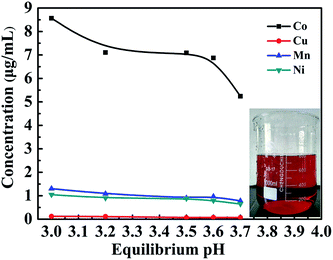
In order to obtain cobalt with the optimal experiment, the relationship between the concentration of metal ions and the pH value was investigated, and the results are shown in Fig. 5. The copper ion concentration changes indistinctively and the concentration of manganese and nickel ions has a tendency to decrease when the pH value is increased from 3.00 to 3.70. When the pH value is increased from 3.00 to 3.25, the cobalt ion concentration falls sharply, however the cobalt ion concentration could remain constant within the pH value between 3.25 and 3.55. In order to maintain a higher cobalt ion concentration and lower the concentrations of manganese ion and nickel ion, the pH value should be adjusted between 3.25 and 3.55.3.4. Study on solvent extraction process
3.5. Cobalt oxalate precipitation analysis
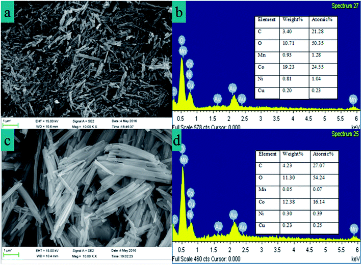
The SEM image (Fig. 6a) of cobalt oxalate was obtained for one D2EHPA extraction and one PC-88A extraction, in which clear crystal structures are observed. In the SEM image from two D2EHPA extractions and one PC-88A extraction, which is shown in Fig. 6c, cobalt oxalate presents regular acicular crystals. The EDX spectra of the cobalt oxalate are shown in Fig. 6b and d, which clearly indicate that the relative content of manganese and copper ions in the precipitation of cobalt oxalate decreases after two D2EHPA extractions.Fig. 7 shows the XRD pattern and FTIR spectra of cobalt oxalate, in which the XRD pattern can be indexed as CoC2O4·2H2O crystals (PDF#25-0250), thus confirming the well crystallized orthorhombic structure. The sharp peaks at 2θ = 19.07°, 22.84°, 30.33° and 30.05° are attributed to the reflections of the (200), (002), (−402) and (021) planes of CoC2O4·2H2O.40,41 From the FTIR spectra, the strong peak at 3370 cm−1 is assigned to the stretching vibration of the (O–H) group, which indicates water of hydration. The peaks at 1621 cm−1 and 1316 cm−1 are assigned to ν(C–O) which is due to the presence of oxalates with all four oxygen atoms.
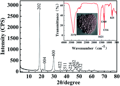 | ||
| Fig. 7 X-ray diffraction pattern of CoC2O4·2H2O precipitate powder. Inset is the FTIR spectrum and photo of cobalt oxalate powder. | ||
The peak at 1360 cm−1 is due to the presence of the carbonyl group.42 The peak at 825 cm−1 is assigned to the δ(O–C–O) band, while the band at 495 cm−1 is assigned to ν(Co–O) and δ(C–C–O),43–46 which indicate that the cobalt oxalate is obtained. The main elements of the cobalt oxalate precipitation were dissolved in an acidic solution and analyzed via ICP spectroscopy to determine the concentrations of cobalt. The results confirmed that the content of cobalt ion is 99.50%. In addition, the contents of the primary elements are cobalt (9.7630 μg mL−1), nickel (0.0279 μg mL−1), manganese (0.0069 μg mL−1), copper (0.0050 μg mL−1) and iron (0.0090 μg mL−1). Aluminum and cadmium were undetected by ICP.
3.6. Environmental and cost assessment
The increase in the usage of lithium batteries will depend on cost reduction and recycling techniques as well as environmental conservation. In the LIBs industry a major portion of the cobalt demand is met by recycled cobalt from spent LIBs, therefore environmental technology will play a very significant role in the pricing of batteries in the future. Reliability, cost, and environmental considerations must be taken into account. Considering the economic aspect, the attraction of recycling lithium-ion batteries depends on the metal market price as well as the electrode technologies used in lithium-ion batteries. Compared with the recovery of lithium, nickel and copper metal, the recycling of cobalt is more meaningful, since cobalt recycling may be economically attractive. From an environmental and health point of view, lithium batteries can represent a significant hazard since these batteries contain hazardous materials. Without proper disposal or recycling, lithium batteries may present potential threats to the environment and human health since they contain organic and inorganic compounds that can explode at high temperature or can pollute the environment. Also, this battery is a potential fire hazard if not discharged completely. Furthermore, some of these inorganic or organic compounds are carcinogenic. Thus, proper recycling methods are very important to the environment.This work focuses on a complete route by the hydrometallurgy method to recycle cobalt from spent LIBs. After pre-treatment, reductive leaching, solvent extraction and selective precipitation, cobalt can be recovered. The leaching solution can be recovered and reused after the extraction and separation of metal ions. By the use of a diluted sulfuric acid washing extraction agent, the purpose of cobalt recycling can be achieved. Theoretically, H2O and O2 are the only by-products in the leaching recovery process. Therefore, this green process may promise a closed-loop route for the sustainable recovery of metals from spent LIBs.
4. Conclusions
This work is focused on recycling cobalt from spent LIBs via a green sustainable method, and the following conclusions were obtained:(1) The optimum leaching conditions are: a contribution of factors affecting size, which are ranked in the order: reaction time 2.5 h, H2O2 dosage 1.6 mL g−1, H2SO4 concentration 3.0 mol L−1, reaction temperature 70 °C, and dosage of H2SO4 7.0 mL g−1.
(2) The extraction of cobalt metal ion is based on the first step leaching experiment, using D2EHPA to extract copper and manganese and PC-88A which can separate nickel and cobalt. The D2EHPA saponification rate was 20%, the saponification PC-88A rate was 30%, sulfonated kerosene accounted for the volume ratio of 70%, and O/A ratio of 1![[thin space (1/6-em)]](https://www.rsc.org/images/entities/char_2009.gif) :
:![[thin space (1/6-em)]](https://www.rsc.org/images/entities/char_2009.gif) 1. The first and second extraction pH of the aqueous solution is 2.70 and 2.60, respectively, using D2EHPA. The pH of the aqueous phase was adjusted to 4.25 using PC-88A.
1. The first and second extraction pH of the aqueous solution is 2.70 and 2.60, respectively, using D2EHPA. The pH of the aqueous phase was adjusted to 4.25 using PC-88A.
(3) Only in this way can a high purity of cobalt be obtained from spent LIBs cathode material. The purity of cobalt ion is up to 99.50% by determining a 0.5 mol L−1 oxalic acid solution.
Acknowledgements
This work was funded by the Major State Basic Research Development Program of China (863 program) (Grant No. SS2015AA034004), and the Sichuan Science and Technology Support Project in China (Project No. 2013GZX0164).References
- K. Richa, C. W. Babbitt, G. Gaustad and X. Wang, Resour., Conserv. Recycl., 2014, 83, 63–76 CrossRef.
- J. Xu, H. R. Thomas, R. W. Francis, K. R. Lum, J. Wang and B. Liang, J. Power Sources, 2008, 177, 512–527 CrossRef CAS.
- S. Al-Thyabat, T. Nakamura, E. Shibata and A. Iizuka, Miner. Eng., 2013, 45, 4–17 CrossRef CAS.
- C.-X. Zu and H. Li, Energy Environ. Sci., 2011, 4, 2614 CAS.
- Z. Y. Ou, J. H. Li and Z. S. W., Environ. Sci.: Processes Impacts, 2015, 17, 1522–1530 CAS.
- J. W. Fergus, J. Power Sources, 2010, 195, 939–954 CrossRef CAS.
- X. Zhang, Y. Xie, X. Lin, H. Li and H. Cao, J. Mater. Cycles Waste Manage., 2013, 15, 420–430 CrossRef CAS.
- T. Georgi-Maschler, B. Friedrich, R. Weyhe, H. Heegn and M. Rutz, J. Power Sources, 2012, 207, 173–182 CrossRef CAS.
- X. P. Chen, C. B. Luo, J. X. Zhang, J. R. Kong and T. Zhou, ACS Sustainable Chem. Eng., 2015, 3, 12 Search PubMed.
- D. A. Bertuol, C. M. Machado, M. L. Silva, C. O. Calgaro, G. L. Dotto and E. H. Tanabe, Waste Manag., 2016, 51, 245–251 CrossRef CAS PubMed.
- J. Ordoñez, E. J. Gago and A. Girard, Renewable Sustainable Energy Rev., 2016, 60, 195–205 CrossRef.
- L. Li, W. Qu, X. Zhang, J. Lu, R. Chen, F. Wu and K. Amine, J. Power Sources, 2015, 282, 544–551 CrossRef CAS.
- A. A. Nayl, M. M. Hamed and S. E. Rizk, J. Taiwan Inst. Chem. Eng., 2015, 55, 119–125 CrossRef CAS.
- H. Zou, E. Gratz, D. Apelian and Y. Wang, Green Chem., 2013, 15, 1183–1191 RSC.
- D. C. R. Espinosa, A. M. Bernardes and J. A. S. Tenório, J. Power Sources, 2004, 135, 311–319 CrossRef CAS.
- D. P. Mantuano, G. Dorella, R. C. A. Elias and M. B. Mansur, J. Power Sources, 2006, 159, 1510–1518 CrossRef CAS.
- N. B. Horeh, S. M. Mousavi and S. A. Shojaosadati, J. Power Sources, 2016, 320, 257–266 CrossRef CAS.
- A. Chagnes and B. Pospiech, J. Chem. Technol. Biotechnol., 2013, 88, 1191–1199 CrossRef CAS.
- L. Li, L. Zhai, X. Zhang, J. Lu, R. Chen, F. Wu and K. Amine, J. Power Sources, 2014, 262, 380–385 CrossRef CAS.
- E. M. S. Barbieri, E. P. C. Lima, S. J. Cantarino, M. F. F. Lelis and M. B. J. G. Freitas, J. Power Sources, 2014, 269, 158–163 CrossRef CAS.
- W. Tang, X. Chen, T. Zhou, H. Duan, Y. Chen and J. Wang, Hydrometallurgy, 2014, 147–148, 210–216 CrossRef CAS.
- M. M. Wang, C. C. Zhang and F. S. Zhang, Waste Manag., 2016, 51, 239–244 CrossRef CAS PubMed.
- K. Provazi, B. A. Campos, D. C. Espinosa and J. A. Tenorio, Waste Manag., 2011, 31, 59–64 CrossRef CAS PubMed.
- G. Granata, F. Pagnanelli, E. Moscardini, Z. Takacova, T. Havlik and L. Toro, J. Power Sources, 2012, 212, 205–211 CrossRef CAS.
- G. Dorella and M. B. Mansur, J. Power Sources, 2007, 170, 210–215 CrossRef CAS.
- L. Chen, X. Tang, Y. Zhang, L. Li, Z. Zeng and Y. Zhang, Hydrometallurgy, 2011, 108, 80–86 CrossRef CAS.
- X. Chen, B. Xu, T. Zhou, D. Liu, H. Hu and S. Fan, Sep. Purif. Technol., 2015, 144, 197–205 CrossRef CAS.
- X. Zeng, J. Li and B. Shen, J. Hazard. Mater., 2015, 295, 112–118 CrossRef CAS PubMed.
- P. Meshram, B. D. Pandey and T. R. Mankhand, Hydrometallurgy, 2014, 150, 192–208 CrossRef CAS.
- Y. Pranolo, W. Zhang and C. Y. Cheng, Hydrometallurgy, 2010, 102, 37–42 CrossRef CAS.
- K. C. Nathsarma and N. Devi, Hydrometallurgy, 2006, 84, 149–154 CrossRef CAS.
- P. Zhang, T. Yokoyama, O. Itabashi, T. M. Suzuki and K. Inoue, Hydrometallurgy, 1998, 47(2–3), 259–271 CrossRef CAS.
- D. Das, V. A. Juvekar, V. H. Rupawate, K. Ramprasad and R. Bhattacharya, Hydrometallurgy, 2015, 152, 129–138 CrossRef CAS.
- X. Chen, Y. Chen, T. Zhou, D. Liu, H. Hu and S. Fan, Waste Manag., 2015, 38, 349–356 CrossRef CAS PubMed.
- K. Sarangi, B. R. Reddy and R. P. Das, Hydrometallurgy, 1999, 52(3), 253–265 CrossRef CAS.
- J. Nan, D. Han and X. Zuo, J. Power Sources, 2005, 152(1), 278–284 CrossRef CAS.
- Y. Guo, F. Li, H. Zhu, G. Li, J. Huang and W. He, Waste Manag., 2016, 51, 227–233 CrossRef CAS PubMed.
- G. P. Nayaka, J. Manjanna, K. V. Pai, R. Vadavi, S. J. Keny and V. S. Tripathi, Hydrometallurgy, 2015, 151, 73–77 CrossRef CAS.
- L. Li, J. B. Dunn, X. X. Zhang, L. Gaines, R. J. Chen, F. Wu and K. Amine, J. Power Sources, 2013, 233, 180–189 CrossRef CAS.
- P. Meshram, B. D. Pandey and T. R. Mankhand, Waste Manag., 2015, 45, 306–313 CrossRef CAS PubMed.
- G. Cheng, C. Si, J. Zhang, Y. Wang, W. Yang, C. Dong and Z. Zhang, J. Power Sources, 2016, 312, 184–191 CrossRef CAS.
- G. P. Nayaka, K. V. Pai, G. Santhosh and J. Manjanna, J. Environ. Chem. Eng., 2016, 4, 2378–2383 CrossRef CAS.
- L. Sun and K. Qiu, J. Hazard. Mater., 2011, 194, 378–384 CrossRef CAS PubMed.
- Y. Deng, X. Xiong, J. P. Zou, L. Deng and M. J. Tu, J. Alloys Compd., 2015, 618, 497–503 CrossRef CAS.
- X. Wang, G. Gaustad, C. W. Babbitt and K. Richa, Resour., Conserv. Recycl., 2014, 83, 53–62 CrossRef.
- L. Sun and K. Qiu, Waste Manag., 2012, 32, 1575–1582 CrossRef CAS PubMed.
| This journal is © The Royal Society of Chemistry 2016 |

