
Single-walled carbon nanotubes/polyaniline-coated polyester thermoelectric textile with good interface stability prepared by ultrasonic induction
Peng Lia,
Yang Guoa,
Jiuke Mua,
Hongzhi Wang*a,
Qinghong Zhanga and
Yaogang Li*b
aState Key Laboratory for Modification of Chemical Fibers and Polymer Materials, Donghua University, 2999 North Renmin Road, Songjiang, Shanghai 201620, P. R. China. E-mail: wanghz@dhu.edu.cn
bEngineering Research Center of Advanced Glasses Manufacturing Technology, MOE, Donghua University, Shanghai 201620, P. R. China. E-mail: yaogang_li@dhu.edu.cn
First published on 8th September 2016
Abstract
Wearable electronic devices such as medical sensors, hearing aids and wristwatches can run on power of μW levels. Thermoelectric (TE) generators have the potential to provide power to wearable electronic devices, because they can effectively convert body heat into electrical energy. This study presents a flexible TE generator by applying single-walled carbon nanotube/polyaniline (SWNT/PANI) composites to polyesters, and it was found that ultrasonic induction can enhance the interfacial stability between SWNT/PANI composites and polyesters. The flexible TE generator can generate a TE voltage of 3.82 mV at a temperature difference of 115 K. Moreover, the TE generator can supply a maximum output power of 48.0 nW to the load at a temperature difference of 75 K. In addition to good flexibility and ventilation, the SWNT/PANI textile TE generator displays no change in performance on repeated bending for 150 cycles with a radius of 5 mm, which is important for wearable electronic devices.
1. Introduction
Small, wearable electronic devices that can be worn directly on the soft and curved human body play an increasingly important role in daily life.1,12 Small devices such as medical sensors, hearing aids and wristwatches can run on very low power (in the range of μW).2 However, current power generators such as batteries are heavy and rigid. Furthermore, as well as the drawback of requiring frequent replacement, batteries contain electrolytes that are mostly harmful to the body and environment.Naturally, some power generators such as solar cells and thermoelectric (TE) power generators are expected to act as new renewable power generators. Given that solar cells cannot work without sunlight, TE generators, as next-generation wearable power generators, are attracting the attention of researchers. After all, TE power generators can efficiently convert temperature differences into electrical energy via the Seebeck effect.3,4,11,21,23
Recently, Sun et al. demonstrated a glass fabric-based TE generator,12 Lee et al. described a knitted TE textile based on electrospun polymer nanofiber cores,37 and Lu et al. presented a silk fabric-based wearable thermoelectric generator.38 Although typical semiconductor TE materials (such as Bi2Te3 and Sb2Te3) have a high power output, they are not flexible or lightweight enough, and some of them are even slightly toxic.8 Therefore, it is usually difficult to fabricate a wearable power generator using semiconductor TE materials. Polyaniline (PANI), which is one of the most promising organic TE materials, has the advantages of a simple synthesis process, excellent chemical stability and inexpensive raw materials.5,6,8,14 In comparison with semiconductor TE materials, however, the low conductivity and mediocre Seebeck coefficient of PANI hinder the improvement of its TE properties.12 With respect to PANI, the carrier mobility is the most important factor for improving both the electrical conductivity and the Seebeck coefficient.10 However, the disordered chain arrangement and twisted chain conformation of PANI result in an increased barrier to both interchain hopping and intrachain hopping, which therefore reduces carrier mobility.9 Toshima et al. reported that the ordering of the chain structure of PANI has been improved by the self-assembly of PANI on the surface of SWNTs via strong π–π interactions between the surface of the SWNTs and PANI molecules.13,16,18,34
As well as excellent TE properties and flexibility, amenity and ventilation are also important for small power generators. Recently, Du et al. reported a TE textile fabricated by applying poly(3,4-ethylenedioxythiophene)![[thin space (1/6-em)]](https://www.rsc.org/images/entities/char_2009.gif) :poly(4-styrenesulfonate) (PEDOT:PSS) to polyesters, which did not display an obvious decline in amenity and ventilation.7 However, there still remains some progress to be made regarding the requirements for small power generators owing to the low electrical conductivity of PEDOT:PSS. In comparison with PEDOT:PSS, SWNT/PANI has higher electrical conductivity, which is more advantageous for the improvement of the TE properties of the textiles.
:poly(4-styrenesulfonate) (PEDOT:PSS) to polyesters, which did not display an obvious decline in amenity and ventilation.7 However, there still remains some progress to be made regarding the requirements for small power generators owing to the low electrical conductivity of PEDOT:PSS. In comparison with PEDOT:PSS, SWNT/PANI has higher electrical conductivity, which is more advantageous for the improvement of the TE properties of the textiles.
Because wearable power generators require high mechanical and electrical stabilities under repeated tensile and compressive strains,12 high stability of the interface between SWNT/PANI and polyesters is indispensable. However, on account of the shortage of structure defects in SWNTs,7 poor interfacial stability is achieved between SWNT/PANI and polyesters via general processes such as dip coating and heating treatment. It is therefore essential to develop a new way of increasing the interfacial stability between SWNT/PANI and polyesters.
In this paper, a flexible TE device was prepared by applying SWNT/PANI composites to polyesters via ultrasonic induction and then connecting two slices of strips in series. Owing to the treatment by ultrasonic induction, the textiles coated with SWNT/PANI possess good interfacial stability and display no change in performance on repeated bending for up to 150 cycles with a radius of 5 mm. In addition to excellent TE properties, this device possesses good flexibility and ventilation, which are important for wearable electronic devices.
2. Materials and methods
2.1 Preparation of SWNT/PANI solution
Initially, 60 mL of 1 M HCl solution, which contained 15 mg SWNTs (SWNT ≥ 95%, the length ranged between 5 and 30 μm and the diameter ranged between 1 and 2 nm) and 45 mg sodium 4-dodecylbenzenesulfonate (SDBS, purity: 97%), was prepared and then sonicated by an ultrasonic cell disruptor for 2 h at room temperature. Different masses of aniline monomer (1.0216 g mL−1) were added to the above solution to prepare aniline dispersions of various molar concentrations (0 mM, 1.83 mM, 2.74 mM, and 5.48 mM). Then, a certain amount of aniline monomer was added to 60 mL of 1 M HCl solution without SWNTs to prepare a 5.48 mM aniline dispersion. The mixed dispersion was sonicated for 30 min and then put into an ice water bath and magnetically stirred. Next, ammonium persulphate (APS, Mw: 228 g mol−1) was dissolved in 5 mL of 1 M HCl solution and slowly added dropwise to the stirred dispersion. The reaction was continued for 8 h after the suspension became green.2.2 SWNT/PANI composites coating treatment
Polyesters were immersed in 5 wt% NaOH solution at 75 °C for 10 min. Then, the as-treated polyesters were immersed in distilled water at 75 °C for 10 min to remove residual NaOH ions and other unwanted products.The as-treated polyesters were immersed in SWNT/PANI solution, sonicated for 2 h, and then dried at 60 °C for 12 h. Then, the above steps were repeated twice.
2.3 Fabrication of TE generators
Firstly, untreated polyesters were chosen as a flexible base and cut into strips (length × width, 5 cm × 2 cm). Then, textiles coated with SWNT/PANI were cut into two slices of strips (length × width, 4 cm × 0.6 cm) and then fixed on the polyesters. Next, the two slices were connected in series because SWNT/PANI was a p-type TE material. To reduce the contact resistance of the TE device, silver wires and silver paint were used as conductive connections. Finally, copper foil tape was fixed to the connection point to increase the stability of the entire device.2.4 Characterization and measurements
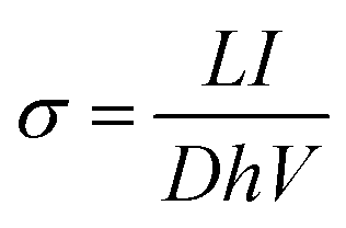
The surface morphology of the as-prepared samples was observed using a JSM-6700F FESEM. Raman spectra were recorded using a Renishaw in plus laser Raman spectrometer with λexc = 532 nm. Fourier transform infrared (FT-IR) spectra were recorded on a Nicolet 6700. Digital photos were taken with a CCD video camera (PowerShot G10, Canon). Bending tests were carried out with a mechanical motor (homemade device).The conductivity was measured in-plane by a Zahner electrochemical workstation (Zennium CIMPS-1). The conductivity was defined as:
 | (1) |
3. Results and discussion
Fig. 1 shows the in situ polymerization process of SWNT/PANI composites. Firstly, SWNTs and aniline molecules were sonicated and then stirred. Naturally, the aniline molecules were adsorbed onto the surface of the nanotubes by the formation of a charge transfer complex.15 Next, the aniline molecules started to undergo oxidation polymerization after the addition of APS. Finally, PANI molecules were tightly bound to the surface of the SWNTs owing to strong π–π interactions and then grew along the hexagonal lattice of the SWNTs, which led to an expanded molecular conformation and a good order of chain packing.16,26 The ordered molecular structure results in a reduction in the number of π–π conjugation defects in the polymer backbone, which then increases the effective degree of electron delocalization and reduces the hopping barrier, which therefore increases the carrier mobility.9 Moreover, the interfacial barrier between PANI and SWNTs can filter low-energy carriers and enhance the scattering effect of long-wave phonons.17 | ||
| Fig. 1 In situ polymerization process of SWNT/PANI composites. | ||
Fig. 2 shows the FT-IR spectra of SWNT/PANI composites with different initial aniline concentrations. It is clear that the FT-IR spectra of SWNT/PANI composites and pure PANI are similar. For pure PANI, the peaks at 1572 cm−1 and 1484 cm−1 correspond to the stretching vibrations of quinone and benzene rings. Moreover, the peaks at 1297 cm−1 and 1143 cm−1 could be assigned to C–H stretching vibrations and C–H in-plane bending.19,20 For pure SWNTs, the peak at 1629 cm−1 was attributed to C![[double bond, length as m-dash]](https://www.rsc.org/images/entities/char_e001.gif) C stretching vibrations.22 With an increase in the content of SWNTs in SWNT/PANI composites, the peak at 1572 cm−1 exhibited a red shift and the peak at 1484 cm−1 exhibited a blue shift, as a result of interactions between delocalized π-bonds on the surface of SWNTs and the conjugated structure of PANI. Moreover, the peak at 1484 cm−1 increased in intensity and the peak at 1572 cm−1 gradually decreased with an increase in the content of SWNTs. In fact, the change in the infrared peak intensity indicates a decrease in the concentration of quinonoid units and an increase in the concentration of benzenoid units when the content of SWNTs in SWNT/PANI composites increases.24
C stretching vibrations.22 With an increase in the content of SWNTs in SWNT/PANI composites, the peak at 1572 cm−1 exhibited a red shift and the peak at 1484 cm−1 exhibited a blue shift, as a result of interactions between delocalized π-bonds on the surface of SWNTs and the conjugated structure of PANI. Moreover, the peak at 1484 cm−1 increased in intensity and the peak at 1572 cm−1 gradually decreased with an increase in the content of SWNTs. In fact, the change in the infrared peak intensity indicates a decrease in the concentration of quinonoid units and an increase in the concentration of benzenoid units when the content of SWNTs in SWNT/PANI composites increases.24
 | ||
| Fig. 2 FT-IR spectra of SWNT/PANI composites with different initial aniline concentrations. | ||
Fig. 3 shows scanning electron microscopy images of untreated polyester (a) and polyester treated with NaOH solution (b). The insets of (a) and (b) show images of the contact angles. A smooth surface and a flawless structure can be observed in Fig. 3(a), because polyethylene glycol terephthalate, which is the main component of polyesters, has few hydrophilic functional groups. After treatment with NaOH solution, the surface of polyesters became rough and some micropores appeared, in consequence of the corrosive effect of NaOH solution (Fig. 3(b)). Although the strength of fibers decreased slightly, the micropores on the surface of polyesters and their increased hydrophilicity induced polyesters to bind to SWNT/PANI tightly. After treatment with NaOH solution, the crystallinity of polyesters decreased on account of their hydrolysis. Then, the amount of hydrophilic functional groups in polyesters increased and their hydrophilicity increased markedly, which resulted in a change in the contact angle of polyesters (see insets of Fig. 3(a) and (b)).
 | ||
| Fig. 3 SEM images of (a) untreated polyester and (b) polyester treated with NaOH solution. The insets of (a) and (b) show images of the contact angles. | ||
Fig. 4 shows typical SEM images of textiles coated with SWNT/PANI by ultrasonic induction. It can be observed from these micrographs that the surfaces of the textiles were smooth after being treated three times by ultrasonic induction and the textiles were almost coated with SWNT/PANI (Fig. 4(a) and (b)). On the surface of fibers, SWNTs acted as a frame and particles of PANI were distributed in the frame randomly (Fig. 4(c)). Actually, SWNTs acted as a framework to increase carrier mobility in the SWNT/PANI composites; on the other hand, PANI filled all the gaps in the composites that corresponded to effective scattering centers of phonons.17
 | ||
| Fig. 4 SEM images of textiles coated with SWNT/PANI composites by ultrasonic induction: (a) low magnification, (b) high magnification and (c) partially enlarged view. (d) Bending test on textiles coated with SWNT/PANI. | ||
In order to test the stability of the interface between SWNT/PANI composites and polyesters, a bending test was carried out using a mechanical motor (homemade device). As shown in Fig. 4(d), after 150 bending cycles with a radius of 5 mm, the rate of decline in the electrical conductivity of textiles treated by ultrasonic induction remained less than 10%. However, the rates of decline for textiles treated by heating treatment and dip coating were 45% and 42%, respectively. Therefore, the results of the bending test demonstrated that SWNT/PANI composites were tightly bound to polyesters after treatment by ultrasonic induction, and it was difficult for SWNT/PANI composites to become separated from polyesters.
After treatment with NaOH solution, some functional groups (OH−) were introduced onto the surface of polyesters, and the SWNT/PANI solution contained H+ because of residues of the 1 M HCl solution. Therefore, when polyesters were immersed in SWNT/PANI solution, some SWNT/PANI particles would approach the surface of polyesters as a result of attraction between different ions. When the solution was sonicated, microbubbles in solution would vibrate and grow under the effect of the sound field (Fig. 5(a)). When the sound pressure reached a certain value, the microbubbles would suddenly break up and then an impact pressure of thousands of times standard atmospheric pressure was produced.33
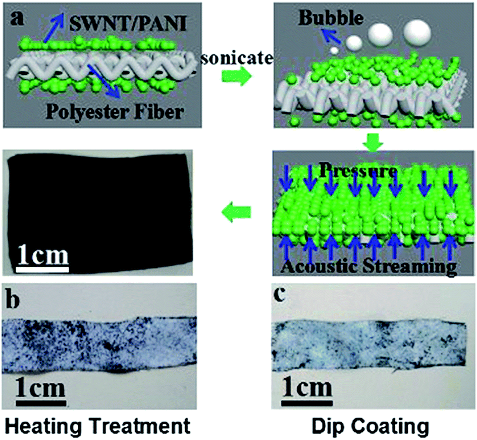 | ||
| Fig. 5 Process of coating SWNT/PANI composites on polyesters (a). Digital photos of textiles after heating treatment (b) and dip coating (c), respectively. | ||
As a result of pressure and acoustic streaming, the surface of polyesters was evenly coated with SWNT/PANI composites after treatment by ultrasonic induction (Fig. 5(a)). In comparison, when polyesters were treated by dip coating or heating treatment, there was not enough external force to compel polyesters to bind to SWNT/PANI tightly. Therefore, the surfaces of polyesters were coated with few SWNT/PANI composites (Fig. 5(b) and (c)).
Fig. 6(a) shows the temperature dependence of the electrical conductivity of textiles coated with SWNT/PANI composites with different initial aniline concentrations. At room temperature, the electrical conductivity of textiles coated with SWNT/PANI composite (1.83 mM) reached 2272.1 S m−1, which was three orders of magnitude greater than that of textiles coated with pure PANI (3.5 S m−1). With an increase in the initial aniline concentration, the electrical conductivity of textiles coated with SWNT/PANI gradually declined because of the relatively low conductivity of PANI. Moreover, the electrical conductivity of textiles coated with pure SWNTs reached 408.6 S m−1, which was only a quarter of that of textiles coated with SWNT/PANI composites (1.83 mM). On account of the shortage of structure defects in SWNTs, the coating ratio of pure SWNTs was lower than that of SWNT/PANI; therefore, the electrical conductivity of textiles coated with SWNTs was lower than that of textiles coated with SWNT/PANI. In addition, for textiles coated with SWNT/PANI composites and pure PANI, the electrical conductivity was reduced by a small margin with a rise in temperature (Fig. 6(a)). This was a result of the fact that some volatile species and moisture escaped from textiles coated with SWNT/PANI composites or pure PANI below 420 K.25 Instead, owing to an increase in carrier concentration,26 the electrical conductivity of textiles coated with pure SWNTs increased slightly (from 408.6 S m−1 to 463.3 S m−1) with a rise in temperature.
 | ||
| Fig. 6 Temperature dependence of electrical conductivity (a), Seebeck coefficient (b), and power factor (c) of textiles coated with SWNT/PANI composites with different initial aniline concentrations; thermal conductivity of textiles coated with SWNT/PANI composites with different initial aniline concentrations (d). | ||
The disordered chain arrangement and twisted chain conformation of PANI will reduce the carrier mobility, which is the most important factor for the Seebeck coefficient.9 Therefore, the Seebeck coefficient of textiles coated with pure PANI (∼2 μV K−1) was one order of magnitude less than that of textiles coated with SWNT/PANI composites (∼12 μV K−1). For textiles coated with SWNT/PANI composites, the power factor increased from 0.09 μW m−1 K−2 to 0.28 μW m−1 K−2 while the initial concentration of aniline decreased from 5.48 mM to 1.83 mM (Fig. 6(c)), because the addition of SWNTs increased the carrier mobility and thus increased the Seebeck coefficient.
The thermal conductivities of pure PANI and pure SWNTs were already reported to be ∼0.2 W m−1 K−1 and ∼1000 W m−1 K−1.27,28 In order to further reduce the thermal conductivity of composites, PANI was added to SWNTs to act as a crystal lattice to enhance the effect of phonon scattering.26 It was found that the thermal conductivity gradually declined from 5.47 W m−1 K−1 to 4.80 W m−1 K−1 with an increase in the content of PANI (Fig. 6(d)). Moreover, polyesters used as the substrate could further reduce the thermal conductivity of the entire textile.
Fig. 7(a) illustrates the assembly process of the textile TE generator. Furthermore, this TE device could bend through large angles, which indicates that this device possesses high flexibility, which is important for wearable electronic devices (Fig. 7(b)). The plan area of the TE device was 0.001 m2 (length × width, 5 cm × 2 cm) and the weight of the device was only about 0.4 g (Fig. 7(c)). The good flexibility and light weight of this TE device can meet the requirements for wearable power devices.
 | ||
| Fig. 7 Assembly process of textile TE generator (a); display of flexibility of TE device fabricated from two slices of p-type textiles (length × width, 4 cm × 0.6 cm) (b); display of weight of device (length × width, 5 cm × 2 cm) (c). | ||
When one end of the device was heated and thus a temperature difference was generated between the two ends of the device, it worked and supplied energy to the load (Fig. 8(a)). The voltage contribution is determined by the Seebeck coefficients of the materials and the current contribution is determined by the internal resistance of the device.21 The TE device that was fabricated from p-type textiles coated with SWNT/PANI composites (2.74 mM) generated a TE voltage output of 3.82 mV at a temperature difference of 115 K (Fig. 8(b)). It could also generate a maximum TE current output of 66.45 μA at a temperature difference of 115 K (Fig. 8(c)). Moreover, textiles coated with pure SWNTs generated a TE voltage output of 4.40 mV and a TE current output of 2.76 μA at a temperature difference of 115 K, whereas textiles coated with pure PANI reached a voltage of around 0.91 mV and a current of 7.20 μA at a temperature difference of 115 K. At a temperature difference of 75 K, a device fabricated from SWNT/PANI could generate a power output of 47 nW (Fig. 8(d)), which was much higher than that (∼3 nW) of a device fabricated from PEDOT:PSS.7
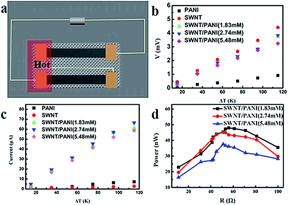 | ||
| Fig. 8 Diagram of TE device fabricated from two slices of textiles (a); output voltage (b); output current (c); output power (d). | ||
A bending test was carried out using a mechanical motor (homemade device) to characterize the flexibility of TE devices fabricated from SWNT/PANI textiles. The rate of decline in the output voltage and output power was less than 10% (6% and 9%, respectively) after 150 bending cycles with a radius of 5 mm (Fig. 9(a) and (b)).
 | ||
| Fig. 9 Bending test on TE properties of devices fabricated from SWNT/PANI textiles: (a) output voltage; (b) output power. | ||
For an adult with a height of 1.7 m and a weight of 70 kg, apart from the surface of the head, neck, feet and hands, the area of the body surface is ∼1.47 m2.35,36 After being folded once, one side of the TE device fabricated from SWNT/PANI textiles is close to the body surface and the other side is exposed to the environment, and the plan area of the TE device is about 0.0005 m2. Assuming that there exists a temperature difference of 75 K between the body and the environment, the calculated value of Pmax would reach 138.18 μW, which could meet the needs of wearable electronic devices such as medical sensors, hearing aids and wristwatches. Actually, the normal temperature difference between the body and the environment is about 0–50 K; therefore, more intensive research is needed to increase the power output of SWNT/PANI textile TE devices.
4. Conclusions
In summary, a TE textile was prepared via applying SWNT/PANI composites to polyesters by ultrasonic induction. In comparison with textiles treated by dip coating or heating treatment, textiles treated by ultrasonic induction exhibited better interfacial stability and displayed no change in performance on repeated bending for up to 150 cycles at a bending radius of as low as 5 mm. Moreover, the maximum power factor (S2σ) of the TE textiles was ∼0.28 μW m−1 K−2 when the initial aniline concentration was 1.83 mM, which was more than two orders of magnitude higher than that of textiles coated with pure PANI. When two slices of textiles (length × width, 4 cm × 0.6 cm) (1.83 mM) were assembled into a TE device in series, the TE device could generate a maximum TE voltage output of 3.82 mV at a temperature difference of 115 K and a power output of 48.0 nW at a temperature difference of 75 K. The excellent interfacial stability, flexibility, light weight and good TE properties of SWNT/PANI TE textiles are highly desirable for developing wearable electronic devices.Acknowledgements
We gratefully acknowledge the financial support by the Natural Science Foundation of China (No. 61674028), the Shanghai Natural Science Foundation (15ZR1401200), the Program for Professor of Special Appointment (Eastern Scholar) at Shanghai Institutions of Higher Learning, Program of Shanghai Academic Research Leader (16XD1400100), the Program of Introducing Talents of Discipline to Universities (No. 111-2-04) and the Fundamental Research Funds for the Central Universities (2232014A3-06, 16D310612).Notes and references
- X. M. Tao, Wearable electronics and photonics, Woodhead Publishing Limited, 2005 Search PubMed.
- J. Weber, K. Potje-Kamloth, F. Haase and P. Detemple, Sens. Actuators, A, 2006, 132, 325–330 CrossRef CAS.
- G. J. Snyder and E. S. Toberer, Nat. Mater., 2008, 7, 105–114 CrossRef CAS PubMed.
- M. Zebarjadi, K. Esfarjani and M. S. Dresselhaus, Energy Environ. Sci., 2012, 5, 5147–5162 Search PubMed.
- N. Dubey and M. Leclerc, J. Polym. Sci., Part B: Polym. Phys., 2011, 49, 467–475 CrossRef CAS.
- H. Yan, T. Ohta and N. Toshima, Mater. Eng., 2001, 286, 139–142 CAS.
- Y. Du, K. Cai, S. Chen, H. Wang, S. Z. Shen, R. Donelson and T. Lin, Sci. Rep., 2015, 5, 6411–6416 CrossRef CAS PubMed.
- Q. Zhang, Y. Sun, W. Xu and D. Zhu, Adv. Mater., 2014, 26, 6829–6851 CrossRef CAS PubMed.
- Y. Hiroshige, M. Ookawa and N. Toshima, Synth. Met., 2006, 156, 1341–1347 CrossRef CAS.
- S. C. Liufu, L. D. Chen, Q. Yao and C. F. Wang, Appl. Phys. Lett., 2007, 90, 112106 CrossRef.
- J. Mu, C. Hou, H. Wang, Y. Li and Q. Zhang, Carbon, 2015, 95, 150–156 CrossRef CAS.
- S. J. Kim, J. H. We and B. J. Cho, Energy Environ. Sci., 2014, 7, 1959–1965 CAS.
- N. Toshima, K. Oshima, H. Anno and T. Nishinaka, Adv. Mater., 2015, 27, 2246–2251 CrossRef CAS PubMed.
- C. Cho, B. Stevens, J. H. Hsu and R. Bureau, Adv. Mater., 2015, 27, 2996–3001 CrossRef CAS PubMed.
- Y. Sun, S. R. Wilson and D. I. Schuster, J. Am. Chem. Soc., 2001, 123, 5348–5349 CrossRef CAS PubMed.
- R. Sainz, A. M. Benito, M. T. Martínez and J. F. Galindo, Adv. Mater., 2005, 17, 278–281 CrossRef CAS.
- B. Poudel, Q. Hao, Y. Ma, Y. Lan, A. Minnich and B. Yu, Science, 2008, 320, 634–638 CrossRef CAS PubMed.
- J. Liu, J. Sun and L. Gao, Nanoscale, 2011, 3, 3616–3619 RSC.
- X. Yao, X. Kou, J. Qiu and M. Moloney, RSC Adv., 2016, 6, 35378–35386 RSC.
- L. Q. Xu, Y. L. Liu, K. G. Neoh, E. T. Kang and G. D. Fu, Macromol. Rapid Commun., 2011, 32, 684–688 CrossRef CAS PubMed.
- C. A. Hewitt, A. B. Kaiser, S. Roth, M. Craps and R. Czerw, Nano Lett., 2012, 12, 1307–1310 CrossRef CAS PubMed.
- A. M. Shanmugharaj, J. H. Bae, K. Y. Lee and W. H. Noh, Compos. Sci. Technol., 2007, 67, 1813–1822 CrossRef CAS.
- W. Zhao, S. Fan, N. Xiao, D. Liu, Y. Y. Tay and C. Yu, Energy Environ. Sci., 2012, 5, 5364–5369 CAS.
- Q. Yao, Q. Wang and L. Wang, Energy Environ. Sci., 2014, 7, 3801–3807 CAS.
- J. Xiang and L. T. Drzal, Polymer, 2012, 53, 4202–4210 CrossRef CAS.
- Q. Yao, L. Chen, W. Zhang, S. Liufu and X. Chen, ACS Nano, 2010, 4, 2445–2451 CrossRef CAS PubMed.
- P. B. Kaul, K. A. Day and A. R. Abramson, J. Appl. Phys., 2007, 101, 083507 CrossRef.
- J. Che, T. Cagin and W. A. Goddard III, Nanotechnology, 2000, 11, 65–69 CrossRef CAS.
- C. Yu, A. Murali, K. Choi and Y. Ryu, Energy Environ. Sci., 2012, 5, 9481–9486 CAS.
- W. Lee, C. T. Hong, O. H. Kwon, Y. Yoo, Y. H. Kang, J. Y. Lee and K. S. Jang, ACS Appl. Mater. Interfaces, 2015, 7, 6550–6556 CAS.
- Y. Guo, J. K. Mu, C. Y. Hou, H. Z. Wang, Q. H. Zhang and Y. G. Li, Carbon, 2016, 107, 146–153 CrossRef CAS.
- G. Xin, H. Sun, T. Hu, H. R. Fard, X. Sun, N. Koratkar and J. Lian, Adv. Mater., 2014, 26, 4521–4526 CrossRef CAS PubMed.
- P. M. Garcia and B. Bradford, Hydrokinetic using the cleaning of exchanger tubes and pipes, Proceeding of the 10th American Water Jet Conference, Houston Texas, Chicogo, Dearborn, 1999 Search PubMed.
- H. A. Park, S. Liu, P. A. Salvador, G. S. Rohrer and M. F. Islam, RSC Adv., 2016, 6, 22285–22294 RSC.
- G. B. Haycock, G. J. Schwartz and D. H. Wisotsky, J. Pediatr., 1978, 93, 62–66 CrossRef CAS PubMed.
- P. Tikuisis, P. Meunier and C. Jubenville, Eur. J. Appl. Physiol, 2001, 85, 264–271 CrossRef CAS PubMed.
- J. A. Lee, A. E. Aliev and J. S. Bykova, Adv. Mater., 2016, 28, 5038–5044 CrossRef CAS PubMed.
- Z. Lu, H. Zhang, C. Mao and C. M. Li, Appl. Energy, 2016, 164, 57–63 CrossRef CAS.
| This journal is © The Royal Society of Chemistry 2016 |