Control of SrO buffer-layer formation on Si(001) using the pulsed-laser deposition technique

Z. Jovanović*ab, M. Spreitzer*a, U. Gabora and D. Suvorova
aAdvanced Materials Department, Jožef Stefan Institute, Jamova 39, 1000 Ljubljana, Slovenia. E-mail: matjaz.spreitzer@ijs.si
bLaboratory of Physics, Vinča Institute of Nuclear Sciences, University of Belgrade, P.O. Box 522, 11000 Belgrade, Serbia. E-mail: zjovanovic@vinca.rs

Received 23rd June 2016 , Accepted 21st August 2016

First published on 22nd August 2016


Abstract

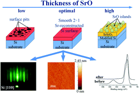
The deoxidation and passivation of a silicon surface represents one of the most important steps in the successful integration of functional oxides with silicon. Due to its reactivity and dissimilar properties with respect to oxides, silicon surfaces are conditioned using various buffer systems. Despite the quality of the resulting surface, these Sr-based buffers have not been commercialized because of the reactivity of the metallic Sr. SrO has demonstrated properties that are competitive with metallic Sr, but a successful integration with silicon has not yet been proven. In the present study we have determined the optimal pulsed-laser deposition (PLD) conditions for the SrO-induced deoxidation of a silicon surface, which results in a 2 × 1 reconstructed surface. Additionally, the as-prepared surface is oxide-free and atomically flat. The results show that the amount of SrO plays the most critical role in the optimization of the whole process. Deposited in batch mode, the amount of SrO affects the morphologies of the surfaces, which change from a dimerized surface to SrO islands and a polycrystalline layer in the final stage. However, in the case of an insufficient amount of deposited SrO, pits are formed on the surface, drastically increasing its roughness. The successful optimization of the PLD conditions for the formation of a SrO buffer layer opens a new pathway for interfacing oxides with silicon.


Introduction

In recent years there has been an increasing interest in the epitaxial integration of functional oxides with silicon due to the unique properties arising from their co-action.1–3 However, the epitaxial growth of functional oxides on silicon is an intrinsically challenging process due to the dissimilar properties and the mutual reactivity of the materials,4 which is additionally complicated by the presence of a surface layer of amorphous SiO2. Therefore, prior to growth, the removal of the native oxide from the silicon substrate is required. The process of deoxidation for silicon surfaces evolved from wet-chemistry methods5 to UHV procedures, where Sr and SrO have proved to be especially useful by decreasing the deoxidation temperature6,7 and limiting the reactivity of the interface with respect to oxygen.8,9 Previously, the molecular beam epitaxy (MBE)6,7,10–17 and atomic layer deposition (ALD)18,19 methods were the only in situ UHV methods capable of deoxidation and the formation of a Sr-reconstructed silicon surface. In our recent study, the 2 × 1 reconstruction of a silicon surface was achieved with the help of SrO deposited using the pulsed-laser deposition (PLD) method.20 However, the formation of a 2 × 1 reconstructed silicon surface was always accompanied by surface roughening and the formation of SiC.

The results clearly indicated the need for an optimization of the experimental conditions in order to achieve control over the Si surface's reconstruction and quality. Therefore, the present study investigates the influence of the deposition conditions on the formation of a Sr-reconstructed silicon surface. In order to do this, the deposition atmosphere and temperature, the pulsing regime (deposition rate and fluence) as well as the amount of SrO, as the deoxidizing agent, were examined. The obtained results emphasize the set of experimental conditions for the PLD method that allow the realization of a smooth, 2 × 1 Sr-reconstructed silicon surface suitable for the epitaxial integration of functional oxides.

Experimental

The 5 mm × 5 mm B-doped Si(100) substrates (Si-Mat, Germany) were ultrasonically cleaned in acetone for 3 min, thoroughly rinsed with EtOH and blow-dried with a N2 gun (referred to as initial cleaning). Next, the substrates were glued to the stainless-steel sample plate using silver paste (Leitsilber 200, TedPella, Inc., USA) and heated up in air (∼120 °C) to remove the organic solvent. Subsequently, the sample was inserted into the PLD chamber (Twente Solid State Technology, Netherlands) and degassed at 650 °C for 1.5 h in vacuum (2 × 10⁻⁸ mbar) followed by a 30 min treatment in 1–1.5 × 10⁻⁵ mbar O2 at 600 °C in order to minimize the presence of carbon contamination. The heating was achieved using an IR laser (λ = 800–820 nm, HighLight FAP 100, Coherent, USA) coupled with an IMPAC IGA 5 pyrometer (LumaSence Tehnologies, Inc., USA) with an 85% emissivity constant. After degassing, a KrF excimer laser (λ = 248 nm, 25 ns, COMPexPro 205 F, Coherent, Germany) was used for the (pre)ablation of a SrO single-crystalline target (SurfaceNet, Germany) positioned 5.5 cm away from the sample surface (see ESI for details). The description of the reflection high-energy electron diffraction (RHEED), X-ray photoelectron spectroscopy (XPS) and atomic force microscopy (AFM) methods is identical to the one reported in our previous study.20 The thicknesses of the films were analyzed ex situ using the X-ray reflectivity (XRR) method (Empyrean with PIXCel3D detector, PanAnalytical, Netherlands). The configuration on the incident side consisted of a hybrid monochromator with a 1/32° fixed divergence slit and a fixed incident-beam mask of 4 mm. On the diffracted side a 0.27° parallel-plate collimator was used with the corresponding slit and a PIXCel3D detector in the open mode. The XRR spectra were acquired in the ω–2θ mode in the range from 0.1° to 5° with a 0.005° step size and 11 s per step. The experimental curves were simulated using dedicated X'Pert Reflectivity software and a combined fitting mode, while taking into account the sample size (5 mm × 5 mm) and the beam width (0.075 mm).

Results and discussion

Fig. 1 describes our experimental approach. Two deposition modes were used: batch and pulse-by-pulse. In the case of batch mode a pre-determined number of pulses of SrO was deposited at 650 °C, followed by a temperature increase until the characteristic RHEED patterns appeared, while in the case of the pulse-by-pulse mode the SrO deposition was performed in vacuum (2 × 10⁻⁸ mbar) at 750 °C until the 2 × 1 reconstruction was observed.
image file: c6ra16311d-f1.tif
Fig. 1 Schematic representation of the experimental design.

Our previous study showed that the deposition of 40 pulses of SrO (∼1.7 ML, Fig. S1 and the corresponding text in ESI) on Si/SiO2 and annealing at high temperatures leads to the formation of a spotty 3D pattern followed by the formation of a 2 × 1 Sr-reconstructed silicon surface (Fig. 1 in ref. 20). To explain the relationship between the spotty 3D pattern and the 2 × 1 Sr-reconstructed silicon surface, we investigated the role of the deposition atmosphere (part I, Fig. 1). Therefore, during the deposition of the SrO the conditions were kept identical to those in our previous study,20 i.e., the fluence, repetition rate, ablated area and target-to-substrate distance were kept constant at 1.3 J cm−2, 0.1 Hz, 2.31 mm2, and 5.5 cm, respectively. We examined three different cases, i.e., the deposition of 40 pulses of SrO in (i) vacuum, (ii) 1.2 × 10⁻² mbar Ar and (iii) 1.2 × 10⁻² mbar O2. After the deposition all the samples were annealed in vacuum. For each set of experimental conditions the temperatures at which the spotty 3D pattern and the 2 × 1 reconstruction first occurred were noted (Fig. 2). The representative RHEED images of the spotty 3D pattern and the 2 × 1 reconstruction are shown in ESI, Fig. S2.


image file: c6ra16311d-f2.tif
Fig. 2 Box chart presentation of temperatures at which only the spotty (3D) and the spotty-and-streaked (3D & 2 × 1) RHEED patterns were observed as a function of process pressure/atmosphere used during SrO deposition.

It is clear that in all three cases the formation of the spotty 3D pattern precedes the formation of the 2 × 1 Sr-reconstructed silicon surface (Fig. 2). In the case of vacuum the formation of the 3D pattern occurred at slightly lower temperatures (∼730 °C) compared to the deposition in argon and oxygen (∼750 °C), while the formation of the 2 × 1 Sr-reconstructed silicon surface occurred at temperatures ∼20–50 °C higher than in the above-mentioned cases. The results also confirmed our previous findings that the spotty 3D pattern and the 2 × 1 Sr-reconstructed surface coexist for a few minutes, after which only the 2 × 1 Sr-reconstructed surface remains (Fig. 1 in ref. 20). However, the 1× streaks disappear quickly after the loss of the spotty 3D pattern (Fig. S3, ESI), which suggests that the 3D structure may act as a supplier of strontium.

As Fig. S2 and S3 in ESI show, the deposition of 40 pulses of SrO on Si/SiO2 and a subsequent annealing lead to a 2 × 1 reconstruction in the final stage (i.e., after the disappearance of the 3D structure). However, the evolution of the surface reconstruction as a function of the strontium coverage was not observed. Namely, a recent study emphasized the significance of the 3 × 2 reconstruction (1/6 ML of Sr on Si(001)) as a control point for the preparation of the 2 × 1 reconstruction (observable from 1/4 to 1/2 ML of Sr on Si(001)).21 To test whether we can control the surface reconstruction a different number of pulses of SrO (1–250) were deposited in batch mode (part II, Fig. 1). Following the deposition at 650 °C, the samples were heated in vacuum until the characteristic RHEED patterns were formed (Fig. 3).


image file: c6ra16311d-f3.tif
Fig. 3 Characteristic RHEED patterns obtained after annealing of the different number of pulses of SrO deposited on the Si/SiO2 surface.

It is clear that there is a certain amount of SrO that results in the distinctive RHEED patterns: up to 30 pulses only the 2 × 1 reconstruction was observed, from 40 to 80 pulses the spotty 3D pattern is first observed, which subsequently develops into the 2 × 1 pattern (as shown in Fig. S2, ESI). Above 80 pulses there is gradual transition from the spotty 3D pattern to the ring formation, the characteristic feature of a polycrystalline phase.

It is worth noting that we have not observed the formation of a 3 × 2 surface reconstruction. However, it was found that there is an optimal amount of SrO that allows the direct preparation of a 2 × 1 Sr-reconstructed silicon surface.

The AFM analysis was used to investigate the influence of the number of pulses of SrO on the surface morphology (Fig. 4). However, due to the instability of the SrO under environmental conditions the samples were protected with a TiO2 capping layer. In Fig. 4, the sections (f) and (g) show micrographs of the Si/SiO2 substrate before and after the TiO2 deposition, respectively, from which it is clear that the deposition of TiO2 does not produce any characteristic surface features. In this way, the capping with TiO2 allowed us to observe the underlying surface morphology obtained after the high-temperature annealing of the SrO, minimizing the additional changes caused by exposure to the air.


image file: c6ra16311d-f4.tif
Fig. 4 The influence of the amount of SrO on the morphology of the Si surface. Deoxidation in batch mode with (a) 1 pulse, (b) 5 pulses (c) 10 pulses, (d) 20 pulses and (e) 40 pulses of SrO. Deoxidation in pulse-by-pulse mode with (h) 1 pulse per 2 min, (i) 1 Hz and (j) 7 Hz. The sections (f) and (g) show the Si/SiO2 substrate before and after the deposition of the protective TiO2 layer, respectively.

image file: c6ra16311d-f5.tif
Fig. 5 Box chart presentation of the influence of deposition atmosphere on (a) the deoxidation temperature and (b) the time necessary to improve the definition of the 2 × 1 streaks. The data refers to deoxidation experiments with 10 pulses of SrO.

Fig. 4a–e shows AFM micrographs of the surfaces obtained after the high-temperature annealing of 1, 5, 10, 20 and 40 pulses of SrO deposited on Si/SiO2 in batch mode (the corresponding RHEED images, recorded at the end of the annealing process, are shown in Fig. 3). It can be observed that the amount of SrO has a strong influence on the surface morphology/roughness, since as the amount of SrO increases, the RMS value decreases, reaches a minimum and increases afterwards (the RMS values), going from 1 to 40 pulses are 1.22 nm, 0.84 nm, 0.12 nm, 0.34 nm and 0.66 nm, respectively. By comparing the RMS values with the value for the initial Si/SiO2 wafer (0.14 nm), 10 pulses of SrO can be described as being optimal for the preparation of the smoothest surface.

As in the case of 40 pulses of SrO, the deposition of 10 pulses of SrO was performed not only in vacuum, but also at 1.2 × 10⁻² mbar Ar and 1.2 × 10⁻² mbar O2 (Fig. 1, part II). Fig. 5a shows that deposition in different atmospheres has no significant influence on the temperature necessary for the formation of the 2 × 1 reconstructed surface (750–760 °C, in average). In addition, we measured the time needed to achieve the best possible definition of the 2× (1×) streaks from the moment of their first appearance (Fig. 5b).

The observed time frame is, by taking into account different deposition atmospheres, approximately 1–2 min, after which the formation of a SiC phase occurs (due to the imperfect vacuum).

By summarizing the results of batch deposition of SrO on Si/SiO2, while focusing on the amount of SrO that resulted in formation of 2 × 1 reconstructed surface, we can provide a better understanding of deoxidation process. Fig. 6 show the deoxidation temperatures necessary for appearance of 2 × 1 Sr-reconstructed silicon surface as a function of the amount of SrO (deposited in Ar, 1.2 × 10⁻² mbar). The averaged data, shown as inset in Fig. 6, indicate two regimes of deoxidation with 20 pulses of SrO as a turning point.


image file: c6ra16311d-f6.tif
Fig. 6 Box chart presentation of temperatures at which the formation of the 2 × 1 Sr-reconstructed surface occurs as a function of the number of SrO pulses.

Since the depositions in batch mode did not enable us to control the surface reconstruction as a function of strontium coverage, we tried to achieve this using the pulse-by-pulse mode (part III, Fig. 1). Initially, the deposition of SrO was performed in vacuum at 750 °C, 1 pulse per 2 minutes, using different mask sizes (resulting in different ablated areas), until the formation of a 2 × 1 reconstruction was observed. Fig. 7 shows the number of pulses necessary for the appearance of the 2 × 1 reconstruction as a function of the ablated area. It can be observed that the number of pulses of SrO needed for the appearance of the 2 × 1 reconstruction decreases exponentially as the ablated area increases.


image file: c6ra16311d-f7.tif
Fig. 7 Number of SrO pulses necessary for the appearance of the 2 × 1 reconstruction (solid circle) and the thickness of the SrO film per pulse, d, (solid square) as a function of the ablated area. The solid lines are a fit of the experimental data, whereas the dashed line represents 1/d. The number of pulses is normalized per ablated area (in mm2).

To explain this trend we should have in mind the possibility of SrO desorption. In our recent study we observed that the thickness of the SrO films starts to decrease for temperatures that are ∼150 °C lower than the temperature needed for the 2 × 1 reconstruction.20 Since the depositions in this case were performed at temperatures that are optimal for the appearance of the 2 × 1 reconstruction, it is possible that part of the SrO desorbs before participating in deoxidation reactions on the silicon surface. In this regard, it is difficult to correlate the exact amount of SrO with the number of pulses necessary for the appearance of the 2 × 1 reconstruction.

In order to minimize the desorption of SrO, we also prepared SrO films at 315 °C using the corresponding masks (see ESI for details). From the thickness analysis of the SrO films we calculated the thickness of SrO per pulse, d (Fig. 7, solid squares). The results show that d is a quadratic function of the ablated area. Therefore, it can be concluded that as the thickness of the SrO per pulse increases the number of pulses necessary for the appearance of the 2 × 1 reconstruction decreases. In fact, there is clear inversed proportionality between the two parameters (dashed line, Fig. 7).

Since deoxidation experiments for all the mask sizes were performed using temperatures at which the desorption of SrO is present, it can be concluded that the amount of SrO plays the dominant role, i.e., the desorption of SrO contributes to the same extent in all the cases examined. In this regard, the established relationship explains the initial decrease of the temperature in Fig. 6, i.e., under conditions of a constant heating rate the 2 × 1 reconstruction will be observed at lower temperatures as the amount of SrO increases. On the other hand, the increase of temperature above 20 pulses of SrO (inset in Fig. 6) can be understood as a transition toward 3D structure, since, in this case the temperature required for appearance of 2 × 1 Sr-reconstructed surface increases (as shown in Fig. 2). Noteworthy, with respect to control of the surface reconstruction, all the mask sizes resulted exclusively in the 2 × 1 reconstruction.

Since in the regime of 1 pulse per 2 min the 2 × 1 reconstruction was formed exclusively, we tried different deposition rates, 1 Hz and 7 Hz, using the smallest mask size (0.144 mm2 ablated area), aiming to test whether such an approach can influence the surface reconstruction. However, even in this case, only the direct formation of the 2 × 1 reconstruction was observed.

The obtained surfaces were examined by AFM, where the obtained micrographs confirmed the prevailing role of the amount of SrO on the evolution of the surface morphology (Fig. 4h–j). In the case when the amount of SrO is deficient, the formation of pits occurs (Fig. 4h and i), which can be avoided by supplying SrO at a higher rate (7 Hz, Fig. 4j). The importance of the amount of SrO used in the deoxidation process was also observed in an MBE study.7

As a recent study showed, the 3 × 2 reconstruction (1/6 ML of Sr on Si(001)) precedes the formation of the 2 × 1 reconstruction (observable from 1/4 to 1/2 ML of Sr on Si(001)).21 To optimize the amount of SrO that is deposited, we tried deoxidation by applying a pulse, with a variable fluence every 2 min in vacuum at 750 °C using the smallest mask size (ablated areas 0.144 mm2 and 0.082 mm2, respectively). As in previous cases, a surface reconstruction other than 2 × 1 was not observed. However, it was observed that the number of pulses necessary for the appearance of the 2 × 1 reconstruction is a parabolic function of the laser fluence (Fig. 8).


image file: c6ra16311d-f8.tif
Fig. 8 Number of SrO pulses necessary for the appearance of the 2 × 1 reconstruction as a function of the laser fluence. The number of pulses is normalized per ablated area (in mm2).

The influence of the laser-ablation fluence on the stoichiometry of the plume and the ablation behavior is well known.22–27 Therefore, in our opinion, the trend shown in Fig. 8 can be explained by the contributions of two effects: (i) the altered stoichiometry of the plume and (ii) the thickness of SrO deposited per pulse, which are both influenced by the laser-ablation fluence. As a result, the ablation fluence can influence the cation non-stoichiometry in the SrO plume, in which the strontium cation is a driving force for deoxidation. Similarly, the thickness of the SrO deposited per pulse might be influenced by the ablation fluence, which in turn, as shown in Fig. 7, can have a significant impact on the deoxidation process. A detailed investigation of the effect of the laser fluence on the stoichiometry and the thickness of the SrO films will be presented in a separate publication.

From the presented results it can be observed that a batch deposition of 10 pulses of SrO allows the preparation of the smoothest 2 × 1 reconstructed surface. Therefore, the as obtained surface was protected by a 5 nm layer of amorphous SrTiO3 and analyzed ex situ by XPS and compared to the initial Si/SiO2 substrate. Compared to initial Si/SiO2 surface, with characteristic features at ∼98.9 eV (Si substrate) and the broad peak at 103.0 eV (SiO2), the Si 2p core level spectra of treated sample show that the 2 × 1 reconstruction is a result of the SrO-aided deoxidation of the silicon surface as the interface is oxide free (Fig. 9). Given that the sample was exposed to air for 15 min during the transfer from the PLD to the XPS chamber, the absence of a SiOx peak proves the stability of the SrO deoxidized silicon surface. Nonetheless, additional UHV in situ scanning tunneling microscopy and XPS studies will provide a better insight into the exact nature of the SrO-deoxidized surface state and its electronic properties.


image file: c6ra16311d-f9.tif
Fig. 9 Normalized Si 2p core-level spectra of initial Si/SiO2 substrate: (a) before and (b) after deoxidation with 10 pulses of SrO. The XPS spectra were recorded at a takeoff angle of 80° and aligned with respect to the adventitious C 1s component at 284.8 eV.

Conclusions

The presented results are a collection of different approaches used to achieve deoxidation of a Si surface. In this sense the SrO has a dual role – it catalyzes the deoxidation and provides a Sr-reconstructed surface that is suitable for the epitaxial integration of functional oxides. Based on the obtained results, we can identify a set of experimental conditions that allow the preparation of such a surface under the conditions of the PLD method. The parameters such as temperature, deposition atmosphere, amount/supply rate of SrO and the annealing time influence, to a different extent, the quality of the surface. The temperature window for the characteristic RHEED patterns is between 720 °C and 780 °C, and is not significantly influenced by the deposition atmosphere. On the other hand, in batch mode, the amount of SrO has a strong influence on the formation of surface structures – as the amount of SrO increases the surface evolves from the 2 × 1 reconstruction to the spotty 3D pattern and then ring formation in the final stage. In pulse-by-pulse mode, the surface reconstruction is exclusively 2 × 1. However, both the batch and pulse-by-pulse modes emphasize the importance of a sufficient amount/deposition rate of SrO, since it controls the surface morphology. Also, the annealing time, once the 2 × 1 reconstruction is formed, should be carefully controlled since prolonged annealing is accompanied by the formation of a SiC phase. Finally, based on the RHEED, XPS and AFM analyses we can conclude that the deposition of 10 pulses of SrO (∼0.5 ML) in batch mode is optimal for the removal of the native oxide and the preparation of a smooth and oxide-free 2 × 1 Sr-reconstructed silicon surface that has the potential to be a platform onto which the epitaxial functional oxides can be grown.

Acknowledgements

The research was financially supported by the Slovenian Research Agency (Project No. J2-6759). ZJ acknowledges the support of the Slovene Human Resources and Scholarship Fund (Grant No. 11013-37/2012).

References

  1. S.-H. Baek and C.-B. Eom, Acta Mater., 2013, 61, 2734 CrossRef CAS.
  2. C. Dubourdieu, J. Bruley, T. M. Arruda, A. Posadas, J. Jordan-Sweet, M. M. Frank, E. Cartier, D. J. Frank, S. V. Kalinin, A. A. Demkov and V. Narayanan, Nat. Nanotechnol., 2013, 8, 748 CrossRef CAS PubMed.
  3. T. Q. Ngo, A. Posadas, H. Seo, S. Hoang, M. D. McDaniel, D. Utess, D. H. Triyoso, C. Buddie Mullins, A. A. Demkov and J. G. Ekerdt, J. Appl. Phys., 2013, 114, 084901 CrossRef.
  4. K. J. Hubbard and D. G. Schlom, J. Mater. Res., 1996, 11, 2757 CrossRef CAS.
  5. T. Takahagi, I. Nagai, A. Ishitani, H. Kuroda and Y. Nagasawa, J. Appl. Phys., 1988, 64, 3516 CrossRef CAS.
  6. Z. Yu, J. Ramdani, J. A. Curless, C. D. Overgaard, J. M. Finder, R. Droopad, K. W. Eisenbeiser, J. A. Hallmark, W. J. Ooms and V. S. Kaushik, J. Vac. Sci. Technol., B: Microelectron. Nanometer Struct., 2000, 18, 2139 CrossRef CAS.
  7. Y. Wei, X. Hu, Y. Liang, D. C. Jordan, B. Craigo, R. Droopad, Z. Yu, A. Demkov, J. J. L. Edwards and W. J. Ooms, J. Vac. Sci. Technol., B: Microelectron. Nanometer Struct., 2002, 20, 1402 CrossRef CAS.
  8. Y. Liang, S. Gan and M. Engelhard, Appl. Phys. Lett., 2001, 79, 3591 CrossRef CAS.
  9. M. Spreitzer, R. Egoavil, J. Verbeeck, D. H. A. Blank and G. Rijnders, J. Mater. Chem. C, 2013, 1, 5216 RSC.
  10. R. A. McKee, F. J. Walker and M. F. Chisholm, Phys. Rev. Lett., 1998, 81, 3014 CrossRef CAS.
  11. J. Lettieri, J. H. Haeni and D. G. Schlom, J. Vac. Sci. Technol., A, 2002, 20, 1332 CAS.
  12. H. Li, X. Hu, Y. Wei, Z. Yu, X. Zhang, R. Droopad, A. A. Demkov, J. Edwards, K. Moore, W. Ooms, J. Kulik and P. Fejes, J. Appl. Phys., 2003, 93, 4521 CrossRef CAS.
  13. J. Zachariae and H. Pfnür, Phys. Rev. B, 2005, 72, 075410 CrossRef.
  14. G. J. Norga, C. Marchiori, A. Guiller, J. P. Locquet, C. Rossel, H. Siegwart, D. Caimi, J. Fompeyrine and T. Conard, Appl. Phys. Lett., 2005, 87, 262905 CrossRef.
  15. L. V. Goncharova, D. G. Starodub, E. Garfunkel, T. Gustafsson, V. Vaithyanathan, J. Lettieri and D. G. Schlom, J. Appl. Phys., 2006, 100, 014912 CrossRef.
  16. L. F. Kourkoutis, C. S. Hellberg, V. Vaithyanathan, H. Li, M. K. Parker, K. E. Andersen, D. G. Schlom and D. A. Muller, Phys. Rev. Lett., 2008, 100, 036101 CrossRef PubMed.
  17. S.-B. Mi, C.-L. Jia, V. Vaithyanathan, L. Houben, J. Schubert, D. G. Schlom and K. Urban, Appl. Phys. Lett., 2008, 93, 101913 CrossRef.
  18. B. G. Willis and A. Mathew, J. Vac. Sci. Technol., A, 2008, 26, 83 CAS.
  19. C. B. Zhang, L. Wielunski and B. G. Willis, Appl. Surf. Sci., 2011, 257, 4826 CrossRef CAS.
  20. Z. Jovanović, M. Spreitzer, J. Kovač, D. Klement and D. Suvorov, ACS Appl. Mater. Interfaces, 2014, 6, 18205 Search PubMed.
  21. D. Klement, M. Spreitzer and D. Suvorov, Appl. Phys. Lett., 2015, 106, 071602 CrossRef.
  22. T. Ohnishi, M. Lippmaa, T. Yamamoto, S. Meguro and H. Koinuma, Appl. Phys. Lett., 2005, 87, 241919 CrossRef.
  23. T. Ohnishi, K. Shibuya, T. Yamamoto and M. Lippmaa, J. Appl. Phys., 2008, 103, 103703 CrossRef.
  24. R. Groenen, J. Smit, K. Orsel, A. Vailionis, B. Bastiaens, M. Huijben, K. Boller, G. Rijnders and G. Koster, APL Mater., 2015, 3, 070701 CrossRef.
  25. A. G. Coedo, T. Dorado, I. Padilla and J. C. Farinas, J. Anal. At. Spectrom., 2005, 20, 612 RSC.
  26. S. Nolte, C. Momma, H. Jacobs, A. Tünnermann, B. N. Chichkov, B. Wellegehausen and H. Welling, J. Opt. Soc. Am. B, 1997, 14, 2716 CrossRef CAS.
  27. R. S. Kappes, F. Schönfeld, C. Li, A. A. Golriz, M. Nagel, T. Lippert, H.-J. Butt and J. S. Gutmann, SpringerPlus, 2014, 3, 1 CrossRef CAS PubMed.

Footnote

Electronic supplementary information (ESI) available: Description of the experimental conditions for SrO deposition; X-ray reflectivity analysis of film thickness; characteristic RHEED patterns; the preparation of SrO films using different mask sizes. See DOI: 10.1039/c6ra16311d

This journal is © The Royal Society of Chemistry 2016