Xiao-Chong Zhanga,
Fabrizio Scarpa*ab,
Ronan McHalec,
Andrew P. Limmacka and
Hua-Xin Peng*d
aAdvanced Composites Centre for Science and Innovation (ACCIS), Department of Aerospace Engineering, University of Bristol, Queen's Building, Bristol, BS8 1TR, UK. E-mail: f.scarpa@bristol.ac.uk
bCentre for Nanoscience and Quantum Information (NSQI), Tyndall Avenue, Bristol, BS8 1FD, UK
cThomas Swan & Co. Ltd., Rotary Way, Consett, County Durham, DH8 7ND, UK
dInstitute for Composites Science Innovation (InCSI), School of Materials Science and Engineering, Zhejiang University, Hangzhou, 310027, PR China
First published on 17th August 2016
This work presents a mechanism to generate energy dissipation by creating novel multilayer microstructure architectures via nano-inks and improving the mechanical, damping and dielectric performance of open cell foams. A multilayer carbon nano-ink containing –COOH functionalised multi-walled carbon nanotubes is produced and used to dip-coat pristine polyurethane open cell foam structures with the assistance of a silane coupling agent. Another layer of water-based polyurethane dispersion is coated on top of the MWCNT layer coated foam to transform the single foam ribs in multilayer structures. The nano-ink dipping and drying process developed in this work creates a porous MWCNT layer with a fairly high MWNT content that covers the foam ribs. These carbon nanotube multi-layer coated foams show a significant damping performance with loss modulus and loss factors 165% and 100% higher than those from high-dissipation nano-foams fabricated by conventional foaming techniques and auxetic phase transformation respectively. These nano-ink multilayer coated foams with only one layer also exhibit an increase in electrical conductivity by a factor of 2 compared to other existing nano-ink coated open cell foams with a substantially higher number of layers (20).
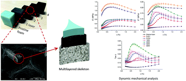
A region with high CNT content in the composite foam is required to make an efficient use of the nanotube–nanotube interfacial sliding mechanism. Nano-ink coatings applied to the cellular structure of an open cell foam can generate the type of microstructure able to provide enhancements to the damping performance. However, to the best of the authors' knowledge very few studies have been performed with a conductive nanoink coating on polymer open cell foams. These studies have focused mainly on pressure sensitive sensing applications with a single layer of ink coating the foam skeleton,17 or infiltrating the foam cell.18 No work has been published so far about the damping performance of nano-coated open cell foams making use of the nanotube–nanotube damping mechanism. Another aspect of novelty of this work is the development and use of multi-layer ink coating technique to generate highly entangled CNT network region on the foam skeleton by repeating a simple dip-coating process. The process creates cellular foams with individual strut having a multilayer micro-architecture where the MWNT ink layer represents a sandwich core and the polyurethane dispersion (PUD) coating acts as sealant layer. Foams containing 1 to 4 layers of MWNT coatings were analysed in view of their coating coverage, electrical conductivity and viscoelastic damping performance. The viscoelastic characterisation was performed following Dynamic Mechanical Analyser (DMA) techniques, while stiffness and energy absorption properties were determined by mechanical compressive quasi-static and cyclic tests.
![]() | ||
Fig. 1 TEM images of the MWNT–COOH (a) at ×50![]() ![]() |
In a second step the silane-treated foam was immersed into the MWNT ink. The infiltration of the ink into the foam cells was facilitated by agitating the foam samples. The foam was then removed from the ink, hand pressed and placed on an absorbent sheet to remove excessive material. After drying at 80 °C for 12 hours the nanoink-coated foam was removed from the oven for the top coating procedure.
We used a water-based aliphatic PUD U4101 with solids content of 39–41 and elongation at break of 1400% (ref. 21) provided by Alberdingk Boley and used as top coating. This solution was used to seal the MWNT coating as a sandwich core between the base PU foam strut and PUD, as illustrated in Fig. 2. The foam was then dried in the oven for 5 hours at 50 °C.
![]() | ||
Fig. 2 SEM image of pristine PU foam strut (a) and, schematic of the coating formed strut sandwich structure (showing one layer of MWNT coating here) (b). |
The surface coverage of foam strut by the MWNTs is a key factor that governs the damping performance. To make use of the CNT–CNT frictional slippage existing in multi-walled nanotubes the strut surface should preferably fully covered by the MWNTs ink coating. Therefore, we produced one layer of MWNT ink coating with various ink concentrations (0.01 wt%, 0.05 wt%, 0.1 wt%, 0.2 wt%, and 0.3 wt%) to evaluate the influence and type of surface coverage. The coating process described above can be considered as the procedure necessary to produce one sandwich-type layer coating. By repeating the same procedure 1 to 3 times and treating the PUD top coat as the next layer's base coat we could produce samples containing 1 to 4 layers of micro-architectured sandwich rib coating. Pristine and PUD coated foams without the MWNT ink ribs sandwich core were also fabricated and tested for control. Fig. 3 shows the as-produced foams (200 × 300 × 400 mm3) containing between zero and four layers of the sandwich coating.
The amplitude, frequency and temperature dependency of the viscoelastic properties (storage modulus E′, loss modulus E′′ and tanδ) of the multilayer-coated foams were evaluated by using a Dynamic Mechanical Analyser (DMA+/NUT/022/B-Metravib) under compression mode. The specimens were subjected to a sinusoidal dynamic strain varying from 0.2% to 2% at a fixed frequency of 10 Hz at room temperature. Frequency scans of 1–40 Hz were then applied under a temperature sweep between 30 °C and 130 °C with 1% strain under a heating rate of 5 °C min−1. Both static and quasi-static compression–compression cyclic tests were performed at room temperature by using Shimadzu AGS X Series universal testing machine with 1 kN load cell at crosshead speed of 5 mm min−1 under stroke control with maximum stroke of 1.5 mm (3.75% of compressive strain) in 1 Hz triangular waveform under room temperature and 36% humidity. The aim of these tests was to obtain an overall characterization on the static and cyclic performance of the various types of foams and provide a benchmark to the DMA data. An initial set of five cyclic loading at 1 Hz and room temperature was also performed to verify the mechanical stability of the sample. After the first cycles, the hysteresis curves and elastic modulus of the foams showed a robust stability. DSC measurements were performed on a TA Instruments Q100 Calorimeter in two scans. The first scan was to remove the thermal history of the samples, whereas the second scan was performed between −70 °C and 300 °C with a heating/cooling rate of 10 °C min−1. The identification of the transition temperature by the DSC measurements was performed following the ASTM D7426-08 standard. Five specimens from each sample batch were tested to acquire a statistical distribution of the results.
![]() | ||
Fig. 4 SEM images of PU foam skeleton coated with MWNT ink with concentration of 0.01 wt% (a1 and a2), 0.05 wt% (b1 and b2), 0.1 wt% (c1 and c2), 0.2 wt% (d1 and d2), and 0.3 wt% (e1 and e2). |
As the ink concentration increases a more pronounced deposition of MWNTs starts to appear on foam surface. The 0.1 wt% (Fig. 4(c2)), 0.2 wt% (Fig. 4(d2)) and 0.3 wt% (Fig. 4(e2)) ink-coated surfaces all reveal similar morphologies, with the MWNTs bridging each other and forming highly entangled MWNTs networks. The morphologies of the MWNTs network distributions appear to be very similar both at the surface and internal regions of the foam (see the SEM images of the ESI†). This feature indicates that any non-uniform dip-coating effect due to the permeability of the foam was negligible, because the low surface tension of the IPA, large cells dimensions (∼500 μm) and the small sample sizes made the infiltration process effective.
This surface morphology of the MWNT coating can be evinced by observing the foam electrical conductivity versus the actual weight percentage of the MWNT coated on the foam skeleton (Fig. 5). In agreement with observations from the SEM images, the percolation threshold region is between 0.05 wt% and 0.1 wt% of the ink concentration. At relatively high ink concentrations (0.1 wt% 0.2 wt% and 0.3 wt% ink) the coated foam with well-developed MWNT conductive networks showed a conductivity of 1 S m−1, ∼1200% times higher than the one provided by the 0.05 wt% ink coated foam samples. Chun et al.18 have applied graphene ink layers on PU foam and observed the presence of a foam conductivity of ∼0.56 S m−1 with 30 layers of coating. The foam presented in our work features the double of that conductivity value, with only one coating layer and half of the ink concentration used in ref. 18. Instead of filling the foam cell with nanoparticles, our ink coating method requires a coating on the foam strut only, and significantly lower quantity of CNTs (half of the ink concentration) by making use of the entanglement of CNT networks.
![]() | ||
Fig. 5 One layer ink coated foam electrical conductivity and coating weight fraction versus ink concentration. |
Due to the saturation of the surface coverage the electrical conductivity did not increase further by a significant amount, showing only a ∼50% improvement when tripling the MWNT content from 0.1 wt% to 0.3 wt%. This surface coverage saturation is also proved by the plateau region in Fig. 5. It can be therefore concluded that the 0.1 wt% MWNT ink was the most effective for the surface coverage of the foam skeleton, and was then adopted for the successive studies of the multilayer coating analysis.
![]() | ||
Fig. 6 Plot of single compression stress–strain curve (a), elastic modulus and stress at 10% strain (b), and specific modulus and specific stress at 10% strain (c) of multilayer coated foams. |
Fig. 7 shows the normalised energy dissipated in one loading–unloading cycle (ΔW) by foams in quasi-static tests and the corresponding loss factor (η) given by the following equation:
![]() | (1) |
![]() | ||
Fig. 7 Normalised dissipated energy and loss factor of multilayer coated foams obtained from quasi-static cyclic compression tests. |
In Fig. 7 the dissipated energy ΔW for each coated foam configuration has been normalised against the analogous quantity related to the pristine foams. As shown in Fig. 7 both the dissipated energy and the loss factor increased with increasing MWNT coating layers, when compared with the results from the baseline PU foam. The 4-layers MWNTs coated foams exhibited a ∼380% increment in ΔW, with loss factors close to ∼0.25. This value is 66% higher than the one of the pristine PU foam. Both the PUD layers and the MWNT core layers appeared to contribute to the observed improvements in the quasi-static and cyclic mechanical properties. By comparing the performance of the pristine foam and the ‘1PUD’ ‘4PUD’ and ‘4MW’ porous configurations it is however possible to conclude that the presence of a PUD layer has only a limited effect in enhancing the damping performance. One layer of PUD coating provided an increase of ∼80% of the energy dissipation compared with the baseline PU foam, but by adding 4 layers of PUD coating a further increment of only ∼45% was obtained. On the opposite, the 4-layers MWNT coated samples (4MW) added another ∼260% increment of ΔW on top of the one provided by the samples with four layers of PUD coating. It is apparent that this ∼260% increase in energy dissipation can be solely attributed to the presence of the MWNT core layer, and proves the fact that the MWNT core layer played a key role in the enhancement of the damping performance. It is also interesting to notice that the ‘1MW’ sample showed a smaller ΔW normalised value than that the one exhibited by the 1PUD configuration that contained the same number of PUD layers, and was expected to exhibit a lower normalised energy dissipated. This fact could be explained by the strong chemical bonding existing between the MWNT–COOH, PU and PUD layer, together with the two types of damping mechanisms within the core layer itself, which will be discussed in the following paragraph.
![]() | ||
Fig. 8 Storage modulus (a), loss modulus (b), and loss factor (c) as a function of the dynamic strain obtained from DMA analysis. |
Similarly, with the results from the quasi-static cyclic loading tests, the loss modulus, increased with increasing numbers of MWNT coating layers (Fig. 8(b)). As discussed previously, both the PUD layers and the MWNT core contributed to this increment. Additionally, two possible damping mechanisms within the MWNT core layers could be further argued for. In a similar way to any conventional CNTs embedded in polymer matrix nanocomposites two main damping mechanisms exist in the MWNT core: the energy dissipation caused by (a) CNT–polymer interfacial sliding and (b) the energy dissipation caused by the CNT–CNT sliding.12 Unlike conventional polymer based nanocomposites that are mainly characterised by the stick-slip mechanism at the CNT–polymer interface, the MWNT core contains more entangled CNTs that provide a larger CNT–CNT interface, and therefore would dissipate energy mainly through the CNT–CNT interfacial sliding. When considering the chemical bond formed by the –COOH functional group between the MWNTs and the PUDs, the CNT–polymer interface retains a much stronger bonding and therefore requires a higher critical shear strain (stress) to activate the CNT–polymer interfacial sliding mechanism compared to the case of the interfacial sliding between CNTs.12 Hence, as indicated in Fig. 8(b), the sharp increment in loss modulus at lower dynamic strain is caused primarily by the CNT–CNT interfacial sliding mechanism. With the increase of the dynamic strain the other CNT–polymer energy dissipation mechanism started to contribute to the overall damping performance, reaching a peak of storage and loss modulus at a specific strain, with the two damping mechanism been fully activated. The position of the E′′ peak shifted to lower dynamic strains with increasing numbers of MWNT layers as indicated by the arrow in Fig. 8(b), this phenomenon likely caused by varying interface shear stresses between each ink layer. The samples coated by four MWNT layers revealed a ∼660% increment in loss modulus compared with the one of the baseline PU foam.
The loss factor (tanδ) is plotted in Fig. 8(c). Although the samples containing between three and four layers of coating showed the higher loss modulus, their loss factor dropped in values close to the ones of the PUD coated sample due to their high storage modulus. The samples containing two layers of coating showed the highest loss factor (∼0.37 at 0.66% strain), increased by 270% and 85% compared to the ones of the baseline PU and 1PUD layer coated foams respectively. Such increment in loss factor by using the CNT–CNT frictional sliding is much more effective than the one present in foams that take advantage of the CNT–polymer matrix damping mechanism. For example, Bandarian9 and co-workers have used the foaming technique with 0.1 wt% COOH functionalised MWNTs embedded in the foam strut, and observed an increase of the loss factor by ∼20% from 0.21 to 0.25 at 20 °C. In our case, the ink-coated foam shows a 270% increment in loss factor for 1 wt% with 2 coating layers, which is however a higher weight fraction than the one used in ref. 9. Our in-coated foams appear to be also more effective in damping than high-energy dissipation auxetic foams (see Bianchi25) has observed that the damping capability of conventional open cell PU foams improves by transforming the same pristine foam used in this study into an auxetic phase, with the foam loss factor increased by 83% from 0.12 to 0.22. By applying the ink coating technique proposed in this work we have however achieved a further 100% increment in loss factor.
The viscoelastic properties of the ink coated foams were described in master curves (Fig. 9) superposed using the Williams–Landel–Ferry model26 with a reference temperature of 75 °C. The data used for time–temperature superposition was selected according to the Cole–Cole plot, which is a log–log plot of the loss modulus vs. storage modulus used to determine whether the tested material is thermodynamically simple.27 These plots are considered a standard in industry to evaluate the performance of the material outside the experimental limitations.28
The pristine foam (‘1MW’) and the ‘4MW’ samples showed a relatively smooth fitting, whereas the ‘2MW’ and ‘3MW’ samples had more scattered data points not aligned with the fitted curve, which indicates that the assumptions of the WLF are not strictly met. The ‘1MW’ samples containing one layer of coating exhibit a density that is almost the same as the one of the pristine foam. Those samples allowed most of the trapped air in the pores to escape during the test, whereas the ‘2MW’ and ‘3MW’ foams contained an increased skeleton thickness retaining more air trapped inside in the foam during the cyclic compression. For this reason the sample cannot be considered as behaving as an equivalent thermodynamically simple material. With the number of coating layers further increased to four the nomogram of the ‘4MW’ foam shows however a smooth fitting due to the stiffening effect on the foam struts, which makes the foam to exhibit a viscoelastic performance similar to the one of a dense material. The greater uncertainties at the extreme upper and lower temperatures may have caused the mismatch28 at the lower and higher frequencies of the nomogram.
The peak loss factor and the corresponding optimal reduced frequency for each specimen are indicated in the plots. The optimal reduced frequency increased with increasing numbers of the MWNT coating layers, dropping back to 1.6 × 10⁻⁴ with four layers of coating. In agreement with what observed on the strain scan (Fig. 8), the 2MW samples showed the highest values of loss factor, and the introduction of more coating layers resulted in a drop of the loss factors due to the increased storage modulus.
Footnote |
† Electronic supplementary information (ESI) available. See DOI: 10.1039/c6ra15868d |
This journal is © The Royal Society of Chemistry 2016 |