DOI:
10.1039/C6RA15821H
(Paper)
RSC Adv., 2016,
6, 62876-62883
A novel approach to fabricate stable graphene layers on electrode surfaces using simultaneous electroreduction of diazonium cations and graphene oxide†
Received
27th January 2016
, Accepted 27th June 2016
First published on 27th June 2016
Abstract
The short time fabrication of graphene layers on glassy carbon (GCE) and indium tin oxide (ITO) electrodes by simultaneous electroreduction of graphene oxide (GO) and diazonium salts was described for the first time. Initially, aminotriazine groups were introduced on the electrode surface by an in situ process of a diazotization protocol using melamine. Subsequent electrochemical reduction of diazonium groups immersed in GO solution leads to the formation of graphene layers on the electrode surface. Using this methodology, stable graphene layers were fabricated within 10 min on the electrode surface. The simultaneous reduction of triazine diazonium cations and GO and the formation of graphene layers on the electrode surface were confirmed by X-ray photoelectron spectroscopy (XPS), Raman spectroscopy, X-ray diffraction (XRD), scanning electron microscopy (SEM) and cyclic voltammetry (CV). The absence of characteristic peaks in XPS for the diazonium group (403.7 and 405.6 eV) and oxygen functionalities confirmed the reduction of the triazine diazonium cations and GO on the electrode surface. Raman spectra reveal that the intensity ratio of D and G bands (1340 and 1584 cm−1) was increased after the electrochemical reduction of GO. The SEM image shows the formation of thin layers of graphene. Impedance studies indicate that the electron transfer reaction of [Fe(CN)6]3−/4− was higher at the graphene modified electrode (4.10 × 10⁻⁴ cm s−1) than at bare (3.77 × 10⁻⁵ cm s−1) GC electrode. The electrocatalytic activity of the graphene modified electrode was examined by studying the oxidation of dopamine (DA). The graphene modified electrode not only increased the oxidation current of DA enormously but also shifted its potential towards a less positive potential when compared to bare and GO modified GC electrodes. The present strategy of modification of graphene is simple and requires a very short time.
Introduction
Graphene is a class of two-dimensional carbon materials, which are densely packed in a honeycomb crystal lattice, and it has received remarkable attention in recent years.1 The unique physical and chemical properties of graphene including high surface area,2 excellent conductivity,2 mechanical strength,3 tunable optical properties,4 high electron mobility5 and a fast heterogeneous electron transfer rate6 makes it a potential candidate for a variety of applications including in electronic devices,7 nanocomposite materials,8 supercapacitors,9 fuel cells,10 sensors,11 drug delivery and cell imaging.12 Generally, graphene is produced by mechanical exfoliation,13 epitaxial growth14 and chemical reduction of GO suspension.15 Among these methods, chemical reduction method is the best one because it is reliable, scalable and low cost.15 In general, GO is synthesized by the modified Hummer's method.16 During the oxidation, the π–π electronic conjugation of graphite is destroyed and the carbon sheets are modified with the epoxide and hydroxyl groups in their basal planes and the carbonyl and carboxyl groups at their edges.17,18 To retain the aromatic honeycomb structure, the GO is reduced by hydrazine hydrate,19 NaBH4,20 hydroquinone21 and hydroxylamine.22 However, these reducing agents employed in the reduction could contaminate the resulting graphene materials.
Electrochemical reduction of GO has gained much interest in recent years because it is a green approach besides a thin film of graphene layer can be prepared on conducting substrates by this method.23–25 Formation of graphene films on conducting substrates was usually achieved by direct electrochemical deposition of GO, drop casting of graphene, drop-casting of GO followed by its electrochemical reduction, spray-coating, spin-coating and layer-by-layer assembly.26–31 However, the stability, long time storage, thickness and uniformity of graphene films cannot be achieved by these methods. It has been already demonstrated that aryl diazonium salt chemistry can produce significantly more stable organic layers on electrode surface than self-assembled monolayers due to the carbide bond formation.32 Thus, the aim of the present study is to fabricate graphene films on electrode surface by two diazotization protocol based on the reduction of melamine, GO and triazine diazonium cations simultaneously in a single step. The characterization of the resulting graphene modified electrode surfaces was performed by XPS, Raman spectroscopy, XRD, SEM and CV. Finally, the electrocatalytic activity of the graphene modified electrode was examined by studying the oxidation of DA.
Experimental
Chemicals
Graphite powder was purchased from Alfa Aesar. Dopamine (DA) was purchased from Sigma-Aldrich and was used as received. Potassium permanganate (KMnO4), sodium nitrate (NaNO3), sulfuric acid (H2SO4), hydrogen peroxide (H2O2), melamine, sodium nitrite (NaNO2) and hydrochloric acid (HCl) were purchased from Merck (India). Indium tin oxide (ITO) substrates were purchased from Asahi Beer Optical Ltd, Japan. 0.2 M phosphate buffer (PB) solution (pH 7.2) was prepared by using Na2HPO4 and NaH2PO4. All other chemicals were of analytical reagent grade and were used as received. Double distilled water was used to prepare the solutions.
Instrumentation
XPS measurements were carried out by using Shimadzu Axis 165 high performance multi-technique analysis using an Al Kα source with pass energy of 80 eV, where the pressure in the analysis chamber was lower than 1 × 10⁻⁸ Torr and the dwell time was 458 ms. The binding energies for identical samples were reproducible within ±0.10 eV. A survey spectrum and core-level spectra of C 1s (280–290 eV), O 1s (526–538 eV), and N 1s (396–410 eV) regions were systematically recorded. The energy scale of the instrument was calibrated by setting Au 4f7/2 = 84.00 eV and Ag 3d5/2 = 368.70 eV. The spectra were calibrated on the C 1s peak (285.0 eV). Atomic sensitivity factors are C 1s 1.0, O 1s 2.93, S 2p 1.68, N 1s 1.8, and Au 4f7/2 9.58. Spectra were analyzed using XPSPEAK41 software. After subtraction of a Shirley background, all spectra were fit by use of a convolution of Gaussian functions. The peak-fitting procedure used a minimum number of peaks consistent with the best fit with consideration of peak position, full width at half-maximum, and intensity. Raman spectra were recorded on a Horiba JY LabRAM HR800 Raman spectrometer coupled with microscope in reflectance mode with 633 nm excitation laser source and a spectral resolution of 0.3 cm−1. X-ray diffraction analysis was carried out with a Rigaku X-ray diffraction unit using Ni-filtered Cu Kα (λ = 1.5406 Å) radiation. SEM measurements were carried out by using VEGA3 TESCAN. Electrochemical measurements were performed in a conventional two compartment three electrode cell with a mirror polished 3 mm GCE as a working electrode, Pt wire as a counter electrode and a KCl saturated Ag/AgCl as a reference electrode. All the electrochemical measurements were carried out with CHI model 634B (Austin, TX, USA) Electrochemical Workstation. All the electrochemical measurements were carried out under nitrogen atmosphere at room temperature.
Synthesis of GO
GO was synthesized using the Hummer's method with a slight modification.17 Concentrated H2SO4 (12 mL) was added to flake graphite (0.5 g) and NaNO3 (0.25 g) and the mixture was cooled to 0 °C. Then, KMnO4 was added slowly into the mixture and the temperature was maintained at 20 °C. The reaction mixture was warmed to 35 °C and stirred for 30 min. To this mixture, 23 mL of water was added, which produce an exotherm to 98 °C and the temperature was maintained for 15 min by external heating. The reaction was then terminated by the large addition of water (72 mL) and 0.5 mL of 30% H2O2. Finally, the reaction mixture was cooled, washed with 0.1 M HCl and water to remove the metal ions and then dried.
Fabrication of graphene modified GCE
The fabrication of graphene modified electrode is schematically shown in Scheme 1. The selective diazotization of one amine group of melamine has been already reported.33,34 To a mixture of 2 mM melamine and 0.5 M HCl, 2 mM cold sodium nitrite was added drop wise to generate the diazonium cations in situ in the electrochemical cell. 2,4-Diamino-1,3,5-triazine (AT) moieties were introduced on the GCE by in situ generation based on the diazotization of melamine. The mixture was degassed with nitrogen flow. The electrochemical modification was immediately performed on the cleaned GCE. The electrode was rinsed with double distilled water after surface modification with the aminotriazine group and sonicated for 2 minutes in acetonitrile and then rinsed with double distilled water. GO colloidal suspension was prepared by adding 1 mg mL−1 GO solution to 0.2 M pH 7 phosphate buffer solution (PBS) via homogenous mixing. The GO suspension in the electrochemical cell was deoxygenated using nitrogen gas. Simultaneous electrochemical reduction of diazonium cations and GO on GCE was performed via AT grafted GCE by immersing in a mixture of 0.5 M HCl and 5 mM NaNO2 for 2 min followed by cycling between +0.6 V and −1.4 V vs. Ag/AgCl in GO solution at a scan rate of 50 mV s−1. GO modified electrode was prepared by the reduction of diazonium cations and GO in the potential window from +0.60 to −0.70 V. For Raman and XPS, graphene modified ITO plates prepared by the same procedure were used. Since electrografting is mainly based on radical mechanism the mode of attachment of aryl groups on GC and ITO electrodes remains same.
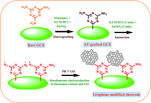 |
| | Scheme 1 Schematic representation of the modification of graphene on GCE. | |
Results and discussion
Fabrication of graphene on grafted electrode surfaces
The methodology for the preparation of graphene on electrode surface is illustrated in Scheme 1. Graphene modified surface can be obtained by the following two diazotization-step protocol. The first step is to generate in situ aminotriazine radicals from melamine to modify the electrode surface with aminotriazine groups. Fig. S1† shows the CV obtained for the electrografting of aminotriazine diazonium cations generated in situ from melamine on GCE surface. When the potential is scanned from 0.6 to −0.8 V, a reduction wave was observed at −0.47 V corresponding to the reduction of aminotriazine diazonium cations to form an aminotriazine radicals and subsequently they attached on GCE. Similar result has been already reported for the electrochemical reduction of several diazonium salts on various substrates.35–37 The next step is the conversion of terminal amino groups of triazine moieties into a diazonium cations using the in situ method.37,38 Finally, the graphene film is formed via the simultaneous reduction of triazine diazonium cations and GO on GCE. Fig. 1 shows the CV obtained for the simultaneous reduction of diazonium cations and GO on GCE. When triazine diazonium cations grafted GCE is scanned from 0.6 to −1.4 V, a typical reduction wave is observed at −0.55 V, corresponding to the reduction of triazine diazonium cations to form triazine radicals (curve a)35–37 and subsequently the formed radicals attached with the GO. Further, the reduction wave appeared at −1.0 V is due to the reduction of oxygen functional groups present on the surface of GO.24 In order to confirm the reduction of oxygen functional groups, the electroreduction of triazine diazonium cations in the absence of GO solution was carried out. The diazonium cations reduction peak was observed at −0.60 V (curve b) whereas the GO reduction peak was absent. This confirms the simultaneous reduction of diazonium cations and GO. Interestingly, the reduction current of GO is very less when compared to the previously reported electrochemically reduced GO on electrode surfaces.24,25 This is mainly due to the attachment of less content of GO, which leads to the formation of thin layers of graphene after electrochemical reduction.
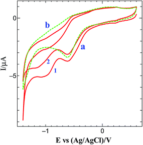 |
| | Fig. 1 (a) Simultaneous electrochemical reduction of diazonium cations and GO and (b) absence of GO on diazonium cations grafted on GCE in 0.2 M PB (pH 7) solution at a scan rate of 50 mV s−1. Cycle numbers are indicated in the curves. | |
Impedance spectral studies
Impedance measurements were performed to investigate the conductivity of graphene modified GCE in 1 mM K3[Fe(CN)6] containing 0.2 M PB solution (pH 7) at scanning frequencies from 0.01 to 100![[thin space (1/6-em)]](https://www.rsc.org/images/entities/char_2009.gif) 000 Hz (Fig. 2). The obtained complex plane plots (Nyquist plot) for imaginary component of impedance against real component of impedance (−Z′′ vs. Z′) were best fit with Randles equivalent circuit model [RS(CPE − RCT)] (Fig. 2, inset) for the bare GC and graphene modified electrodes using Zview software. In this model, solution resistance (RS) and constant phase element (CPE) were linked in series circuit and charge-transfer resistance (RCT) was linked with CPE in parallel circuit. The charge-transfer resistance (RCT), the semicircle diameter at the higher frequencies in the Nyquist plot of impedance spectroscopy, controls the interfacial electron-transfer rate of the redox probe between the solution and the electrode.35 As a result, RCT can be used to illustrate the interface properties of the electrode. The graphene modified electrode shows less RCT value (curve b) compared to bare GCE (curves a). The RCT values for the bare GC and graphene modified electrodes were found to be 100.8 and 9.2 kΩ, respectively. The obtained RS, CPE, and RCT values were listed in Table S1 (ESI†). After simultaneous reduction of diazonium cations and GO on GCE, the RCT value was decreased compared to that of bare GCE mainly due to the regeneration of aromatic lattice of graphene layers by the removal of oxygen functional groups which increases the electrical conductivity. The heterogeneous electron-transfer rate constant (ket) for the redox process of [Fe(CN)6]3−/4− probe at the modified electrodes can be calculated using the following equation.39
000 Hz (Fig. 2). The obtained complex plane plots (Nyquist plot) for imaginary component of impedance against real component of impedance (−Z′′ vs. Z′) were best fit with Randles equivalent circuit model [RS(CPE − RCT)] (Fig. 2, inset) for the bare GC and graphene modified electrodes using Zview software. In this model, solution resistance (RS) and constant phase element (CPE) were linked in series circuit and charge-transfer resistance (RCT) was linked with CPE in parallel circuit. The charge-transfer resistance (RCT), the semicircle diameter at the higher frequencies in the Nyquist plot of impedance spectroscopy, controls the interfacial electron-transfer rate of the redox probe between the solution and the electrode.35 As a result, RCT can be used to illustrate the interface properties of the electrode. The graphene modified electrode shows less RCT value (curve b) compared to bare GCE (curves a). The RCT values for the bare GC and graphene modified electrodes were found to be 100.8 and 9.2 kΩ, respectively. The obtained RS, CPE, and RCT values were listed in Table S1 (ESI†). After simultaneous reduction of diazonium cations and GO on GCE, the RCT value was decreased compared to that of bare GCE mainly due to the regeneration of aromatic lattice of graphene layers by the removal of oxygen functional groups which increases the electrical conductivity. The heterogeneous electron-transfer rate constant (ket) for the redox process of [Fe(CN)6]3−/4− probe at the modified electrodes can be calculated using the following equation.39
where R is the gas constant, T is the temperature (K), F is the Faraday constant, A is the electrode area (cm2), C0 is the concentration of the redox couple in the bulk solution and n is the number of transferred electrons per molecule of the redox probe (n = 1 for the K3[Fe(CN)6] probe). The calculated ket values are 3.77 × 10⁻⁵ and 4.10 × 10⁻⁴ cm s−1 for bare and graphene modified electrodes, respectively. The obtained higher ket value for the graphene modified electrode indicates that the electron transfer reaction was faster at this electrode when compared to bare GCE.
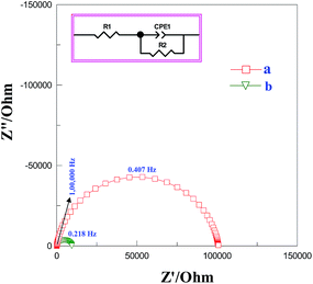 |
| | Fig. 2 Nyquist plot for (a) bare and (b) graphene modified GCEs in 1 mM K3[Fe(CN)6] containing 0.2 M PB solution (pH 7) at scanning frequencies from 0.01 to 100000 Hz. Inset: equivalent electrical circuit used for fitting the impedance spectra. | |
Characterization by XPS
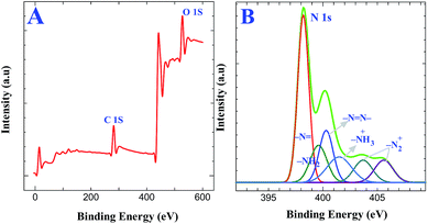
XPS experiments were carried out to confirm the covalent attachment of GO on triazine diazonium cations followed by its reduction. XPS obtained for AT grafted ITO are shown in Fig. S2A.† The analysis of N 1s core level spectra demonstrates the presence of aminotriazine group using Gaussian functions after background correction (Fig. S2B†). The N 1s core level spectra for the AT grafted ITO show three components at 398.2, 399.6 and 400.2 eV, which were assigned to the sp2 hybridized nitrogen atoms linked to two carbon atoms in the triazine ring, amine functionalities on the triazine ring and azo bonds, respectively.34,40 The peak-fitting results and their assignments are given in Table 1. Further, we have characterized the formation of diazonium cations on AT grafted surface and the simultaneous reduction of both diazonium cations and GO to form graphene layers on the electrode surface. Fig. 3A displays the XPS obtained for triazine diazonium grafted ITO. The N 1s spectrum (Fig. 3B) can be fitted with six components located at 398.2, 399.6, 400.2, 401.5, 403.7 and 405.6 eV.34,40 The intensity due to amino group (399.6 eV) is drastically decreased because it is converted to diazonium cation. This can also be confirmed from the characteristics of diazonium groups located at 403.7 and 405.6 eV (ref. 40) (Fig. 3B). These results reveal that the amino groups were converted to diazonium functionalities during the chemical treatment in the presence of 0.5 M HCl and 5 mM NaNO2 for 2 min. The other component at 401.5 eV indicates the presence of protonated amine group. The obtained XPS results provide a strong evidence for the formation of diazonium cations on the electrode surface.
Table 1 Peak assignments for XPS
| Sample |
N 1s XPS: peak position (eV) and assignments |
| AT grafted ITO |
398.2 ∼ triazine ring |
| 399.4 ∼ NH2 |
400.2 ∼ N![[double bond, length as m-dash]](https://www.rsc.org/images/entities/char_e001.gif) N– N– |
| Triazine diazonium cations modified ITO |
398.2 ∼ triazine ring |
| 399.4 ∼ NH2 |
| 400.2 ∼ NN– |
| 401.5 ∼ NH3+ |
| 403.7, 405.6 ∼ N2+ (diazonium peak) |
| GO modified ITO |
398.2 ∼ triazine ring |
| 399.4 ∼ NH2 |
| 400.2 ∼ NN– |
| Graphene modified ITO |
398.2 ∼ triazine ring |
| 399.4 ∼ NH2 |
| 400.2 ∼ NN– |
 |
| | Fig. 3 XPS of triazine diazonium cations grafted ITO substrate: (A) survey spectrum and (B) enlarged spectra for N 1s region. | |
Further, XPS measurements provided direct evidence for the attachment of GO and its electrochemical reduction. Simultaneous electrochemical reduction of GO and triazine diazonium cations on GC electrode was performed by cycling between +0.6 V and −1.4 V at a scan rate of 50 mV s−1 in GO solution containing triazine diazonium cations. This step provides efficient way to form graphene films on electrode surface. Fig. 4A shows the XPS survey spectra of GO and graphene modified ITO substrates prepared by the simultaneous reduction of triazine diazonium cations and GO. The peak at 284.4 eV corresponds to the C 1s peak of sp2 carbon and the peak at 531 eV corresponds to the O 1s spectrum of different oxygen functional groups. The sp2 carbon peak intensity is much higher than the AT grafted ITO (Fig. S2A†) and triazine diazonium cations grafted ITO (Fig. 3A). The calculated C/O peak intensity values for GO modified ITO and graphene modified ITO substrates are 0.58 and 3.78, respectively (Table S2†). The calculated C/O peak intensity value for graphene modified ITO is 3.78, which is lower than the reported value for the reduction of GO by green reducing agents such as baker's yeast (C/O of 5.90)41 and caffeic acid (C/O of 7.15).42 On the other hand, this value is very significant because the formation of graphene film was achieved within 10 min. The attachment of GO on triazine diazonium cations and its electrochemical reduction were also confirmed by fitting C 1s spectra of GO modified ITO (Fig. 4B) graphene modified ITO (Fig. 4C). XPS of GO display the four peaks at 284.6, 286.5, 287.6 and 289.1 eV, corresponding to the C–C in the aromatic rings, hydroxyl, epoxy and carbonyl groups, respectively. It confirms the successful attachment of GO on triazine ring. The C 1s spectrum of graphene modified ITO shows two peaks centering at 284.6 eV (–CC–) and 286.5 eV (C–OH). The peak intensity of (C–OH) is very less when compared to –CC– bond. Further, the absence of peaks at 287.6 eV (CO) and 289.1 eV (OC–OH)40 reveals that a large number of oxygen-containing groups were removed and the majority of the sp2 carbon networks were restored. The absence of diazonium group peak at 403.7 and 405.6 eV in N 1s spectrum (Fig. S3A and B†) strongly confirms the simultaneous reduction process and the conversion of diazonium moieties to radicals with the loss of N2. The attachment of the GO is assumed to occur via stable C–C bonds. The peak assignments are summarized in Table 1.
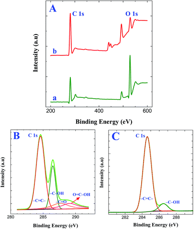 |
| | Fig. 4 (A) XPS survey spectra obtained for (a) GO modified ITO and (b) graphene modified ITO substrates. XPS of C 1s spectra obtained for (B) GO modified ITO and (C) graphene modified ITO substrates. | |
Characterization by Raman spectroscopy
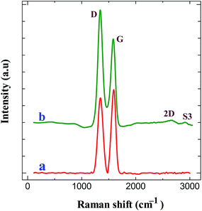
Raman spectroscopy is an important tool to characterize the carbon materials. Fig. 5 displays the Raman spectra of GO modified ITO and graphene modified ITO substrates. Both spectra show the presence of the D and G bands related to the first-order scattering of the E2g phonon from sp2 carbon (graphite lattice), and the band resulting from the structural imperfections (disorder band) created by the hydroxyl and epoxide groups on the carbon basal plane, respectively.42 The GO modified ITO shows two peaks at 1345 and 1592 cm−1, corresponding to D and G peaks of GO (curve a). After the electrochemical reduction, the graphene modified ITO shows the D and G peaks at 1340 and 1584 cm−1, respectively24,25,42 (curve b). Further, the reduction process shows an increase in the intensity of D band compared to that of G band and shift in the G band confirms the increasing defects in carbon basal plane and regeneration of aromatic backbone of graphene.25,42 The ratio of the intensities of the D and G bands of carbon products gives the useful information such as extent of chemical modification and defects which arise from vacancies and edges.30,42 The calculated ID/IG values for GO and graphene modified ITO substrates are 0.89 and 1.35, respectively. The increase of ID/IG ratio after reduction is generally observed in GO chemical reduction process. This can be explained by decrease in the average size of the sp2 domains upon reduction of the GO, where in new graphitic domains were formed that have smaller sizes than the GO. On the other hand, the increased fraction of graphene edges, which could also contribute to the increase in the ID/IG ratio. The existence of 2D (2667 cm−1) and S3 (2919 cm−1) bands30,43 at the graphene modified ITO substrate indicates the better graphitization achieved by the simultaneous electrochemical reduction when compared to GO modified ITO substrate. These results suggested the successful attachment of GO on ITO plate during the simultaneous reduction of diazonium cations and its electrochemical reduction retained the sp2 aromatic backbone of graphene. The peak assignments and the ID/IG values are summarized in Table 2. Using the ID/IG values, the average crystalline size of the carbon material was calculated by using the following equation.43
where, La is the average crystalline size and λ is the laser wavelength in nm. The calculated average crystalline sizes of GO modified ITO and graphene modified ITO substrates are 23.73 and 15.65 nm, respectively. The decrease in the average crystalline size of the graphene modified ITO can be explained by the creation of numerous new graphitic domains that are smaller in size than the ones presented in GO modified ITO.
 |
| | Fig. 5 Raman spectra obtained for (a) GO modified ITO and (b) graphene modified ITO substrates. | |
Table 2 Peak assignments for Raman spectra
| Sample |
Raman spectral data (cm−1) |
| D band |
G band |
2D band |
S3 band |
ID/IG |
| GO modified ITO |
1345 |
1592 |
— |
— |
0.89 |
| Graphene modified ITO |
1340 |
1584 |
2667 |
2919 |
1.35 |
Characterization by XRD and SEM
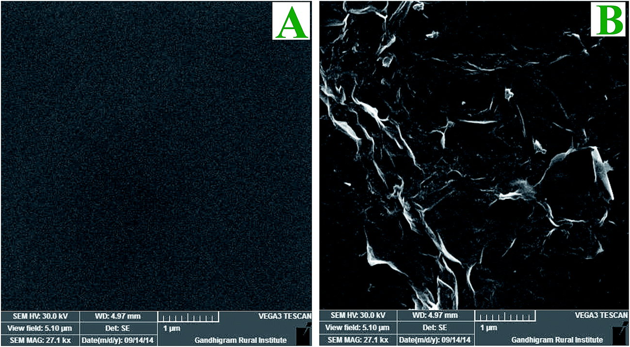
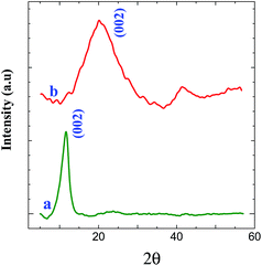
XRD measurements were carried out to investigate the phase and structure of the GO before and after its electrochemical reduction. Fig. 6 shows the XRD patterns of GO and graphene powder. The GO shows a characteristic peak of GO at 11.6° (002) (curve a), confirming the attachment of GO on triazine modified electrode.44 GO shows a peak at 2θ = 11.6° with an interlayer distance of 0.76 nm, which is greater than the interlayer distance of graphite (0.34 nm). After the electrochemical reduction of covalently attached GO, the peak at 11.6° (002) was completely vanished. This is due to the regeneration of crystalline nature of graphene by the removal of oxygen functional groups during electrochemical reduction which is confirmed from the appearance of peak at 23.6° (002) with a d-spacing of 0.37 nm (curve b).44 It is inferred from the XRD pattern that the GO was covalently attached on triazine ring and its electrochemical reduction retained graphite lattice on the surface of the electrode. The morphology of graphene modified GC plate was characterized by SEM. Fig. 7 shows the SEM images obtained for bare and graphene modified GC plates. In contrast to bare GC surface (Fig. 7A), the graphene modified plate shows thin layers of wrinkled and scrolled structure (Fig. 7B).24,25,45
 |
| | Fig. 6 XRD pattern obtained for (a) GO and (b) graphene (reduced GO) powder. | |
 |
| | Fig. 7 SEM images obtained for (A) bare and (B) graphene modified GC plates. | |
Electrocatalytic activity of graphene modified electrode towards DA
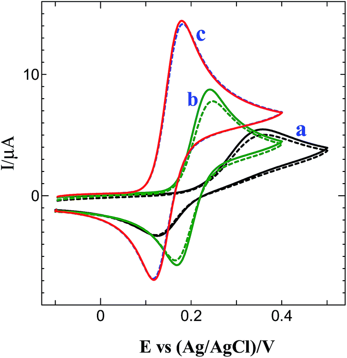
It is well known that cyclic voltammetry of the reversible redox probe is a valuable and convenient tool to test the kinetics barrier of the interface.46–52 Fig. S4† shows the CVs obtained for the inner-sphere probe, [Fe(CN)6]3−/[Fe(CN)6]4− in 0.1 M KCl at bare GCE and graphene modified electrode. It can be seen from Fig. S4† that redox peak current of graphene modified electrode is higher than the bare GCE. The peak separations of 89 and 100 mV were observed for the graphene modified electrode and bare GCE, respectively. The observed peak separation values suggested that the electron transfer rate at the graphene modified electrode is higher than the bare GCE. The electrocatalytic activity of the graphene modified electrode prepared by the present strategy was examined by studying the oxidation of DA.
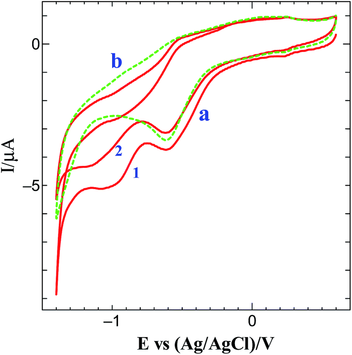
Fig. 8 shows the CVs obtained for 0.5 mM DA at bare, GO and graphene modified GCEs in 0.2 M PB solution (pH 7.2). The bare GCE shows an oxidation peak for DA at 0.35 V (curve a: solid line). After 5 cycles, the peak current was decreased at bare GCE (curve a: dotted line). The GO modified GCE shows an oxidation peak at 0.24 V for DA (curve b: solid line) and the peak current was decreased after 5 cycles (curve b: dotted line). On the other hand, a well-defined oxidation peak for DA was obtained at 0.18 V with much enhanced current at graphene modified GCE (curve c: solid line) with 1.7, 2.6-fold higher current and 60, 170 mV less positive potential shift than GO modified and bare GCEs. At this electrode, the oxidation peak was stable even after 5 cycles (curve c: dotted line). The obtained higher current with less positive potential shift for DA oxidation is attributed to the strong π–π interaction of DA with graphene.
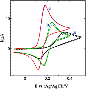 |
| | Fig. 8 CVs obtained for 0.5 mM DA at (a) bare, (b) GO modified and (c) graphene modified GC electrodes in 0.2 M PB solution (pH 7.2) (solid line: 1st cycle; dotted line: 5th cycle). | |
Conclusions
In the present study, we have demonstrated a simple strategy to fabricate stable graphene layers on electrode surface via the simultaneous electroreduction of diazonium cations and GO. The electrografting of GO on triazine diazonium cations and its electrochemical reduction leads to the formation of thin layers of graphene on electrode surface. The graphene modified electrode was characterized by CV, Raman spectroscopy, XRD, XPS and SEM. The crystalline nature of the graphene was confirmed by XRD. The absence of characteristic peaks for diazonium and oxygen functional group in the XPS confirmed the simultaneous reduction of the diazonium cations and GO. Raman spectrum shows the increase in the intensity ratio of D and G bands after the electrochemical reduction of GO layer, indicating that the graphene backbone was retained during the reduction process. SEM image shows the formation of thin layers of graphene on the electrode surface. Impedance studies reveal that the electron transfer reaction of [Fe(CN)6]3−/4− was higher at the graphene modified electrode than at bare GCE. Further, the graphene modified electrode showed greater electrocatalytic activity towards the oxidation of DA than bare and GO modified GCEs. The present strategy provides a robust method to modify electrodes with thin layers of graphene in short duration of time.
Acknowledgements
S. Kesavan thanks the Council of Scientific and Industrial Research (CSIR), New Delhi, India for the award of Senior Research Fellowship (09/715(0016)/2011-EMR-I). Financial support from the Department of Biotechnology (BT/PR10372/20/904/2013) is gratefully acknowledged.
References
- C. N. R. Rao, A. K. Sood, R. Voggu and K. S. Subramanyam, J. Phys. Chem. Lett., 2010, 1, 572 CrossRef CAS.
- K. Geim and K. S. Novoselov, Nat. Mater., 2007, 6, 183 CrossRef PubMed.
- C. Lee, X. D. Wei, J. W. Kysar and J. Hone, Science, 2008, 321, 385 CrossRef CAS PubMed.
- Y. Shi, W. Fang, K. Zhang, W. Zhang and L. Li, Small, 2009, 5, 2005 CrossRef CAS PubMed.
- K. I. Bolotin, K. J. Sikes, Z. Jiang, M. Klima, G. Fudenberg, J. Hone, P. Kim and H. L. Stormer, Solid State Commun., 2008, 146, 351 CrossRef CAS.
- K. Kampouris and C. E. Banks, Chem. Commun., 2010, 46, 8986 RSC.
- J. Hass, W. A. de Heer and E. H. Conrad, J. Phys.: Condens. Matter, 2008, 20, 323202 CrossRef.
- T. Ramanathan, A. A. Abdala, S. Stankovich, D. A. Dikin, M. Herrera-Alonso, R. D. Piner, D. H. Adamson, H. C. Schniepp, X. Chen, R. S. Ruoff, S. T. Nguyen, I. A. Aksay, R. K. Prud'homme and L. C. Brinson, Nat. Nanotechnol., 2008, 3, 327 CrossRef CAS PubMed.
- M. D. Stoller, S. Park, Y. Zhu, J. An and R. S. Rouff, Nano Lett., 2008, 8, 3498 CrossRef CAS PubMed.
- X. Wang, L. Zhi and K. Mullen, Nano Lett., 2008, 8, 323 CrossRef CAS PubMed.
- Y. Shao, J. Wang, H. Wu, J. Liu, I. A. Aksay and Y. Lin, Electroanalysis, 2010, 22, 1027 CrossRef CAS.
- X. M. Sun, Z. Liu, K. Welsher, J. T. Robinson, A. Goodwin, S. Zaric and H. J. Dai, Nano Res., 2008, 1, 203 CrossRef CAS PubMed.
- K. S. Novoselov, A. K. Geim, S. V. Morozov, D. Jiang, Y. Zhang, S. V. Dubonos, V. Grigorieva and A. A. Firsov, Science, 2004, 306, 666 CrossRef CAS PubMed.
- C. Berger, Z. M. Song, X. B. Li, X. S. Wu, N. Brown, C. Naud, D. Mayou, T. B. Li, J. Hass, A. N. Marchenkov, E. H. Conrad, P. N. First and W. A. de Heer, Science, 2006, 312, 1191 CrossRef CAS PubMed.
- S. Stankovich, D. A. Dikin, G. H. B. Dommett, K. M. Kohlhaas, E. J. Zimney, E. A. Stach, R. D. Piner, S. T. Nguyen and R. S. Ruoff, Nature, 2006, 442, 282 CrossRef CAS PubMed.
- W. S. Hummers and R. E. Offeman, J. Am. Chem. Soc., 1958, 80, 1339 CrossRef CAS.
- N. I. Kovtyukhova, P. J. Ollivier, B. R. Martin, T. E. Mallouk, S. A. Chizhik, E. V. Buzaneva and A. D. Gorchinskiy, Chem. Mater., 1999, 11, 771 CrossRef CAS.
- T. Szabo, O. Berkesi and I. Dekany, Carbon, 2005, 43, 3186 CrossRef CAS.
- S. Stankovich, D. A. Dikin, R. D. Piner, K. A. Kleinhammes, Y. Jia, Y. Wu, S. B. T. Nguyen and R. S. Ruoff, Carbon, 2007, 45, 1558 CrossRef CAS.
- J. R. Lomeda, C. D. Doyle, D. V. Kosynkin, W.-F. Hwang and J. M. Tour, J. Am. Chem. Soc., 2008, 130, 16201 CrossRef CAS PubMed.
- G. Wang, J. Yang, J. Park, X. Gou, B. Wang and H. Liu, J. Phys. Chem. C, 2008, 112, 8192 CrossRef CAS.
- X. Zhou, J. Zhang, H. Wu, H. Yang, J. Zhang and S. Guo, J. Phys. Chem. C, 2011, 115, 1957 Search PubMed.
- A. Ambrosi, C. K. Chua, A. Bonanni and M. Pumera, Chem. Rev., 2014, 114, 7150 CrossRef CAS PubMed.
- M. A. Raj and S. A. John, J. Phys. Chem. C, 2013, 117, 4326 CrossRef CAS.
- H. Guo, X. Wang, Q. Qian, F. Wang and X. Xia, ACS Nano, 2009, 3, 2653 CrossRef CAS PubMed.
- M. Du, T. Yang and K. J. Jiao, Mater. Chem., 2010, 20, 9253 RSC.
- L. Chen, Y. Tang, K. Wang, C. Liu and S. Luo, Electrochem. Commun., 2011, 13, 133 CrossRef CAS.
- Z. Wang, M. Shoji and H. Ogata, Analyst, 2011, 136, 4903 RSC.
- S. Gilje, S. Han, M. Wang, K. L. Wang and R. B. Kaner, Nano Lett., 2007, 7, 3394 CrossRef CAS PubMed.
- V. C. Tung, M. J. Allen, Y. Yang and R. B. Kaner, Nat. Nanotechnol., 2008, 4, 25 CrossRef PubMed.
- L. J. Cote, F. Kim and J. Huang, J. Am. Chem. Soc., 2009, 131, 1043 CrossRef CAS PubMed.
- D. Bélanger and J. Pinson, Chem. Soc. Rev., 2011, 40, 3995 RSC.
- A. A. Matnishyan, V. B. Zhukhovitskii and R. Z. Aleksanyan, USSR patent, SU565033, 1977.
- A. Grondein and D. Bélanger, Carbon, 2012, 50, 4335 CrossRef CAS.
- S. Kesavan, S. B. Revin and S. A. John, J. Mater. Chem., 2012, 22, 17560 RSC.
- J. Lyskawa and D. Bélanger, Chem. Mater., 2006, 18, 4755 CrossRef CAS.
- G. Liu, E. Luais and J. J. Gooding, Langmuir, 2011, 27, 4176 CrossRef CAS PubMed.
- P. Viel, X. T. Le, V. Huc, J. Bar, A. Benedetto, A. Le Goff, A. Filoramo, D. Alamarguy, S. Noel, L. Baraton and S. Palacin, J. Mater. Chem., 2008, 18, 5913 RSC.
- M. Chirea, C. M. Pereira and F. Silva, J. Phys. Chem. C, 2007, 111, 9255 CrossRef CAS.
- J. F. Moulder, W. F. Stickle, P. E. Sobol and K. D. Bomben, Handbook of X-Ray Photoelectron Spectroscopy, Eden Prarie, MN, 1992 Search PubMed.
- P. Khanra, T. Kuila, N. H. Kim, S. H. Bae, D. Yu and J. H. Lee, Chem. Eng. J., 2012, 183, 526 CrossRef CAS.
- Z. Bo, X. Shuai, S. Mao, H. Yang, J. Qian, J. Chen, J. Yan and K. Cen, Sci. Rep., 2014, 4, 4684 CrossRef PubMed.
- M. A. Pimenta, G. Dresselhaus, M. S. Dresselhaus, L. G. Cancado, A. Jorio and R. Saito, Phys. Chem. Chem. Phys., 2007, 9, 1276 RSC.
- H. Jeong, Y. P. Lee, J. W. E. Lahaye, M. Park, K. H. An, I. J. Kim, C. Yang, C. Y. Park, R. S. Rouff and Y. H. Lee, J. Am. Chem. Soc., 2008, 130, 1362 CrossRef CAS PubMed.
- Y. Shao, J. Wang, M. Engelhard, C. Wang and Y. Lin, J. Mater. Chem., 2010, 20, 743 RSC.
- A. Ambrosi and M. Pumera, J. Phys. Chem. C, 2013, 117, 2053 CrossRef CAS.
- D. A. C. Brownson and C. E. Banks, Phys. Chem. Chem. Phys., 2011, 13, 15825 RSC.
- D. A. C Brownson, L. J. Munro, D. K. Kampouris and C. E. Banks, RSC Adv., 2011, 1, 978 RSC.
- D. A. C. Brownson, A. C. Lacombe, M. Gómez-Mingot and C. E. Banks, RSC Adv., 2012, 2, 665 RSC.
- D. A. C. Brownson and C. E. Banks, Analyst, 2010, 135, 2768 RSC.
- M. Pumera, Electrochem. Commun., 2013, 36, 14 CrossRef CAS.
- D. A. C. Brownson, D. K. Kampouris and C. E. Banks, Chem. Soc. Rev., 2012, 41, 6944 RSC.
Footnote |
| † Electronic supplementary information (ESI) available: Electrografting of melamine on GC electrode and XPS of aminotriazine grafted ITO substrate are available in the online version of this article. See DOI: 10.1039/c6ra15821h |
|
| This journal is © The Royal Society of Chemistry 2016 |
Click here to see how this site uses Cookies. View our privacy policy here.