Comparative study of layer by layer assembled multilayer films based on graphene oxide and reduced graphene oxide on flexible polyurethane foam: flame retardant and smoke suppression properties

Haifeng Pan*a, Bihao Yua, Wei Wangb, Ying Panb, Lei Songb and Yuan Hu*bc
aFaculty of Engineering, China University of Geosciences, Wuhan 430074, People's Republic of China. E-mail: hfpan@mail.ustc.edu.cn; Fax: +86-551-63601664; Tel: +86-551-63601664
bState Key Laboratory of Fire Science, University of Science and Technology of China, 96 Jinzhai Road, Hefei, Anhui 230026, People's Republic of China. E-mail: yuanhu@ustc.edu.cn
cSuzhou Key Laboratory of Urban Public Safety, Suzhou Institute of University of Science and Technology of China, 166 Ren'ai Road, Suzhou, Jiangsu 215123, People's Republic of China

Received 15th June 2016 , Accepted 11th November 2016

First published on 21st November 2016


Abstract

Flame retardant multilayer films based on graphene materials were deposited on the surface of flexible polyurethane (FPU) foam by an advanced layer by layer assembly method (hybrid bilayer approach) in an effort to reduce its flammability. Here, the system of hybrid bilayers was comprised of sodium alginate (SA)/graphene oxide (GO) and polyethylenimine (PEI), in which SA and GO were held together by the combination of electrostatic attraction and hydrogen bonding in a common solution. Firstly, GO coated FPU foams were prepared by alternately submerging FPU foams into SA/GO suspension and PEI solution. Subsequently, reduced graphene oxide (RGO) coated FPU foams were prepared by the thermal reduction of GO based multilayer films at a temperature of 180 °C. The results of thermogravimetric analysis showed that RGO coated FPU foams have higher thermal stability than that of GO coated FPU foams in the temperature range from 430 to 600 °C. The results of cone calorimeter testing indicated that all coated FPU foams have lower peak heat release rate, peak smoke production rate and total smoke production compared with that of the pristine FPU foam. The “delayed effect” in heat release rate and smoke production rate was observed for coated FPU foams with high bilayers number (>3), revealing that graphene material based multilayer films have excellent physical barrier effect. The comparative study in GO and RGO coated FPU foams indicated that the fire safety properties of GO coated FPU became worse after the thermal reduction, which can be ascribed to the loss of a greater amount RGO layers and the reduced thickness of the LbL coating.

Introduction

Graphene, a single layered two-dimensional carbon material, has attracted much attention owing to its high electron mobility, thermal conductivity and thermal stability. Graphene and its derivatives (graphene oxide) are widely studied for many applications including electronic devices, catalysts, transparent conductive materials and high-performance graphene/polymer nanocomposites.1–5 As for the nanocomposites, graphene has been used as a building block to obtain significantly improved thermal, electrical and mechanical properties. In addition, extensive research on the potential application of graphene as a flame retardant additive has been carried out due to its unique two-dimensional (2D) atomic carbon sheet structure, which can be acted as a physical barrier to retard the diffusion of thermal decomposition products, gases and heat. In fact, our research group has developed the application of graphene to enhance the fire safety property of polymeric materials.6–9

Graphene oxide (GO), which generally comes from chemical exfoliation means, is a graphene-like material with graphene domains, defects and residual oxygen-containing groups on the surface of the sheets.10 It generates defect that manifest as clear wrinkles in the stack. Therefore, GO generally shows lower thermal stability than that of graphene.

Layer-by-layer assembled technology is a simple and versatile method to incorporate various polymers, colloids, or molecules into a thin film most often through electrostatic attraction. Recently, it was widely used to improve flame retardancy of various charged polymeric materials. Among them, some works were focused on flexible polyurethane (FPU) foam. FPU foam, which was used extensively as the comfort component in consumer and commercial furniture, can be a significant fire threat and often the reason that a small fire rapidly transitions into a significant fire threat. Kim et al. firstly used carbon nanofibers (CNFs) as the main component of layer-by-layer (LbL) flame retardant multilayer films on FPU foam.11 Then, other charged inorganic materials (montmorillonite and carbon nanotubes) based multilayer films were also studied.12,13 In general, the multilayer films on the surface of substrates seem like nanobrick walls, with polyelectrolyte acting as the mortar holding the inorganic materials together. Graphene oxide shows the electronegativity owing to the presence of some oxygen-containing groups on its surface, such as hydroxyl, carboxyl, epoxy. In fact, graphene material based multilayer films have been fabricated on the surface of some substrates by the layer-by-layer (LbL) assembled technique.14–20 On the basis of the initiatory discussion, graphene generally shows higher thermal stability than that of graphene oxide. Our research group has also found that graphene/polymer nanocomposites usually shows better fire safety property owing to its better dispersion and physical barrier effect than that of graphene oxide.6,8 However, when the two graphene based materials were used as the flame retardant multilayer films prepared on the surface of polymeric materials, what will happen? It is worthy to discuss about this issue.

It should be note that layer-by-layer (LbL) assembled approaches for FPU foam have been developing for several years. Firstly, Kim et al. failed to produce a MMT LbL coating on polyurethane foam via using the traditional bilayers's approach (BPEI cationic/MMT anionic). The deposition process on FPU foam was carried out by alternately dipping of FPU foam between the BPEI solution and MMT suspension. At 20 bilayers (BL), there was less than 1% mass gain with only 100 nm thick coating. At the same time, the researchers successfully fabricated the MMT based coating on FPU foam by the use of a novel approach, named trilayers approach (BPEI cationic/MMT/PAA anionic).12,21 However, trilayer approach requires extensive repetitive processing steps to produce the desired coating thickness and nanoparticle content that will help improve flame retardancy of foam. Afterwards, a new hybrid bilayer (BL) approach was developed to increase the coating growth rate and MMT content. In the study, prior to deposition process, MMT was mixed into PAA solution, in which PAA and MMT components are held together by a combination of electrostatic attraction and hydrogen bond. The deposition process for the system of hybrid bilayers was similar to that of bilayer approach. In the hybrid system, PAA facilitates the formation of a stable and well-dispersed MMT depositing solution and high MMT retention in the coating. Since MMT is in the PAA monolayer, the barrier does not exist and PAA molecules have a better chance of diffusion into the existing layers during deposition. Therefore, it can result in the fast growth with the high MMT content.22 Obviously, the new hybrid bilayers' approach is the most effective method to carry out the assembled works in FPU foam.

In our present work, firstly, the graphene oxide based flame retardant multilayer films were deposited on the surface of FPU foam by the hybrid bilayer approach (sodium alginate (SA)/graphene oxide (GO) and polyethyleneimine (PEI)). SA was chosen to be the cooperative component with GO in a common solution owing to its polyhydroxyl structure and electronegativity. SA and GO were hold together by a combination of electrostatic attraction and hydrogen bond. And then, GO based multilayer films were transformed into reduced graphene oxide (RGO) based multilayer films with the thermal reduction at the temperature of 180 °C. The comparative study in flame retardant and smoke suppression properties was carried out by the cone calorimeter test.

Experiment

Materials

Flexible polyurethane foam (DW30) was obtained from Jiangsu Lvyuan New Material Co., Ltd. Expandable graphite was supplied by Qingdao Tianhe Graphite Co., Ltd. (China). Polyethyleneimine (PEI) (branched, Mw = 10[thin space (1/6-em)]000 g mol−1), sodium alginate (SA), hydrochloric acid (HCl, 37%) and sodium hydroxide (NaOH) were purchased from Sinopharm Chemical Reagent Co. Ltd. Potassium permanganate (KMnO4), sodium nitrate (NaNO3), sulfuric acid (H2SO4, 98%), hydrogen peroxide (H2O2, 30%), were bought from Guangfu Fine Chemical Research Institute (Tianjin, China). Deionized water with a resistance of 18.2 MΩ was used for all experiments.

Preparation of graphene oxide (GO)

GO were synthesized from expandable graphite by a modified Hummers method.23 The details of the synthetic process were provided in the ESI. As can be seen from Fig. S1, the morphology of GO show a large two-dimensional sheet, which can act as a physical barrier and effectively delay the heat release rate of polymer matrix.

Layer by layer deposition process

PEI solution (5 mg mL−1) was prepared by adding PEI to deionized water and the pH was adjusted to 9 with 1 M HCl solution and stirred overnight. The 3 mg mL−1 SA with 1 mg mL−1 GO suspension was prepared by mixing SA and GO together in an aqueous solution and pH was adjusted to 7 with 1 M HCl solution or NaOH solution. Afterwards, the suspension was stirred overnight after ultrasonic treatment for 1 h. In the system of hybrid bilayers, the 3 mg mL−1 SA with 1 mg mL−1 GO suspension and 5 mg mL−1 PEI solution was used as anionic and cationic solution, respectively. Prior to deposition, the FPU foam with the size of 200 × 100 × 25 (length × width × height) mm3 was pre-soaked in a 0.1 M HNO3 solution for 5 min in order to create a positively charged surface. FPU foam was squeezed the excess acidic solution out, and washed with deionized water. Afterwards, multilayer films were fabricated by alternately submerging FPU foam into the SA/GO suspension and PEI solution. The first dipping in SA/GO suspension was 5 minutes and subsequent dipping in PEI solution was 2 minutes. Each dip was followed by rinsing with deionized water for 2 min, then wringing liquid out to expel liquid among FPU foam. After the desired number of hybrid bilayers (3, 7, 12 bilayers' number) was deposited, FPU foam was dried at 35 °C overnight. Afterwards, the GO coated FPU foams were obtained. Then, FPU foam was cut into halves along the width direction. One of the two was treated with thermal reduction for 3 h at the temperature of 180 °C. Finally, RGO coated FPU foams could be obtained. The preparation process was shown in Scheme 1. Prior to deposition, quartz slides (30 mm × 20 mm) were treated with freshly prepared boiling piranha solution (H2O2–H2SO4 1[thin space (1/6-em)]:[thin space (1/6-em)]3 v/v) at 90 °C for 30 min, washed thoroughly with deionized water, and then dried with nitrogen. The layer by layer deposition process and subsequent thermal reduction on treated quartz slides were similar to that of FPU foams. In this work, we denote briefly the 12 hybrid bilayers (SA/GO and PEI) coated FPU foams as PU-GO12 and the relative reduced sample as PU-RGO12.
image file: c6ra15522g-s1.tif
Scheme 1 Preparation of GO and RGO coated FPU foams via layer by layer assembled method.

Measurements

UV-vis absorption measurements were taken using a UV-visible spectrophotometer (Cary 100 Bio, Varian, USA).

Laser Raman spectroscopy measurements were carried out at room temperature with a SPEX-1403 laser Raman spectrometer (SPEX Co., USA).

The morphologies of all samples coated with a gold layer in advance were observed using scanning electron microscopy (SEM, AMRAY1000B, Beijing R&D Center of the Chinese Academy of sciences, China).

The thermogravimetric analysis (TGA) of samples under nitrogen atmosphere was examined on a TGA-Q5000 apparatus (TA Company, USA) from 50 to 600 °C at a heating rate of 20 °C min−1. The weight of all samples was kept within 3–5 mg in an open alumina pan.

The combustion tests were performed on the cone calorimeter (Fire Testing Technology, UK) according to ISO 5660 standard procedures, with 100 × 100 × 25 mm3 specimens. Each specimen was exposed horizontally to 35 kW m−2 external heat flux.

Results and discussion

Characterization of the multilayer films on quartz slides and FPU foams

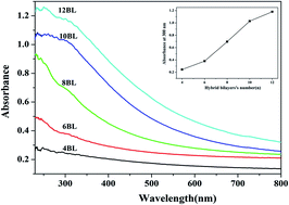
UV-visible absorption spectrometry was used to monitor the films growth on the quartz slides substrate. Fig. 1 shows the UV-visible spectra of GO based multilayer films on the quartz slide. Noticeably, the main absorption in the spectral range of 300–600 increased with the increase of hybrid-bilayer number. The adsorption band at 300 nm, which corresponds to the n–π* transitions of C[double bond, length as m-dash]O bonds at the edges of GO,24 shows a closed linear increase as the hybrid bilayer number increase. This result indicates that the multilayer films are uniformly deposited on the surface of quartz slide.
image file: c6ra15522g-f1.tif
Fig. 1 The UV-visible spectra of GO based multilayer films prepared on quartz slide.

The structural changes of the multilayer films on quartz slide before and after thermal reduction can be reflected in the Raman spectra. Fig. 2 shows the Raman spectra of multilayer films with 12 hybrid bilayers on quartz slide. The both of samples have two bands, namely the G-band (1593 cm−1) corresponding to an E2g mode of hexagonal graphite and is related to the vibration of sp2-bonds carbon atoms in graphite layers, and D-band (1347 cm−1) which is associated with vibration of carbon atoms with dangling bonds in the plane terminations of disordered carbons or glass carbons.25 The ratio of the intensity of the D and G bands (ID/IG) is a measure of disordered carbon, as expressed by the sp3/sp2 carbon ratio. The RGO based multilayer films shows higher ID/IG values (1.51) relative to that (1.31) of GO based multilayer films. The result is consistent with the previous report and the change suggests a decrease in the average size of the sp2 domains upon reduction of the GO.26 The increase of ID/IG can be usually explained as a decrease in the average size but an increase in the number of sp2 domains upon reduction.27


image file: c6ra15522g-f2.tif
Fig. 2 Raman spectra of GO based multilayer films with 12 hybrid bilayers prepared on quartz slide before (a) and after (b) the thermal reduction.

Table 1 shows the weight gain of FPU foams as a function of hybrid bilayer number. The weight gain of GO based multilayer films on FPU foams increased with the increase of hybrid bilayer number, indicating that the layer-by-layer film growth is carried out on the FPU foam surface. Notably, the weight gain decreased after the thermal reduction of multilayer films. As is well known, PEI and SA are both polymeric materials and can not volatilize during thermal reduction. The thermal reduction would cause the removal of some oxygen-containing groups on the plane of GO layers,26 resulting in the weight loss of LbL coating.

Table 1 Weight gain of GO and RGO coated FPU foams as a function of the hybrid bilayer number
Sample Hybrid bilayer numbers (n) SA/GO (mg mL−1) PEI (mg mL−1) Weight gain (%wt)
PU-0 0 0
PU-GO3 3 3/1 5 4.0
PU-GO7 7 3/1 5 12.4
PU-GO12 12 3/1 5 25.1
PU-RGO3 3 3/1 5 3.2
PU-RGO7 7 3/1 5 10.3
PU-RGO12 12 3/1 5 21.3


Fig. 3 shows the photographs of GO coated FPU foams before and after thermal reduction. Apparently, the color of coated FPU foams changes from dark brown to black before and after thermal reduction. In general, the GO nanosheets, prepared by chemical method, show the dark brown color, which would turn into black (the color of RGO) after thermal treatment.28 Accordingly, the change in color can be used as a macroscopic evidence of the reduction reaction.


image file: c6ra15522g-f3.tif
Fig. 3 Photographs of GO coated FPU foams before (upper row) and after (under row) the thermal reduction.

The corresponding surface morphologies of pristine and coated FPU foams are shown in Fig. 4. At the low magnification, the pristine FPU foam shows smooth and clean surface, whereas the coated FPU foams have rough surface due to the coverage of the LbL coating. At the high magnification, the surfaces of PU-GO7 and PU-GO12 sample are full of some wrinkles. These wrinkles are probably caused by thin coating of GO.28 After the thermal reduction, the observed wrinkling decreased, suggested by the images of PU-RGO7 and PU-RGO12 samples. The SEM images can confirm that GO and RGO based multilayer films are successfully deposited onto the surface of FPU foam.


image file: c6ra15522g-f4.tif
Fig. 4 SEM images of pristine and coated FPU foams: low magnification (the upper two rows) and high magnification (the under two rows).

Thermal stability

TGA test can provide direct information about the thermal stability and degradation mechanism by measuring the weight loss of sample as a function of temperature. The experimental TGA and DTG curves of pristine and coated FPU foams under nitrogen atmosphere are shown in Fig. 5, and the related data are shown in Table 2. Two thermal degradation steps can be observed for the pristine FPU foam. The first stage shows about 29% mass loss in the temperature range of 190–308 °C (peak maximum at 293 °C), which can be ascribed to the liberation of diisocyanates coming from depolymerization of the urethane and the bisubstituted of urea groups. The second step can be attributed to the decomposition of the remaining polyether chain.29 The pyrolysis of pristine FPU foam hardly leaves any char residue. Noticeably, all coated FPU foams show lower thermal stability than that of the pristine one at the temperature below 430 °C owing to the desorption of the adsorbed water and the degradation of PEI and SA component. However, all coated FPU foams show higher thermal stability and solid residue in the temperature range of 430–600 °C, which can be attributed to the good physical barrier effect of the multilayer films. Compared with that of GO coated samples, RGO coated FPU foams have less mass loss and more solid residue in the temperature range of 430–600 °C, indicating that the RGO coated samples have higher thermal stability than that of GO coated samples. In detail, the solid residue of PU-RGO7 at 600 °C is 4.20%, which is higher than 3.75% of PU-GO7. The reason is the better physical barrier effect of RGO mainly caused by the removal of the oxygenated functionalities of GO nanosheets during reduction.30 In addition, the char residue at 600 °C are 2.69%, 3.75% and 5.8% for PU-GO3, PU-GO7 and PU-GO12, and 3.01%, 4.20%, 6.01% for PU-RGO3, PU-RGO7 and PU-RGO12, respectively. These results reveal that the GO or RGO content in the multilayer films shows the dependence on the hybrid-bilayer number. In the DTG curves, it is clear that the maximum DTG peaks of GO-coated FPU foams become higher after the thermal reduction, indicating the faster degradation progress. This change can be ascribed to the higher thermal conductivity of RGO than that of GO.7
image file: c6ra15522g-f5.tif
Fig. 5 TGA (a) and DTG (b) curves of pristine and coated FPU foams.
Table 2 TGA data of pristine and coated FPU foams
Sample T−5% (°C) Tmax (°C) Char residue at 600 °C (%)
PU-0 257.0 387.6 0.70
PU-GO3 236.0 368.4 2.69
PU-GO7 225.0 378.6 3.75
PU-GO12 184.1 380.1 5.8
PU-RGO3 235.0 366.5 3.01
PU-RGO7 223.1 376.5 4.20
PU-RGO12 185.2 388.3 6.01


Flammability

Cone calorimeter is a routine bench scale fire test that simulates a developing fire scenario on a small specimen and is used to measure the forced burning fire performance of polymeric materials. Many combustion parameters such as heat release rate, total heat released, smoke production rate and total smoke released are directly indicating the potential fire threat of polymeric materials.

Heat release rate (HRR), total heat released (THR), smoke production rate (SPR) and total smoke released (TSR)

The heat release rate, especially for the peak heat release rate (PHRR) value, is usually considered to be key parameter to measure fire safety. The reduction in PHRR is important for fire safety, as PHRR represents the point in a fire where heat is likely to propagate further, or ignite adjacent objects. The heat release rate and total heat released curves of pristine and coated FPU foams were shown in Fig. 6(a) and (b). The corresponding data are listed in Table 3. The HRR curve of PU-0 consists of two peaks, which represent the pyrolysis of diisocyanate (first peak) and polyol (second peak), respectively.31,32 In the case of GO coated FPU foams, all samples have noticeable lower PHRR than that of PU-0. Furthermore, when the hybrid-bilayer number is higher, the reduction in PHRR is greater. PU-GO12 exhibits the lowest PHRR value among all samples, its peak is 202.9 kW m−2, which is highly 71.6% reduction than that (714.0 kW m−2) of PU-0. Additionally, the shape of the curves also exhibits some differences. PU-GO3 and PU-GO7 samples have two noticeable PHRR values, whereas PU-GO12 sample almost eliminates the second peak and largely extends the time it takes for complete combustion to occur (delayed effect). The PHRR value is not reduced but increased after the treatment of thermal reduction. PU-RGO12 sample exhibits two obvious PHRR values and its PHRR is even higher than that of PU-GO7. The rest of the samples with the treatment of thermal reduction also show similar results.
image file: c6ra15522g-f6.tif
Fig. 6 Heat release rate (a) and total heat released (b) curves of pristine and coated FPU foams.
Table 3 Cone data of pristine, GO and RGO coated FPU foams
Sample Time to ignition (s) Peak HRR (kW m−2) THR (MJ m−2) Peak SPR (m2 s−1) TSR (m2 m−2)
PU-0 2 714.0 15.7 0.199 312.9
PU-GO3 2 378.0 14.3 0.130 192.9
PU-GO7 2 231.2 14.0 0.0820 191.2
PU-GO12 3 202.9 18.5 0.0431 136.2
PU-RGO3 2 594.2 15.0 0.183 197.5
PU-RGO7 2 336.6 15.1 0.117 216.9
PU-RGO12 2 251.9 16.8 0.0960 269.3


The THR values of the coated FPU foams exhibit a small reduction except the PU-GO12 and PU-RGO12 samples, indicating that GO or RGO has little effect on the THR. GO and RGO can act as the physical barrier, which can effectively delay the transfer of heat, oxygen and the volatile gases, this process mainly reduce the heat release rate instead of the total heat released. In the case of PU-GO12 and PU-RGO12, their THR values are both higher than that of PU-0, probably because of additional high content of combustible component (PEI + SA) by multilayer films. In the previous work, our research group has carried out some researches on improving fire safety property of polymeric materials by the incorporation of graphene based materials. In general, RGO/polymer nanocomposites often have higher thermal stability and better fire safety property than that of GO/polymer nanocomposites due to the better thermal stability and physical barrier effect of RGO.6,30 In our present study, TGA analysis have also obtained the similar results. In theory, the better fire safety should be obtained for RGO coated FPU foams. However, the reality is just the opposite, described by the initial discussion of HRR results. Similar with other layered-nanoparticles,12,33 the layered-GO filled LbL coatings can act as the physical barrier to protect the underlying FPU foams. They can form a “tortuous path” to delay the diffusion of flammable pyrolytic gas products,34,35 and the proposed mechanism is depicted in Fig. S4(a) (ESI). Obviously, the quality of “tortuous path” has a close relationship with the thickness of LbL coatings. The higher is the thickness, the longer “tortuous path” to the barrier. As for GO filled LbL coating, its thickness is reduced after the thermal reduction, as shown in the Fig. S4(b) (ESI). Such a change is mainly caused by the removal of some oxygen-containing groups.26 Accordingly, the barrier effect becomes deteriorated when GO-filled LbL coating is transformed into RGO-filled LbL coating.

As shown in Fig. S5 (ESI), in the FTIR spectra of GO, several characteristic peaks of various oxygen-containing functionalities including C–O (1050 cm−1), C–OH (1260 cm−1), C[double bond, length as m-dash]O (1724 cm−1) and O–H (3423 cm−1) can be observed. Obviously, in the FTIR spectra of RGO, all peaks are very weak. That is because thermal reduction would remove some hydrophilic oxygen-containing groups, resulting in the reduced adhesion of GO nanosheets in the multilayer films. In essence, graphene based materials is a kind of graphite compound, which can be a component of smoke particles.7 Therefore, RGO is easier to release in air as smoke particles driven by the pyrolytic gas flow generated from matrix during the real burning. Such an assertion can be supported by the smoke yield and residual char structure in the cone tests. Smoke production rate (SPR) and total smoke production (TSR) are shown in Fig. 7(a) and (b), the related data are listed in Table 3. The meaning of TSR is cumulative smoke produced per unit mass of a sample. All coated FPU foams have lower values of peak SPR and TSR than that of PU-0, and the “delayed effect” in SPR is also observed for coated samples. However, the values of peak SPR and TSR are increased after the GO coated FPU foams treated with thermal reduction. PU-GO12 has the lowest TSR value, but the TSR value of PU-RGO12 becomes largest among all coated FPU foams. Such a dramatic difference should be ascribed to the loss of more amount of RGO layers as smoke particles when RGO coated FPU foams are burning. As can be seen from the photographs of char residue after cone test (in Fig. 8), there is no char residue for PU-0 and the coated samples leave more char residue. The char residues of PU-RGO7 and PU-RGO12 curl up much more than those of PU-GO7 and PU-GO12, indicating the formation of thinner char residue structure for RGO coated FPU foams. In summary, the worse fire safety property for RGO coated FPU foams can be ascribed to the loss of more amount of RGO layers during combustion and the reduced thickness of GO filled LbL coating.


image file: c6ra15522g-f7.tif
Fig. 7 Smoke production rate (a) and total smoke released (b) curves of pristine and coated FPU foams.

image file: c6ra15522g-f8.tif
Fig. 8 Photographs of char residue of pristine and coated FPU foams after cone test.

In the above discussion, it revealed that RGO have higher thermal stability and better physical barrier effect, but RGO filled coating has worse flame retardant property. Simultaneously, the present study gives the indication about the effective application of RGO based flame retardant multilayer films. It may be a good choice for increasing the thickness and adhesion of RGO nanosheets. For example, the target may be realized through the chemical grafting method, such as PEI grafted graphene or chitosan grafted graphene. The PEI or chitosan chains not only can increase the thickness of graphene layer but also improve the electrostatic adsorption capacity. Additionally, some researches have reported the preparation of RGO by the polyelectrolyte–exfoliation from GO nanosheets.36 And the RGO nanosheets physically decorated with polyelectrolyte may be also a good choice.

Conclusion

GO based LBL multilayer films were successfully deposited onto the surface of FPU foams using a hybrid bilayer method comprising of SA/GO and PEI. Subsequent thermal reduction were carried out to prepared RGO coated FPU foams. The ATR-FTIR and SEM were used to confirm that GO and RGO based multilayer films were successfully deposited on the FPU foam surface. TGA results showed that RGO coated FPU foams had higher thermal stability than that of GO coated FPU foam in the temperature range from 430 to 600 °C. All coated FPU foams showed the reduction in PHRR, peak SPR and TSR compared with that of the pristine FPU foam, indicating that GO or RGO based multilayer films have good physical barrier effect on FPU foams. The increasing PHRR, peak SPR and TSR values are observed for GO coated FPU foams after treating with thermal reduction. The worse fire safety property should be ascribed to the loss of more amount of RGO nanosheets and the reduced thickness of LbL coating. On the basis of detailed discussion, we pointed out that increasing thickness and adhesion of RGO nanosheets may be a good choice for effective flame retardant application of RGO based multilayer films.

Acknowledgements

The work was financially supported by the Fundamental Research Funds for the Central Universities, China University of Geosciences (Wuhan) (CUG160608), National Key Technology R&D Program (2013BAJ01B05), National Natural Science Foundation of China (51303167), National Natural Science Foundation of China (51276054) and National Natural Science Foundation of China (51303165).

References

  1. A. K. Geim and K. S. Novoselov, Nat. Mater., 2007, 6, 183–191 CrossRef CAS PubMed.
  2. A. H. CastroNeto, F. Guinea, N. M. R. Peres, K. S. Novoselov and A. K. Geim, Rev. Mod. Phys., 2009, 81, 109–208 CrossRef CAS.
  3. T. Ramanathan, A. A. Abdala, S. Stankovich, D. A. Dikin, M. Herrera-Alonso, R. D. Piner, D. H. Adamson, H. C. Schniepp, X. Chen, R. S. Ruoff, S. T. Nguyen, I. A. Aksay, R. K. Prud'homme and L. C. Brinson, Nat. Nanotechnol., 2008, 3, 327–331 CrossRef CAS PubMed.
  4. R. I. Jafri, N. Rajalakshmi and S. Ramaprabhu, J. Mater. Chem., 2010, 20, 7114–7117 RSC.
  5. J. S. Cheng, G. C. Zhang, J. H. Du, L. Y. Tang, J. Y. Xu and J. H. Li, J. Mater. Chem., 2011, 21, 3485–3494 RSC.
  6. C. L. Bao, L. Song, C. A. Wilkie, B. H. Yuan, Y. Q. Guo, Y. Hu and X. L. Gong, J. Mater. Chem., 2012, 22, 16399–16406 RSC.
  7. C. L. Bao, L. Song, X. Y. Xing, B. H. Yuan, C. A. Wilkie, J. L. Huang, Y. Q. Guo and Y. Hu, J. Mater. Chem., 2012, 22, 6088–6096 RSC.
  8. Y. Q. Guo, C. L. Bao, L. Song, B. H. Yuan and Y. Hu, Ind. Eng. Chem. Res., 2011, 50, 7772–7783 CrossRef CAS.
  9. X. Wang, S. Zhou, W. Y. Xing, X. M. Feng, L. Song and Y. Hu, J. Mater. Chem. A, 2013, 1, 4383–4390 CAS.
  10. O. C. Compton and S. B. T. Nguyen, Small, 2010, 6, 711–723 CrossRef CAS PubMed.
  11. Y. S. Kim, R. Davis, A. A. Cain and J. C. Grunlan, Polymer, 2011, 52, 2847–2855 CrossRef CAS.
  12. Y. S. Kim, R. Harris and R. Davis, ACS Macro Lett., 2012, 1, 820–824 CrossRef CAS.
  13. Y. S. Kim and R. Davis, Thin Solid Films, 2014, 550, 184–189 CrossRef CAS.
  14. B. Stevens, E. Dessiatova, D. A. Hagen, A. D. Todd, C. W. Bielawski and J. C. Grunlan, ACS Appl. Mater. Interfaces, 2014, 6, 9942–9947 CAS.
  15. W. Y. Sham and S. M. Notley, Langmuir, 2014, 30, 2410–2418 CrossRef PubMed.
  16. F. X. Xiao, J. W. Miao and B. Liu, J. Am. Chem. Soc., 2014, 136, 1559–1569 CrossRef CAS PubMed.
  17. S. T. Han, Y. Zhou, C. D. Wang, L. F. He, W. J. Zhang and V. A. L. Roy, Adv. Mater., 2013, 25, 872–877 CrossRef CAS PubMed.
  18. Z. P. Li, J. Q. Wang, X. H. Liu, S. Liu, J. F. Ou and S. G. Yang, J. Mater. Chem., 2011, 21, 3397–3400 RSC.
  19. I. Shakir, Z. Ali, J. Bae, J. Park and D. J. Kang, Nanoscale, 2014, 6, 4125–4130 RSC.
  20. H. L. Li, S. P. Pang, S. Wu, S. L. Feng, K. Müllen and C. Bubeck, J. Am. Chem. Soc., 2011, 133, 9423–9429 CrossRef CAS PubMed.
  21. Y. C. Li, Y. S. Kim, J. Shields and R. Davis, J. Mater. Chem. A, 2013, 1, 12987–12997 CAS.
  22. Y. S. Kim, Y. C. Li, W. M. Pitts, M. Werrel and R. Davis, ACS Appl. Mater. Interfaces, 2014, 6, 2146–2152 CAS.
  23. W. S. Hummers and R. E. Offeman, J. Am. Chem. Soc., 1958, 80, 1339 CrossRef CAS.
  24. J. I. Paredes, S. Villar-Rodil, A. Martinez-Alonso and J. M. D. Tascon, Langmuir, 2008, 24, 10560–10564 CrossRef CAS PubMed.
  25. M. L. Bras, S. Bourbigot, Y. L. Tallecand and J. Laureyns, Polym. Degrad. Stab., 1997, 56, 11–21 CrossRef.
  26. S. Stankovich, D. A. Dikin, R. D. Piner, K. A. Kohlhaas, A. Kleinhammes, Y. Jia, Y. Wuc, S. T. Nguyen and R. S. Ruoff, Carbon, 2007, 45, 1558–1565 CrossRef CAS.
  27. M. M. Lucchese, F. Stavale, E. H. M. Ferreira, C. Vilani, M. V. O. Moutinho and R. B. Capaz, Carbon, 2010, 48, 1592–1599 CrossRef CAS.
  28. Y. Liu, J. Ma, T. Wu, X. Wang, G. Huang, Y. Liu, H. Qiu, Y. Li, W. Wang and J. Gao, ACS Appl. Mater. Interfaces, 2013, 35, 10018–10026 Search PubMed.
  29. M. Zammarano, R. H. Krämer, R. Harris, T. J. Ohlemiller, J. R. Shields, S. S. Rahatekar, S. Lacerda and J. W. Gilman, Polym. Adv. Technol., 2008, 19, 588–595 CrossRef CAS.
  30. C. Bao, Y. Guo, L. Song and Y. Hu, J. Mater. Chem., 2011, 21, 13942–13950 RSC.
  31. R. H. Krämer, M. Zammarano, G. T. Linteris, U. W. Gedde and W. J. Gilman, Polym. Degrad. Stab., 2010, 95, 1115–1122 CrossRef.
  32. J. Lefebvre, B. Bastin, M. L. Bras, S. Duquesne, C. Ritter, R. Paleja and F. Poutch, Polym. Test., 2004, 23, 281–290 CrossRef CAS.
  33. Y. C. Li, Y. H. Yang, J. R. Shields and R. D. Davis, Polymer, 2015, 56, 284–292 CrossRef CAS.
  34. X. Wang, L. Song, H. Yang, W. Xing, H. Lu and Y. Hu, J. Mater. Chem., 2012, 22, 3426–3431 RSC.
  35. Y. Shi, X. Qian, K. Zhou, Q. Tang, S. Jiang, B. Wang and R. K. Yuen, Ind. Eng. Chem. Res., 2013, 52, 13654–13660 CrossRef CAS.
  36. S. Zhang, Y. Shao, H. Liao, M. H. Engelhard, G. Yin and Y. Lin, ACS Nano, 2011, 5, 1785–1791 CrossRef CAS PubMed.

Footnote

Electronic supplementary information (ESI) available. See DOI: 10.1039/c6ra15522g

This journal is © The Royal Society of Chemistry 2016
Click here to see how this site uses Cookies. View our privacy policy here.