Polyvinylidene fluoride hollow fiber mixed matrix membrane contactor incorporating modified ZSM-5 zeolite for carbon dioxide absorption

Afsaneh Shirzadeh-Gharacheh and Masoud Rahbari-Sisakht*
Department of Chemical Engineering, Islamic Azad University, Gachsaran Branch, Gachsaran, Iran. E-mail: rahbari@iaug.ac.ir; rahbarisisakht@gmail.com; Fax: +98 74 3233 2003; Tel: +98 74 3233 3533

Received 13th June 2016 , Accepted 3rd August 2016

First published on 3rd August 2016


Abstract

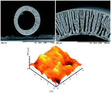
ZSM-5 (Zeolite Socony Mobil-5) was modified using hexadecyltrichlorosilane (HDTS) to increase its hydrophobicity. The modified ZSM-5 was applied in different concentrations (0, 0.25, 0.5 and 1 wt% of solution) in the polyvinylidene fluoride (PVDF) (18 wt% of solution) spinning dope to fabricate hollow fiber mixed matrix membranes for CO2 absorption in a gas–liquid membrane contactor. The properties of the fabricated membranes, including gas permeance, mechanical stability and wetting resistance, were examined. The morphologies of the membrane structures and surface roughness were studied using SEM and AFM, respectively. The SEM images showed that the HFM structure was changed from sponge-like to finger-like with big macrovoids. The AFM analysis showed that the outer surface roughness of the membrane was increased by increasing the ZSM-5 concentration in the spinning dope. By the addition of ZSM-5 zeolite to the polymer, the dope gas absorption performance of the fabricated membranes was improved. The optimum ZSM-5 concentration of 0.5 wt% of solution for the gas–liquid contacting process was obtained. The maximum absorption flux of 1.65 × 10⁻³ mol m−2 s−1 was achieved at a liquid flow rate of 300 ml min−1 for the composite membrane fabricated using the optimum amount of ZSM-5, which was about 100% more than the plain PVDF membrane flux.

1. Introduction

One of the grave environmental problems in the world is the global warming that is caused mainly by greenhouse gases. It has been reported that more than eighty percent of energy consumption in the world is provided by fossil fuels.1 Burning of fossil fuels increases atmospheric carbon dioxide (CO2) levels, which is the major greenhouse gas. Hollow fiber gas–liquid membrane contactor systems (HFMC) for CO2 absorption and stripping have been widely developed by several researchers.2–8

Different types of polymeric materials, such as polyvinylidene fluoride (PVDF),9–13 polysulfone (PSf),3,8,14,15 polyetherimide (PEI)16–19 and polyethersulfone (PES)20,21 have been used to fabricate hollow fiber membranes via the phase inversion method. Among them, PVDF is most preferred because of its higher hydrophobicity, which is an important parameter in the gas–liquid contacting process. Despite the advantages of the hollow fiber membrane contactor, there are some drawbacks. Partial pore wetting is one of the obstacles in the MC process that can increase the mass transfer resistance.22,23 In our previous study,14 it was observed that the CO2 absorption flux of a PSf hollow fiber membrane was decreased to about 36.5% of its initial rate in the initial 25 h of operation.

In general, the rate of the phase inversion influences the structure of the membrane.16 A fast demixing rate of solvent/non-solvent forms a finger-like structure in the HFMs and a slow phase inversion makes a sponge-like structure.24 The demixing rate of solvent/non-solvent can be changed by employing additives to the casting solutions. Mansourizadeh and Ismail25 used glycerol, phosphoric acid (PA), ethanol and polyethylene glycol (PEG-400) as additives in the PVDF solution. The morphology study showed that by the addition of PEG-400, glycerol and PA to the spinning dope, the sponge-like structure was formed, owing to the high viscosity of the solutions. Also, the membrane fabricated using glycerol showed larger pore size and higher gas absorption flux. Bakeri et al.26 used water, methanol, ethanol, glycerol and acetic acid as additives in the polyetherimide (PEI) dope to fabricate PEI HFM. The results demonstrated that using water as the additive decreased the thermodynamic stability and increased the viscosity of the solution, which resulted in a membrane with a thin skin layer and a sublayer with a sponge-like structure. The HFM fabricated using methanol as the additive in the spinning dope presented the highest absorption flux. Ethanol, glycerol and acetone were employed as non-solvent additives in the PEI casting solution.16 Ethanol in the PEI solution presented the HFM structure with a sublayer, with finger-like macrovoids starting from the inner and outer surfaces of the HFM and expanding to the middle section of the HFM. Formation of this structure resulted in a larger pore size and higher CO2 absorption rate than the other PEI HFMs.

Mixed matrix membranes (MMMs), which are fabricated using polymer–inorganic materials, can be applied as an alternative to polymeric membranes. Fabricated mixed matrix membranes by other researchers showed appropriate properties, such as permeability, hydrophobicity and mechanical stability.27–30 The application of the mixed matrix membrane for the gas–liquid contacting process has rarely been investigated. Rezaei et al.27 fabricated porous PVDF-hydrophobic montmorillonite nano-clay (MMT) mixed matrix membranes using different concentrations of MMT in the spinning dope. By the addition of MMT in the spinning dope, a thick sponge-like structure with thin finger-like pores close to the outer surface of the HFMs was formed. By increasing the MMT concentration, the length of the finger-like pores was increased, which can be the logical reason for the higher permeability and lower mass transfer resistance of MMMs, compared to the control PVDF HFM. Their results showed a significant increase in the surface hydrophobicity, gas permeability and critical entry pressure of water (CEPw) of the membranes with increasing the MMT concentration. Also, the CO2 absorption flux of the membrane fabricated using 5 wt% of MMT was 56% higher than the plain PVDF membrane. Dasht Arzhandi et al.31 used different concentrations of MMT to fabricate PVDF MMMs for CO2 stripping from water. The results showed that the phase inversion rate was increased by the addition of MMT, which contributed to the formation of HFMs with longer finger-like structures and higher surface porosities. The MMM fabricated using 5 wt% of MMT showed the stripping flux of 38% higher than the plain PVDF hollow fiber, under the same operating conditions. Fosi-Kofal et al.32 fabricated PVDF composite HFM by using different concentrations of hydrophobic CaCO3 nanoparticles in the polymer matrix. They observed that with the addition of the hydrophobic nanoparticles in the spinning dope, a tighter finger-like structure was formed in the fabricated MMMs, compared to the plain PVDF membrane. They found that by increasing the CaCO3 concentration in the spinning dope, the membrane hydrophobicity and (CEPW) of the membranes were increased considerably. According to their results, the MMM fabricated using 3.6 wt% of nano-particles as additive showed the maximum CO2 absorption flux of 1.52 × 10⁻³ mol m−2 s−1 at 300 ml min−1 absorbent flow rate.

ZSM-5 is an aluminosilicate zeolite with a high silica and low aluminium content. ZSM-5 has been commonly used as membrane fillers, selective absorbents and catalysts.33–37 ZSM-5 modification was conducted by Ogawa et al.36 where octadecyltrichlorosilane (OTS) was used for H-ZSM-5 treatment. Their results showed that the OTS treated H-ZSM-5 was an effective catalyst for the hydrolysis of water-insoluble esters in the toluene–water solvent system.

Han et al.37 modified ZSM-5 using octyltrichlorosilane (OTS), decyltrichlorosilane (DTS), dodecyltrichlorosilane (DDTS) and hexadecyltrichlorosilane (HDTS). According to their results, with increasing the alkyl chain length of trichlorosilane, the hydrophobicity of modified ZSM-5 increased and a hydrophobic layer at the particles surface was observed after modification. The water contact angle of ZSM-5 was changed from 12.5° to 160° for unmodified ZSM-5 and ZSM-5 modified using HTDS, respectively, at a temperature of 25 °C.

In this study, the surface hydrophobicity of ZSM-5 zeolite was modified using hexadecyltrichlorosilane (HDTS). Then, the modified ZSM-5 was used as an additive in the spinning dope to fabricate the PVDF/ZSM-5 hollow fiber composite membrane. The fabricated membranes were applied in a gas–liquid membrane contactor system for CO2 absorption. To the best of our knowledge, the ZSM-5 zeolite treated by this method has never been used before for gas–liquid membrane contactor application for CO2 absorption.

2. Experimental

2.1 Materials

Commercial PVDF polymer pellets (Kynar@ 740) were supplied by Arkema Inc., Philadelphia, (USA). 1-Methyl-2-pyrrolidone (N-methyl-2-pyrrolidone, NMP, >99.5%, purchased from Merck) was used as solvent without further purification. ZSM-5 zeolite was obtained from Tianjin Hutong Global Trade Co., Ltd. (China). Hexadecyltrichlorosilane (HDTS) was purchased from Alfa Aesar. Toluene was purchased from Merck and was used as received.

2.2 ZSM-5 modification

ZSM-5 zeolite was treated using HDTS via the method used by Han et al.37 For this purpose, ZSM-5 particles were dried at a temperature of 25 °C for 5 h. Then, 5 g ZSM-5 particles were dispersed in 25 g toluene and stirred at room temperature for 1 h. To the above mixture, 4 g HDTS were added, and then the mixture was refluxed for another 12 h at 70 °C. In order to remove the unreacted HDTS, this solution was filtered and washed several times with toluene. The obtained particles were subsequently dried in an oven at 110 °C for 5 h to remove the residual solvent.

2.3 Hollow fiber membrane fabrication

Modified ZSM-5 in amounts of 0.25, 0.5 and 1.0 wt% of solution, were dispersed in the solvent and sonicated for 45 min at 45 °C to break up the zeolite agglomerates. The PVDF polymer in pellet form was dried at 70 °C in a vacuum oven for 24 h to remove the moisture. Then, PVDF of 18 wt% of solution was gradually added to the suspensions of ZSM-5 in the NMP mixture under strong stirring until homogeneous solutions were achieved. The prepared solutions were ultra-sonicated and degassed at ambient temperature for 24 h before spinning to remove air bubbles in the solutions. The spinning dope composition is presented in Table 1. The hollow fiber spinning method by the phase inversion process was explained previously, in detail.38 The fabricated hollow fibers were immersed in water for 3 days with daily changing of the water to remove the remaining NMP and the non-solvent additive. The prepared fibers were then dried at room temperature. The spinning parameters are presented in Table 2.
Table 1 Compositions of the spinning solutions
Solution name NMP (wt%) ZSM-5 (wt%) PVDF (wt%) Solution viscosity (centipoises)
M1 82 0.0 18 2815.3
M2 81.75 0.25 18 2793.1
M3 81.5 0.50 18 2785.2
M4 81 1.0 18 2781.1


Table 2 Hollow fiber spinning parameters
Dope extrusion rate (ml min−1) 4.50
Bore fluid composition (wt%) NMP/water (80/20)
Bore fluid rate (ml min−1) 1.55
Coagulation medium Tap water
Air gap length (cm) 0.0
Spinneret dimension, o.d./i.d. (mm) 1.20/0.55
Temperature of coagulant (°C) 25


2.4 Hollow fiber membrane characterization

Spun PVDF hollow fiber membrane properties, regarding the average pore radius, effective surface porosity, overall porosity, water contact angle, collapsing pressure, CEPw and nitrogen (N2) permeation, were studied, which have been methodically explained in our previous studies.5,10,39 In order to obtain the average pore size and the effective surface porosity, the nitrogen permeation test was carried out based on the method of Li et al.,40 which was explained in our previous studies.5,10 The water contact angles of the prepared membranes were measured to acquire information about the outer surface hydrophobicity of the membranes.9,10 In order to determine the wetting resistance of the fabricated membranes, the critical entry pressure of water (CEPw) was measured5,10 (CEPw is measured as the pressure at which the first drop of water is discerned on the outer surface of the membrane). The gravimetric method was used to measure the overall porosities of the membranes.5,10 The collapsing pressure of HFMs was measured to evaluate the membranes' mechanical stability.10 The morphology of the cross-section, inner surface and outer surface of the fabricated membranes were studied using scanning electron microscopy (SEM, tabletop microscope, TM3000) and the outer surface EDX analysis was conducted using Oxford Instruments Swift ED3000, Analytical Ltd., USA. Khayet et al.41 presented a method to obtain the membrane roughness parameter (Ra). In this study, their method was applied to measure the mean roughness parameter of the outer surface of the membranes by atomic force microscopy (AFM) using AFM equipment (SPA 300 HV, Japan). Viscosities of polymeric solutions were determined using viscometer model EW-98965-40, Cole Parmer, USA.

2.5 Carbon dioxide absorption test

The physical CO2 absorption for the fabricated HFs was carried out in a gas–liquid membrane contactor system. A stainless steel module with an effective length of 18.0 cm was prepared. Ten hollow fiber membranes were randomly placed in a membrane module. The specifications of the fabricated module are shown in Table 3. Pure CO2 was applied on the lumen side of the hollow fiber membranes and liquid absorbent (distilled water) on the shell side of the module. A counter-current mode for the gas and liquid phase was used in the contactor module. The constant gas flow rate of 200 ml min−1 and liquid flow rate ranging from 50 to 300 ml min−1, were applied and were controlled using the control valves and flex-meters. The stable gas side pressure of 1 × 10⁵ Pa (1 bar) was set. In order to prevent bubble formation in the liquid absorbent, the liquid side pressure was set at 0.2 × 10⁵ Pa (0.2 bar), higher than that of the gas side.42 The outlet CO2 concentration in the liquid stream was measured by the titration method, using 0.05 M sodium hydroxide (NaOH) solution as the titrant and phenolphthalein solution as the indicator. In order to reach a steady state condition, all the tests were conducted for 30 min before titration. The experimental apparatus for CO2 absorption was presented in previous works.5,10,39
Table 3 Detailed specifications of the contactor module
Module i.d. (mm) 15
Module length (mm) 250
Fiber o.d. (mm) 0.9 to 1.0
Fiber i.d. (mm) 0.45 to 0.50
Effective fiber length (mm) 180
Number of fibers 10


3. Results and discussion

3.1 Scanning electron microscope (SEM) images

Generally, membrane structure is affected by the phase inversion rate and composition of the casting solution. Wang et al.43 and Dindore, et al.44 stated that the rapid phase inversion rate causes the formation of porous asymmetric membranes. In order to observe the morphologies of the fabricated membranes by SEM, the cross-sections, the inner surfaces and the outer surfaces of the membranes were studied. The PVDF membranes showed outer diameters ranging from 0.70 to 0.90 mm, inner diameters ranging from 0.45 to 0.5 mm and the wall thickness ranging from 0.225 to 0.250 mm. Fig. 1–4 illustrate the cross sectional structures, inner and outer surface morphologies of the fabricated hollow fiber membranes. As can be seen, all the fabricated hollow fibers presented similar dimensions, due to using similar dope extrusion rates and bore fluid flow rates. In general, adding non-solvent additives to the spinning solution increases solvent/non-solvent demixing, resulting in the formation of finger-like structures.45 Also, it was proven that the decrease in viscosity reduces the thermodynamic stability and precipitates the demixing rate of solvent/non-solvent during phase inversion.46 From Fig. 1(A1 and A2), the PVDF hollow fiber membrane that was fabricated without additive shows a thick sponge-like structure in the center of the hollow fiber, with thin finger-like structures close to the outer surface. The formation of a thick sponge-like layer in the middle of the hollow fiber is due to less diffusion of water into this part of the membrane. By addition of ZSM-5 zeolite in the spinning dope, the thickness of the sponge-like structure decreased and longer finger-like structures were formed (see Fig. 2–4(A1 and A2)). The longer finger-like structures of mixed matrix membranes were formed because the lower viscosity (see Table 1) of their polymer dope resulted in less thermodynamic stability and faster phase inversion by addition of zeolite.47
image file: c6ra15375e-f1.tif
Fig. 1 SEM image of plain PVDF membrane (M1), (A1 and A2) cross-section, (B) inner surface, (C) outer surface.

image file: c6ra15375e-f2.tif
Fig. 2 SEM image of PVDF + 0.25 wt% ZSM-5 (M2), (A1 and A2) cross-section, (B) inner surface, (C) outer surface.

image file: c6ra15375e-f3.tif
Fig. 3 SEM image of PVDF + 0.50 wt% ZSM-5 (M3), (A1 and A2) cross-section, (B) inner surface, (C) outer surface.

image file: c6ra15375e-f4.tif
Fig. 4 SEM image of PVDF + 1.0 wt% ZSM-5 (M4), (A1 and A2) cross-section, (B) inner surface, (C) outer surface.

The SEM images of the inner surfaces of the membranes (Fig. 1–4(B)) show skinless structures, due to using a high concentration of solvent in the bore fluid mixture (80% NMP). It was reported that using solvent in the bore fluid prevents the formation of a skin layer at the hollow fiber membrane inner surface.39,48,49 Fig. 1–4(C) show that the outer surfaces of the hollow fiber membranes are not as rough as the inner surfaces, demonstrating skin layer formation at the outer surface, due to using water as the external coagulant and consequently, faster solvent/non-solvent demixing. As can be seen by the addition of ZSM-5 in the polymer dope, particle agglomeration was observed at the outer surface of the membranes (white spots).

3.2 Atomic force microscope (AFM) analysis

Fig. 5 illustrates the 3D AFM images of the outer surfaces of the membranes. The obtained mean roughness parameters (Ra) are reported in Table 4. The mean roughness parameter (Ra) increases with an increase in ZSM-5 concentration in the spinning dope. It is associated with the presence of ZSM-5 particles on the membrane surface and the decrease in polymer dope viscosity. It is interesting that the parallel nodular alignment is apparent for membrane M1 and it becomes more ambiguous as the ZSM-5 concentration increases, probably due to increasing particle concentration on the membrane's outer surface. A similar trend was observed by Rezaei et al.,50 when montmorillonite nano-clay was used as an additive in the polymer dope to fabricate the PVDF/montmorillonite composite membrane for CO2 absorption. Nevertheless, it was proven that the roughness parameter is not the absolute roughness quantity and it depends on the torsion and the AFM tip size.51
image file: c6ra15375e-f5.tif
Fig. 5 AFM 3D images of the outer surfaces of PVDF hollow fiber membranes.
Table 4 Characteristics of PVDF hollow fiber membranes
Membrane name Average pore size (nm) Effective surface porosity ε/Lp (×102 m−1) CEPw (×105 Pa) Overall porosity (%) Collapsing pressure (×105 Pa) Water contact angle (°) Roughness (Ra)
M1 25.18 ± 2.35 1250 ± 3.40 4.00 ± 0.25 72.21 ± 1.33 8.50 ± 0.50 81.23 ± 0.25 4.23
M2 33.42 ± 3.05 2660 ± 4.23 3.50 ± 0.25 74.05 ± 0.48 6.50 ± 0.50 84.50 ± 0.63 6.65
M3 36.23 ± 1.16 2983 ± 2.61 3.50 ± 0.25 75.64 ± 2.81 6.00 ± 0.50 87.23 ± 1.16 7.14
M4 22.15 ± 0.78 2053 ± 1.37 5.50 ± 0.25 77.35 ± 1.50 6.50 ± 0.50 89.50 ± 0.82 8.02


3.3 Structure of PVDF HFM

Modified ZSM-5 zeolite with different loadings was applied in the polymer dopes to fabricate porous PVDF mixed matrix membranes with improved structures for gas absorption purposes. The structure and properties of prepared membranes, such as gas permeability, CEPw, collapsing pressure, water contact angle and overall porosity were studied. The characterization findings are presented in Table 4.

Generally, the overall porosities of the asymmetric membranes strangely depend on the spinning solution composition. From Table 4, the overall porosities of the prepared hollow fibers are high enough for the gas–liquid contacting process, which can be due to the low polymer concentration in the spinning dope. By increasing the ZSM-5 concentration in the polymer solutions, the overall porosity increases, which can be explained by the change in the membrane morphology from the sponge-like to the finger-like structure.

The mechanical stability of the fabricated membranes was studied using a collapsing pressure experiment. As can be seen in Table 4, the PVDF membrane prepared without additive in the spinning solution presented the highest collapsing pressure. The addition of ZSM-5 in the spinning dope formed the membrane structure with big macrovoids and resulted in lower mechanical stability. In fact, the sponge-like structure of membrane M1 governed the mechanical stability of this membrane. It was mentioned in the CO2 absorption test (see part 2.5) that the liquid phase pressure is 0.2 bar more than the gas phase pressure, therefore, the obtained mechanical stabilities are appropriate in this study. Although, the pressure gradient between gas phase and liquid absorbent is much less than obtained for mechanical stabilities, the hollow fibers with high mechanical stability are more suitable for unsteady operating conditions.

In order to study the surface hydrophobicity and wetting resistance of the fabricated hollow fibers, contact angle measurements and critical water entry pressure (CEPw) experiments were carried out. In fact, in the gas absorption and stripping process using MC, the membrane pores should be gas filled to prevent increasing mass transfer resistance. Hence, the hollow fiber membrane with high wetting resistance is preferred for these processes. The sessile drop method is usually used as an uncomplicated and suitable method for membrane surface contact angle measurement.10,31,52 The contact angle of the outer surface of the fabricated PVDF membranes increased from 81.23 of M1 to 89.50 of M4 (see Table 4). This can be explained reasonably by the enhancement of the effective solid surface area and interfacial energy between the solid and liquid by using the hydrophobic ZSM-5 as an additive in the polymer dope.53 It can be said that the addition of the ZSM-5 zeolite in the solution decreases the surface energy of the hollow fiber membrane. A similar trend was observed for the surface modified PVDF membrane when the hydrophobic surface modifying macromolecule (SMM) was applied as the additive in the spinning dope.9 It was reported that the solid surfaces with lower surface energies show higher contact angles.54 Also, considering Fig. 1–4(C), hydrophobic ZSM-5 particle agglomeration was observed at the membranes' outer surfaces, which can increase the outer surface contact angle. Another reasonable explanation for contact angle enhancement is the formation of HF membranes with rougher surfaces, by increasing the ZSM-5 concentration in the polymer dope.54–56 It was substantiated that membrane hydrophobicity and pore size affected membrane pore wetting.57 From Table 4, by increasing the pore size, CEPw of the membranes decreased and the highest CEPw of 5.5 bar was achieved for the membrane with the smallest pore size and highest surface hydrophobicity (M4). Furthermore, the surprising decrease of the CEPw of membranes M1 to M3 occurred gradually with increasing membrane hydrophobicity, which can be related to the enlargement of the membranes' pore sizes. It can be concluded that both membrane pore size and surface hydrophobicity are affected by the membrane wetting resistance, which should be controlled.

Fig. 6 shows the gas (N2) permeance of the fabricated hollow fiber membranes as a function of mean pressure. The solid lines show the best linear fitting of the permeance results. Mean pore size and effective surface porosity calculated from the gas permeation tests have been provided in Table 4. The calculation method was presented in our previous works.3,5,10,58,59 It is clear that the gas permeance improved with the addition of ZSM-5 to the polymer solutions. The maximum gas permeance was achieved by membrane M3, due to the finger-like structure and bigger pore size of this membrane. N2 permeance of membrane M1 is lower than membrane M4, even though its pore size is bigger; this can be attributed to the thick sponge-like structure of membrane M1. The higher gas permeance of composite membranes is related to the formation of finger-like macrovoids in their structures.


image file: c6ra15375e-f6.tif
Fig. 6 N2 permeance of fabricated membranes as a function of mean pressure.

In order to prove the existence of ZSM-5 zeolite in the membrane structure, the EDX test was conducted. The EDX results for the outer surfaces of fabricated membranes are presented in Table 5. Comparing M1 and other mixed matrix membranes, the F content of MMMs is lower than for the M1 membrane; this is because F does not exist in ZSM-5 particles. As can be seen from Table 5, by increasing the ZSM-5 concentration, the Si and Al weight percentages were increased. This confirms the exposure of ZSM-5 on the outer membrane surface, which increased the hydrophobicity of the membrane surface, as presented in Table 4.

Table 5 Elemental composition of the membranes' outer surfaces
Element % Weight
M1 M2 M3 M4
F 58.62 55.37 55.10 54.59
C 41.38 40.85 39.66 36.89
O 3.05 3.62 4.74
Si 0.4 0.85 1.95
Al 0.33 0.77 1.83


3.4 Carbon dioxide absorption results

A physical CO2 absorption experiment using distilled water as liquid absorbent was conducted at 25 °C in a gas–liquid membrane contactor. Distilled water was applied as the liquid absorbent on the module shell side in contact with the hollow fiber's outer surface and pure CO2 on the lumen side of the hollow fiber membranes, concurrently. CO2 absorption performance of the fabricated hollow fibers was compared and the results are presented in Fig. 7. As can be seen, the CO2 absorption rate of all membranes was increased by increasing the liquid phase flow rate. It was reported that in physical gas absorption using a gas–liquid membrane contactor, the liquid phase boundary layer controlled mass transfer and there was no resistance on the gas phase due to using pure gas.40,60 Enhancement of the liquid phase flow rate can decrease the liquid boundary layer, consequently decreasing the mass transfer resistance.
image file: c6ra15375e-f7.tif
Fig. 7 CO2 absorption flux vs. liquid flow rate of PVDF hollow fiber membranes.

From Fig. 7, CO2 absorption flux increased with the addition of ZSM-5, with particle concentration from 0 to 0.5 wt% (M1 to M3). By increasing ZSM-5 concentration to 1 wt% (M4), the absorption flux decreased significantly. The decline of membrane M4 absorption flux can be related to the agglomeration of ZSM-5 particles on the membrane surface, resulting in the reduction of the effective surface porosity of the M4 membrane. The effective surface porosity of this membrane is reported in Table 4 and confirms this explanation. Consequently, by decreasing the effective surface porosity of this membrane, the contact area between gas and liquid was decreased and therefore, the gas absorption flux of this membrane decreased. Among the fabricated membranes, the membrane M3 showed the highest absorption flux. From Table 4, the effective surface porosity of this membrane is higher than others. Also, due to the finger-like structure of this membrane, its gas permeability was higher than other fabricated membranes. Therefore, the optimum ZSM-5 concentration of 0.5 wt% of solution is appropriate for the gas–liquid contacting process. The maximum absorption flux of 1.65 × 10⁻³ mol m−2 s−1 was achieved at liquid flow rate of 300 ml min−1 for membrane M3, which was about 100% more than membrane M1.

In Table 6, comparisons are made between the CO2 absorption fluxes of the mixed matrix membrane fabricated in this work and those reported in other studies. The M3 membrane fabricated in this work shows the best CO2 flux, except for the PVDF HFM fabricated using 6 wt% of hydrophobic SMM (number 6 in Table 6). It should be noted that membrane M3 (fabricated in this work) was fabricated using only 0.5 wt% of additive, while for fabrication of membrane number 6, 6 wt% of additive was used. Therefore, it is expected that membrane number 6 would show higher water contact angle and gas permeance, resulting in higher absorption flux.

Table 6 Comparison of the absorption flux of membrane M3 (0.5 wt% ZSM-5 in the spinning dope) with in-house made and commercial membranes
Number Polymer material Additive CO2 flux (mol m−2 s−1) Liquid absorbent flow rate (ml min−1) Reference
a Surface modifying macromolecule.b General montmorillonite.c Commercial membranes.
1 PVDF ZSM-5 1.65 × 10⁻³ 300 This work
2 PVDF SMMa 7.7 × 10⁻⁴ 300 10
3 PVDF LiCl 6.14 × 10⁻⁴ 300 45
4 PVDF Montmorillonite 1.59 × 10⁻³ 200 27
5 PVDF Gmb 9.93 × 10⁻⁴ 300 28
6 PVDF 6 wt% SMM 5.4 × 10⁻³ 300 9
7 PSf Glycerol 2.90 × 10⁻⁴ 200 5
8 PSf SMM 5.80 × 10⁻⁴ 300 14
9 PPc 1.950 × 10⁻⁴ 300 61
10 PTFEc 3.70 × 10⁻⁴ 300 61
11 PEI Ethanol 8.80 × 10⁻⁴ 300 16


Membrane M1 fabricated without ZSM-5 particles showed the lowest gas absorption flux among prepared membranes, even though this membrane wetting resistance was higher than for other membranes. As can be seen from Table 4 and Fig. 6, the effective surface porosity and gas permeance of membrane M1 were lower than the fabricated mixed matrix membranes, hence, this membrane showed lower absorption flux. Therefore, it can be concluded that gas permeability and surface porosity are key parameters in the gas–liquid contacting process.

4. Conclusion

Modified ZSM-5 zeolite was applied in the PVDF spinning dope to fabricate mixed matrix hollow fiber membranes for CO2 absorption in a gas–liquid membrane contactor. The properties of the fabricated membranes, including gas permeance, mechanical stability and wetting resistance, were examined. The morphologies of the membrane structures and surface roughness were studied using SEM and AFM, respectively. The SEM images showed that the HFM structure was changed from sponge-like to finger-like with big macrovoids. The AFM analysis of the membranes' surfaces showed an increase in the membranes' surface roughness, due to the agglomeration of ZSM-5 particles on the membrane surface, resulting in the enhancement of the membrane surface contact angle. By the addition of ZSM-5 zeolite to the doped polymer, the gas absorption performance of the fabricated membranes was improved. The optimum ZSM-5 concentration of 0.5 wt% of solution for the gas–liquid contacting process was obtained. The maximum absorption flux of 1.65 × 10⁻³ mol m−2 s−1 was achieved at a liquid flow rate of 300 ml min−1 for the composite membrane that was fabricated using the optimum amount of ZSM-5.

References

  1. T. C. Merkel, H. Lin, X. Wei and R. Baker, J. Membr. Sci., 2010, 359, 126–139 CrossRef CAS.
  2. G. Bakeri, A. F. Ismail, M. Rahimnejad and T. Matsuura, Chem. Eng. Res. Des., 2014, 92, 1381–1390 CrossRef CAS.
  3. F. Korminouri, M. Rahbari-Sisakht, T. Matsuura and A. F. Ismail, Chem. Eng. J., 2015, 264, 453–461 CrossRef CAS.
  4. F. Korminouri, M. Rahbari-Sisakht, D. Rana, T. Matsuura and A. F. Ismail, Sep. Purif. Technol., 2014, 132, 601–609 CrossRef CAS.
  5. M. Rahbari-Sisakht, A. F. Ismail and T. Matsuura, Sep. Purif. Technol., 2012, 86, 215–220 CrossRef CAS.
  6. W. Rongwong, S. Boributh, S. Assabumrungrat, N. Laosiripojana and R. Jiraratananon, J. Membr. Sci., 2012, 392–393, 38–47 CrossRef CAS.
  7. D. deMontigny, P. Tontiwachwuthikul and A. Chakma, J. Membr. Sci., 2006, 277, 99–107 CrossRef CAS.
  8. M. Rahbari-Sisakht, F. Korminouri, D. Emadzadeh, T. Matsuura and A. F. Ismail, RSC Adv., 2014, 4, 59519–59527 RSC.
  9. M. Rahbari-Sisakht, A. F. Ismail, D. Rana, T. Matsuura and D. Emadzadeh, Sep. Purif. Technol., 2013, 116, 67–72 CrossRef CAS.
  10. M. Rahbari-Sisakht, A. F. Ismail, D. Rana and T. Matsuura, J. Membr. Sci., 2012, 415–416, 221–228 CrossRef CAS.
  11. R. Naim and A. F. Ismail, Sep. Purif. Technol., 2013, 115, 152–157 CrossRef CAS.
  12. N. Ghasem, M. Al-Marzouqi and A. Duidar, Sep. Purif. Technol., 2012, 98, 174–185 CrossRef CAS.
  13. S. Rajabzadeh, S. Yoshimoto, M. Teramoto, M. Al-Marzouqi and H. Matsuyama, Sep. Purif. Technol., 2009, 69, 210–220 CrossRef CAS.
  14. M. Rahbari-Sisakht, A. F. Ismail, D. Rana and T. Matsuura, Sep. Purif. Technol., 2012, 99, 61–68 CrossRef CAS.
  15. M. Rahbari-Sisakht, A. F. Ismail, D. Rana, T. Matsuura and D. Emadzadeh, Sep. Purif. Technol., 2013, 108, 119–123 CrossRef CAS.
  16. M. Rahbari-Sisakht, A. F. Ismail, D. Rana and T. Matsuura, Sep. Purif. Technol., 2012, 98, 472–480 CrossRef CAS.
  17. G. Bakeri, T. Matsuura, A. F. Ismail and D. Rana, Sep. Purif. Technol., 2012, 89, 160–170 CrossRef CAS.
  18. R. Naim, A. F. Ismail, N. B. Cheer and M. S. Abdullah, Chem. Eng. Res. Des., 2014, 92, 1391–1398 CrossRef CAS.
  19. Z. A. Tarsa, S. Hedayat and M. Rahbari-Sisakht, Journal of Membrane Science and Research, 2015, 1, 118–123 Search PubMed.
  20. G. Bakeri, A. F. Ismail, M. R. DashtArzhandi and T. Matsuura, J. Membr. Sci., 2015, 475, 57–64 CrossRef CAS.
  21. S. A. Hashemifard, T. Matsuura, A. F. Ismail, M. Rezaei Dasht Arzhandi, D. Rana and G. Bakeri, Chem. Eng. J., 2015, 281, 970–980 CrossRef CAS.
  22. R. N. Hassanlouei, R. Pelalak and A. Daraei, Int. J. Greenhouse Gas Control, 2013, 16, 233–240 CrossRef CAS.
  23. M. Mavroudi, S. P. Kaldis and G. P. Sakellaropoulos, J. Membr. Sci., 2006, 272, 103–115 CrossRef CAS.
  24. A. J. Reuvers and C. A. Smolders, J. Membr. Sci., 1987, 34, 67–86 CrossRef CAS.
  25. A. Mansourizadeh and A. F. Ismail, Int. J. Greenhouse Gas Control, 2011, 5, 640–648 CrossRef CAS.
  26. G. Bakeri, T. Matsuura and A. F. Ismail, J. Membr. Sci., 2011, 383, 159–169 CrossRef CAS.
  27. M. Rezaei, A. F. Ismail, S. A. Hashemifard and T. Matsuura, Chem. Eng. Res. Des., 2014, 92, 2449–2460 CrossRef CAS.
  28. M. Rezaei, A. F. Ismail, G. Bakeri, S. A. Hashemifard and T. Matsuura, Chem. Eng. J., 2015, 260, 875–885 CrossRef CAS.
  29. E. Drioli, A. Criscuoli and E. Curcio, in Membrane Science and Technology, ed. A. C. Enrico Drioli and C. Efrem, Elsevier, 2006, vol. 11, pp. 5–39 Search PubMed.
  30. S. A. Hashemifard, A. F. Ismail and T. Matsuura, Chem. Eng. J., 2011, 170, 316–325 CrossRef CAS.
  31. M. R. DashtArzhandi, A. F. Ismail and T. Matsuura, RSC Adv., 2015, 5, 21916–21924 RSC.
  32. M. Fosi-Kofal, A. Mustafa, A. F. Ismail, M. Rezaei-DashtArzhandi and T. Matsuura, J. Nat. Gas Sci. Eng., 2016, 31, 428–436 CrossRef CAS.
  33. F. Banihashemi, M. Pakizeh and A. Ahmadpour, Sep. Purif. Technol., 2011, 79, 293–302 CrossRef CAS.
  34. X. Zhan, J.-d. Li, J. Chen and J.-q. Huang, Chin. J. Polym. Sci., 2009, 27, 771–780 CrossRef CAS.
  35. M. B. J. Roeffaers, B. F. Sels, H. Uji-i, B. Blanpain, P. L'Hoëst, P. A. Jacobs, F. C. De Schryver, J. Hofkens and D. E. De Vos, Angew. Chem., 2007, 119, 1736–1739 CrossRef.
  36. H. Ogawa, T. Koh, K. Taya and T. Chihara, J. Catal., 1994, 148, 493–500 CrossRef CAS.
  37. X. Han, L. Wang, J. Li, X. Zhan, J. Chen and J. Yang, Appl. Surf. Sci., 2011, 257, 9525–9531 CrossRef CAS.
  38. A. F. Ismail, I. R. Dunkin, S. L. Gallivan and S. J. Shilton, Polymer, 1999, 40, 6499–6506 CrossRef CAS.
  39. M. Rahbari-sisakht, A. F. Ismail and T. Matsuura, Sep. Purif. Technol., 2012, 88, 99–106 CrossRef CAS.
  40. K. Li, J. F. Kong, D. Wang and W. K. Teo, AIChE J., 1999, 45, 1211–1219 CrossRef CAS.
  41. M. Khayet, C. Y. Feng, K. C. Khulbe and T. Matsuura, Desalination, 2002, 148, 321–327 CrossRef CAS.
  42. A. Malek, K. Li and W. K. Teo, Ind. Eng. Chem. Res., 1997, 36, 784–793 CrossRef CAS.
  43. D. Wang, K. Li and W. K. Teo, J. Membr. Sci., 2000, 178, 13–23 CrossRef CAS.
  44. V. Y. Dindore, D. W. F. Brilman, P. H. M. Feron and G. F. Versteeg, J. Membr. Sci., 2004, 235, 99–109 CrossRef CAS.
  45. A. Mansourizadeh and A. F. Ismail, Chem. Eng. J., 2010, 165, 980–988 CrossRef CAS.
  46. M.-J. Han and S.-T. Nam, J. Membr. Sci., 2002, 202, 55–61 CrossRef CAS.
  47. P. Sukitpaneenit and T.-S. Chung, J. Membr. Sci., 2009, 340, 192–205 CrossRef CAS.
  48. H. Fashandi, M. Zarrebini, A. Ghodsi and R. Saghafi, J. Colloid Interface Sci., 2016, 476, 35–46 CrossRef CAS PubMed.
  49. G. Bakeri, A. F. Ismail, M. Rahimnejad, T. Matsuura and D. Rana, Sep. Purif. Technol., 2012, 98, 262–269 CrossRef CAS.
  50. M. Rezaei, A. F. Ismail, S. A. Hashemifard, G. Bakeri and T. Matsuura, Int. J. Greenhouse Gas Control, 2014, 26, 147–157 CrossRef CAS.
  51. R. Naim, K. C. Khulbe, A. F. Ismail and T. Matsuura, Sep. Purif. Technol., 2013, 109, 98–106 CrossRef CAS.
  52. O. Monticelli, A. Bottino, I. Scandale, G. Capannelli and S. Russo, J. Appl. Polym. Sci., 2007, 103, 3637–3644 CrossRef CAS.
  53. Y. Tamai and K. Aratani, J. Phys. Chem., 1972, 76, 3267–3271 CrossRef CAS.
  54. R. N. Wenzel, Ind. Eng. Chem., 1936, 28, 988–994 CrossRef CAS.
  55. H. Y. Erbil, A. L. Demirel, Y. Avcı and O. Mert, Science, 2003, 299, 1377–1380 CrossRef CAS PubMed.
  56. A. B. D. Cassie and S. Baxter, Trans. Faraday Soc., 1944, 40, 546–551 RSC.
  57. M. C. García-Payo, M. A. Izquierdo-Gil and C. Fernández-Pineda, J. Colloid Interface Sci., 2000, 230, 420–431 CrossRef PubMed.
  58. M. Rahbari-Sisakht, D. Rana, T. Matsuura, D. Emadzadeh, M. Padaki and A. F. Ismail, Chem. Eng. J., 2014, 246, 306–310 CrossRef CAS.
  59. M. Rahbari-Sisakht, A. F. Ismail, D. Rana and T. Matsuura, J. Membr. Sci., 2013, 427, 270–275 CrossRef CAS.
  60. H. A. Rangwala, J. Membr. Sci., 1996, 112, 229–240 CrossRef CAS.
  61. A. Xu, A. Yang, S. Young, D. deMontigny and P. Tontiwachwuthikul, J. Membr. Sci., 2008, 311, 153–158 CrossRef CAS.

This journal is © The Royal Society of Chemistry 2016
Click here to see how this site uses Cookies. View our privacy policy here.