Synthesis of nitrogen-functionalized macroporous carbon particles via spray pyrolysis of melamine-resin

Aditya F. Arif, Yohei Chikuchi, Ratna Balgis*, Takashi Ogi* and Kikuo Okuyama
Department of Chemical Engineering, Graduate School of Engineering, Hiroshima University, 1-4-1 Kagamiyama, Higashi-Hiroshima 739-8527, Japan. E-mail: ratna-balgis@hiroshima-u.ac.jp; ogit@hiroshima-u.ac.jp

Received 12th June 2016 , Accepted 28th August 2016

First published on 29th August 2016


Abstract

In this study, we developed the first synthesis of macroporous carbon particles with high nitrogen content from a melamine resin via spray pyrolysis. A dual-polymer precursor consisting of melamine resin and a polystyrene latex (PSL) template was used to control the carbon particle morphology. The pore size and porous structure were adjusted by changing the PSL particle size and the PSL/melamine resin ratio, respectively. A PSL/melamine resin ratio of 1.6[thin space (1/6-em)]:[thin space (1/6-em)]1 gave the best morphology. Thermal decomposition and carbonization of the melamine resin were performed for several seconds in a tubular furnace. The nitrogen content of the particles obtained at carbonization temperatures between 600 and 1000 °C ranged from 5.44% to 39.2%. The nitrogen content was approximately two to 10 times higher than those achieved using a hydrothermal route. The thermal decomposition was homogeneous and all reactions were performed in droplets, which acted as a micro-reactor system; therefore, we were able to clarify the mechanisms of melamine resin decomposition and particle structuration.

Introduction

Carbon plays an essential role in many electrochemical-based applications, including electrorecovery of metals, electrolysis, and energy storage and conversion, either as a working electrode, current collector, or electrocatalyst support.1,2 Carbon is widely used because of its high standard reduction potential (1.4 V versus the standard hydrogen electrode), which makes it thermodynamically stable in most working environments, including highly acidic and oxygen-rich environments. Carbon is also electrically conductive. Unlike conducting metals, some of which have limited reserves, carbon is naturally abundant and can be synthesized from many sources. The chemical structure and properties of carbon are closely related to the type of carbon source.3 It is therefore easy to engineer and functionalize carbon to improve its electrochemical properties.

Functionalization with nitrogen atoms is a common approach to improving the electron-transfer properties of carbon.4 This can be done either ex situ or in situ. In the ex situ method, carbon is heat treated in a nitrogen-containing atmosphere, e.g., N2 at 700 °C, after mixing with ammonium hydroxide solution; we previously used this method to functionalize carbon black.5 In situ methods, i.e., using nitrogen-containing compounds such as polyacrylonitrile, 3-aminophenol, urea, melamine-based compounds, resorcinol resins, or ionic liquids as the carbon source, are simpler.6,7 Melamine-based compounds are cheap and therefore have an economic advantage. Also, unlike most of the other nitrogen-containing compounds, the nitrogen atoms in melamine are present in the stable triazine rings and this results in a high nitrogen content after carbonization.

The synthesis of carbon particles from melamine is usually performed via multi-step liquid-phase routes, and generally involves a hydrothermal process. Hydrothermal methods have long been successfully used for one-step high-yield synthesis of carbon particles. Hydrothermal synthesis usually takes up to 12 h to complete and is followed by pyrolysis at 600–900 °C for one to several hours.8,9 An extensive heating time gives a high carbonization degree, but can break nitrogen bonds, resulting in a low nitrogen content in the carbon. Although bulky carbon with a relatively high nitrogen content (nitrogen to carbon ratio of 0.26) was once reported by Huang, et al.,10 most of the nitrogen content of melamine-derived carbon is usually less than 5 wt% for a pyrolysis temperature of approximately 800 °C [see Table S1 of the ESI], implying a loss of more than 90% of the nitrogen in the precursor.11,12 It is also worth noting that only a limited range of carbon particle structures have been obtained using this route, i.e., microflower, dense, and mesoporous, and nanostructuration generally relies on use of a hard template that has to be removed by etching.2,13

Our previous study involving computational fluid dynamic simulations showed that macroporous-structured particles with interconnected pores are preferable for electrochemical systems involving fluids, e.g., a liquid electrolyte and/or gaseous-phase reactant.14 This structure minimizes hydrodynamic hindrance and enables good contact between the electrode, electrolyte, and reactant. In addition, a macroporous structure has a high surface area to volume ratio, which is ideal for compact electrode design. Macroporous structures are important, but there has been no report of the synthesis of macroporous-structured carbon particles from melamine.

In the present work, for the first time, we synthesized macroporous carbon particles from melamine resin with interconnected pores and a high nitrogen content via spray pyrolysis. A dual-polymer precursor consisting of melamine resin and polystyrene latex (PSL) as the carbon source and template, respectively, was used to control the morphology of the resulting particles. In an earlier study, we showed that this method is effective for the synthesis of macroporous carbon particles, using a phenolic resin as the carbon precursor.15 Spray pyrolysis enables rapid thermal decomposition of melamine resin, which improves retention of a high nitrogen content. We therefore examined the effect of pyrolysis temperature on the nitrogen contents of the carbon particles. The physicochemical processes that occurred during the thermal decomposition and structuration were clarified by considering the precursor droplets as micro-reactors, in which all the reactions took place.16 We also suggest a possible melamine resin decomposition mechanism based on changes in the surface chemical bonds. The particle structuration mechanism is explained based on the effects of the PSL particle size and PSL/melamine resin ratio on the particle morphology. This is a preliminary study of the synthesis of nitrogen-functionalized macroporous carbon particles via a spray pyrolysis route, and provides a basis for further improvements in the future.

Experimental

Preparation of porous carbon particles precursor

The precursor solution was prepared by mixing methylated poly(melamine-co-formaldehyde) (Sigma Aldrich, St. Louis, MO, USA), nitric acid (Kanto Chemical Co., Inc., Tokyo, Japan), and ultrapure water. The solution pH was set to 3 by adjusting the amount of nitric acid. Positively charged PSL particles (ζ potential = 53 mV) were added to the mixture as the template for porous structure formation. The effect of the PSL concentration on the particle morphology was evaluated at PSL to melamine resin mass ratios of 0.4[thin space (1/6-em)]:[thin space (1/6-em)]1, 0.8[thin space (1/6-em)]:[thin space (1/6-em)]1, 1.2[thin space (1/6-em)]:[thin space (1/6-em)]1, 1.6[thin space (1/6-em)]:[thin space (1/6-em)]1, 2.4[thin space (1/6-em)]:[thin space (1/6-em)]1, and 3.2[thin space (1/6-em)]:[thin space (1/6-em)]1 using PSL with 370 nm in diameter. The effect of PSL particle size on the particle morphology was studied using PSL diameter of 170, 270, or 370 nm and a PSL to melamine resin ratio of 1.6[thin space (1/6-em)]:[thin space (1/6-em)]1.

Preparation of dense carbon particles precursor

Precursor for dense carbon particles was similar to that for porous carbon particles, except with no PSL added. The effect of the melamine resin concentration on the particle size was studied at 0.25, 0.5, 0.75, and 1.0 wt%.

Spray pyrolysis experiment

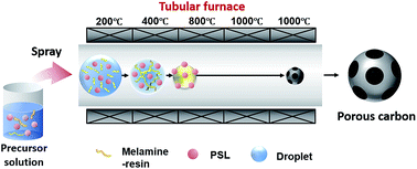
The experimental scheme is shown in Fig. 1. Droplets of the precursor solution were generated using an ultrasonic nebulizer (1.7 MHz, NE-U17, Omron Healthcare Co., Ltd., Kyoto, Japan). Pyrolysis was performed in a horizontal electric tubular furnace consisting of five stacks of the same length. The stack temperatures were set at 200, 400, 800, 1000, and 1000 °C, respectively. Droplets of the precursor solution were carried through the furnace by N2 at a flow rate of 2.2 L min−1. This N2 flow rate was higher than that used in our previous study, to shorten the residence time.15,17 The precursor underwent water evaporation, thermal decomposition, and carbonization in the tubular furnace as the temperature increased. The synthesized particles were collected using an electrostatic precipitator.
image file: c6ra15217a-f1.tif
Fig. 1 Experimental scheme.

The effect of carbonization temperature on the nitrogen content was studied by adjusting the stack temperatures to 200, 400, 800, 800, and 800 °C to represent a carbonization temperature of 800 °C, and 200, 400, 600, 600, and 600 °C to represent a carbonization temperature of 600 °C.

Particles characterization

The droplet size was determined using the laser diffraction technique (Spraytec, Malvern Instrument Ltd., Malvern, UK). The ζ potentials of the melamine resin and PSL template were determined using a zetasizer (Zetasizer Nano ZSP, Malvern Instruments Ltd., Malvern, UK). The thermal behavior of the melamine resin was investigated using thermogravimetric analysis (TGA; TGA-50/51, Shimadzu Corp., Kyoto, Japan) in N2 at a flow rate of 0.7 L min−1. The chemical composition of the synthesized carbon particles was determined using an elemental analyzer (CHNS/0 2400 II, Perkin Elmer Inc., Waltham, MA, USA).

Gas adsorption measurement equipment (BELSORP-max, MicrotracBEL Corp., Osaka, Japan) was used to measure the N2 adsorption–desorption ability of the porous carbon particles, and the surface area was calculated using the Brunauer–Emmett–Teller (BET) method based on the N2 isotherm curve.

A crucible heating approach was used to predict the chemical reactions during thermal decomposition of the melamine resin. Melamine resin samples (about 0.5 g) were heated in a N2 atmosphere in a ceramic furnace at 200, 400, or 1000 °C, with temperature increments of 10 °C min−1. The chemical bonds in each sample were then examined using Fourier-transform infrared (FT-IR) spectroscopy (Spectrum one, Perkin Elmer Inc., Waltham, MA, USA).

The particle morphologies were examined using field-emission scanning electron microscopy (SEM; S-5000, 20 kV, Hitachi High-Tech. Corp., Tokyo, Japan). The pore and particle sizes were determined by measuring more than 300 randomly selected particles. The obtained particle size, Dn, was converted to a volume-average diameter, Dv, using eqn (1).18

 
image file: c6ra15217a-t1.tif(1)
C, M, and ρ denote the droplet concentration, the molecular weight of the droplet, and the particle mass density, respectively.

Results and discussion

Carbonization mechanism

The carbonization mechanism was studied based on the thermal behavior of the melamine resin and FT-IR spectra. The TG curve of the melamine resin (Fig. 2) shows that carbonization involved four stages. In the first stage, up to about 100 °C, the initial weight decreased by 10%. In the second stage, between 150 and about 200 °C, a 20% weight decrease was observed. In the third stage, a significant weight loss occurred at around 400 °C. A further 24% weight loss was observed in the fourth stage (above 400 °C), indicating continuous carbonization.
image file: c6ra15217a-f2.tif
Fig. 2 TG curve of melamine resin in N2 atmosphere.

The reactions occurring during the four-stage carbonization were predicted based on FT-IR spectra at 200, 400, and 1000 °C (Fig. 3). The peak at 1530 cm−1 corresponds to –C[double bond, length as m-dash]N vibrations, and indicates the presence of the melamine triazine ring, the peaks at 1556, 1456, and 1388 cm−1 correspond to methylene C–H vibrations, and the peak at 1060 cm−1 is assigned to ether group vibrations.18 The methylene and ether groups serve as bridges between melamine monomers, therefore the presence of the corresponding vibrations in the spectrum of the raw material implies that the raw material was already an oligomer. The peak at 2930 cm−1 can be attributed to the stretching vibration of the C–H bond in the methylol group and the broad peak at 3330 cm−1 corresponds to the N–H group connected to the triazine ring.19 The spectrum of the sample heated at 200 °C is the same as that of the raw material, indicating that the first-stage weight loss shown in Fig. 2 was purely the result of solvent evaporation. The peak assigned to the N–H group disappeared after heating to 400 °C. A significant decrease in the intensity of the peaks assigned to the triazine ring was also observed, along with cleavage of C–H, ether, and C–N bonds. Scission of the C–N bonds was a continuous process, and started between 100 and 200 °C, because the C–N bond energy is lower than the others. C–N cleavage can lead to the formation of intermediates with amino groups attached to the triazine ring.20 The triazine ring bonds are more stable than C–N bonds, therefore cleavage of the triazine ring occurred between 300 and 400 °C, and contributed to the significant weight loss. Scission of the triazine rings generated a more condensed form of melamine by releasing NH3. Further heating decreased the amounts of aromatic ring and other condensed forms, as shown by the broad peak between 1000 and 2000 cm−1 in the spectrum of the synthesized carbon. This differs significantly from phenol-derived carbon, for which strong aromatic bonds were still present in the synthesized carbon.21 However, a new peak, assigned to CH2 bonds, appeared at 2350 cm−1, which suggests that the synthesized carbon was hydrophobic.


image file: c6ra15217a-f3.tif
Fig. 3 FT-IR spectra of melamine resin before pyrolysis and after pyrolysis at various temperatures.

The changes in the FT-IR spectra and the furnace temperature distribution were used to estimate the positions of the main decomposition reactions inside the furnace, as shown in Fig. 4. The average diameter of the droplets generated by the ultrasonic nebulizer was 5 μm. The time required for the temperature of droplets this size to become the same as the surrounding temperature was estimated to be 1/100 s, according to the correlation reported by Jayanthi et al.22 It is reasonable to assume that the droplet temperature increment was the same as that of the furnace. The furnace was divided into four zones based on reaction type. The furnace length is denoted by z, i.e., z = 0 cm at the furnace inlet. Zone I is located between the furnace inlet and z = 2 cm. This is the zone where water evaporation took place. In zone II, which lies between z = 2 and 14 cm from the inlet, ether bridges and C–N bonds were cleaved and a condensed melamine oligomer was formed. A cured melamine resin was then formed in zone III, which lies between z = 14 and 30 cm. Triazine ring scission continued in zone IV, to form carbon.


image file: c6ra15217a-f4.tif
Fig. 4 Changes in chemical structures during pyrolysis.

The synthesized carbon contained –CH2 and C–N. Because of their higher bonding strengths, the nitrogen atoms that remained after carbonization were those embedded in the aromatic rings, typically pyrrolic, pyridinic, or quaternary nitrogen functional groups. However, the stability of the nitrogen functional groups depended on the carbonization temperature.

Table 1 shows the effect of the carbonization temperature on the nitrogen contents of melamine-derived carbon. The TGA data and summary of the CHN contents show that low carbonization temperatures gave high particle yields and nitrogen contents. The carbon content increased with increasing carbonization temperature. The particle yield at a carbonization temperature of 600 °C was twice that at 1000 °C, and the carbon content of the particles synthesized at 1000 °C was twice that at 600 °C. According to the TG curve provided in Fig. 2, the carbon yield (carbon-to-melamine resin mass ratio) at 1000 °C is 8%. Meanwhile, weight measurement of the collected particles after the spray pyrolysis indicates a yield of approximately 1.15 ± 0.18% for dense carbon and 1.2 ± 0.13 for porous carbon.

Table 1 CHN analysis of carbon particles synthesized at various carbonization temperatures
Carbonization temperature (°C) Composition ratio [%]
C H N Others
600 °C 33.6 2.22 39.2 24.8
800 °C 50.6 1.36 21.7 26.2
1000 °C 67.9 2.27 5.44 24.3


Despite thermal degradation, the nitrogen content of the carbon particles synthesized at 1000 °C was still high compared with those of most carbon particles synthesized via a hydrothermal route and carbonized at 800 °C. In this study, the droplet residence time inside the furnace was approximately 15.7 s, which is significantly lower than the synthesis time required in the liquid-phase route. The short residence time is probably the reason for conservation of the nitrogen content in the spray pyrolysis route.

Effect of melamine resin concentration on particle size

High-resolution (HR) SEM images and the size distributions of the particles synthesized using four melamine resin concentrations are shown in Fig. 5. No PSL template was added to the precursor solution; therefore, the synthesized particles were not porous. These experiments were used to evaluate the quality of the heating process inside the tubular furnace. The dense morphology implies that the heating rate in the tubular furnace was just adequate; there was enough time for the oligomer to diffuse and self-assemble at the droplet centers before the water had completely evaporated. The particles were also completely spherical, indicating that the droplet surfaces experienced a homogeneous heat flux, resulting in a uniform water evaporation rate.
image file: c6ra15217a-f5.tif
Fig. 5 HR-SEM images and particle size distributions of dense carbon particles prepared from 0.25 wt% (a), 0.5 wt% (b), 0.75 wt% (c), and 1.0 wt% (d) melamine resin at a carbonization temperature of 1000 °C.

The average sizes of the particles synthesized using four melamine resin concentrations, i.e., 0.25, 0.5, 0.75, and 1.0 wt%, were 126.8, 135.8, 182.1, and 208.8 nm, respectively. This is reasonable because a higher melamine resin concentration implies more melamine resin per droplet for carbonization. The correlation between the final particle diameter, Dp, and the droplet diameter, Dd, in the case of dense particles synthesized via spray pyrolysis is given by eqn (2).17

 
image file: c6ra15217a-t2.tif(2)
α, C, ρd, and ρc denote the residual ratio, carbon source concentration in the precursor solution, droplet density, and carbon density, respectively. The residual ratio is defined as the mass ratio between the carbon yield and the precursor. Eqn (2) successfully estimated the average particle size, indicated by the coinciding modus of the calculated and measured diameters in Fig. 5. However, the measurement-based particle size distribution was slightly wider than the calculated distribution. This could be caused by droplet agglomeration and segregation arising from collisions inside the tubular furnace, which would result in smaller or larger droplets.

Pore formation and control of porous structure

In the macroporous particle synthesis, the melamine resin and PSL particles were confined in droplets generated by an ultrasonic nebulizer. Because of their homogeneous charge distribution and identical size, the PSL particles inside the droplets can be considered as a symmetric colloidal system. The PSL particles and melamine resin oligomer were positively charged, therefore the presence of counter ions on the PSL particle double-layer boundaries was unlikely; this promoted formation of a thick double layer. The thickness of the double layer was calculated to be approximately 4 nm using the Poisson–Boltzmann equation with the Debye–Hückel approximation (see ESI).23

The lack of counter ions resulted in a low attractive van der Waals force but a high double-layer force between the PSL particles and melamine resin oligomer. Consequently, the Derjaguin–Landau–Vervey–Overbeek profile, which is the sum of the van der Waals and double-layer forces, was dominated by the positive (repulsive) force between the PSL particles and melamine resin oligomer. It is speculated that the final distance between the PSL particles depended on the repulsive colloidal force and the drag force toward the droplet center caused by water evaporation (see Fig. S1 in the ESI). This final distance would determine the final particle structure after carbonization and PSL decomposition, with the melamine resin providing the skeleton of the porous structure.

The effects of PSL concentration on the porous structure were investigated using six PSL concentrations. The SEM images of the resulting particles (Fig. 6) show that the number of pores increased proportionally with increasing PSL concentration. This is reasonable because more PSL particles were confined in one droplet when a higher PSL concentration was used. Another effect of increasing the PSL concentration is the formation of interconnected pores, as observed in the SEM image of the particles synthesized using PSL to melamine resin ratios of 0.8 and higher. The interconnected pores indicate contact between the PSL particle surfaces prior to PSL decomposition, possibly during the water evaporation stage. At this stage, the droplets gradually shrank, causing the PSL particles to move toward the droplet centers. This suggests that the force dragging the PSL toward the droplet centers was stronger than the repulsive force arising from colloidal interactions. Consequently, the surfaces of the PSL particles were in contact with each other, resulting in interconnected pores after PSL decomposition. This indicates that the surface tension of the droplets was sufficient to prevent the PSL particles from leaving the droplets.


image file: c6ra15217a-f6.tif
Fig. 6 HR-SEM images of porous carbon particles prepared using 320 nm-sized PSL with PSL to melamine resin mass ratios of 0.4[thin space (1/6-em)]:[thin space (1/6-em)]1 (a), 0.8[thin space (1/6-em)]:[thin space (1/6-em)]1 (b), 1.2[thin space (1/6-em)]:[thin space (1/6-em)]1 (c), 1.6[thin space (1/6-em)]:[thin space (1/6-em)]1 (d), 2.4[thin space (1/6-em)]:[thin space (1/6-em)]1 (e), and 3.2[thin space (1/6-em)]:[thin space (1/6-em)]1 (f) at a carbonization temperature of 1000 °C.

At a PSL to melamine resin ratio of 3.2[thin space (1/6-em)]:[thin space (1/6-em)]1, the droplets were mostly occupied by PSL particles. The distance between PSL particles decreased and the space available for the melamine resin was limited. There was not enough melamine resin to provide a strong skeletal structure; therefore, the final particles were broken, as shown in Fig. 6(f). A melamine resin to PSL ratio of 1.6[thin space (1/6-em)]:[thin space (1/6-em)]1 is considered to be the most suitable for achieving a strong particle structure.

The particle structure was controlled by changing the ratio of PSL to melamine resin, but the pores size was tuned based on the PSL particle size. Fig. 7 shows HR-SEM images of the porous carbon particles prepared using various PSL particle sizes. The images show that the pores of the resulting particles were smaller than the initial PSL particle size. The ratios between the final pore sizes and the initial PSL particle sizes were 19.6, 25.8, and 23.5% for initial PSL particle sizes of 170, 270, and 370 nm, respectively. This implies that carbonization decreased the particle size of the cured melamine resin as a result of changes in the chemical structure caused by reactions, and particle shrinkage affected the pore size. Although there was no particular trend in pore shrinkage, the particles synthesized using the largest PSL particles tended to have wider pore size distributions. The wide pore size distributions can be attributed to inhomogeneous shrinkage of the skeletal structure. When large PSL particles were used as the template, the skeletal structure that separated one pore from another was relatively thick. Consequently, carbonization of the skeletal structure might not be homogeneous. The parts of the skeleton that were highly carbonized would experience higher shrinkage than the less carbonized parts, resulting in greater pore shrinkage.


image file: c6ra15217a-f7.tif
Fig. 7 HR-SEM images and pores size distribution of porous carbon particles prepared using PSL particles of size 170 nm (a), 270 nm (b), and 370 nm (c) at a PSL to melamine resin mass ratio of 1.6[thin space (1/6-em)]:[thin space (1/6-em)]1 and a carbonization temperature of 1000 °C.

N2 adsorption–desorption isotherm provided in Fig. 8 shows type A hysteresis according to de Boer's classification, indicating cylindrical pores open at both ends and the presence of mesopores.24 The inset of Fig. 8 magnifies the N2 adsorption curve at the beginning of the adsorption process, showing a pointed increase of the adsorbed N2 volume by a small increase of the pressure. However, the volume of adsorbed N2 at this point is insignificant compared to the total N2 adsorbed, which may indicate the presence of a very small amount skeletal micropores. Barrett–Joyner–Halenda analysis of porous carbon prepared using 270 nm PSL with a PSL to melamine resin ratio of 1.6[thin space (1/6-em)]:[thin space (1/6-em)]1 and a carbonization temperature of 800 °C shows dominant macropores and some micro- to mesopores with lower intensities (Fig. SI.2). The specific surface area (SBET) calculated from the N2 adsorption–desorption was 159 m2 g−1.


image file: c6ra15217a-f8.tif
Fig. 8 N2 adsorption–desorption curve of porous carbon particles prepared using 270 nm-sized PSL with a PSL to melamine resin mass ratio of 1.6[thin space (1/6-em)]:[thin space (1/6-em)]1 and a carbonization temperature of 800 °C.

Conclusions

Spray pyrolysis is a promising route for synthesizing nitrogen-functionalized macroporous carbon particles from melamine resin and a PSL particle template. Nitrogen contents of 21.7% and 5.44% were achieved by pyrolysis at 800 and 1000 °C, respectively; these values are significantly higher than those for melamine-derived carbon synthesized via a hydrothermal route at the same carbonization temperature. The short residence time in the spray pyrolysis process is believed to be the key to conserving the nitrogen content. The pore structure and sizes were controlled by changing the ratio of PSL to melamine resin, and the PSL particle size, respectively. The optimum porous structure was obtained using a PSL to melamine resin mass ratio of 1.6[thin space (1/6-em)]:[thin space (1/6-em)]1. These promising preliminary results suggest that it would be worth performing future work on improvement of the carbon yield, to enable mass production, and on performance evaluation for intended applications.

Acknowledgements

This work was supported by a Grant-in-Aid for Young Scientists B (15K182570A), and the Japan Society for the Promotion of Science (JSPS) KAKENHI Grant Numbers 26709061 and 25620164. The authors would like to thank the Japanese Ministry of Education, Culture, Sports, Science, and Technology (MEXT) for providing a doctoral scholarship (A. F. A.).

References

  1. J. Lu, D. Dreisinger and W. Cooper, Hydrometallurgy, 2002, 64, 1–11 CrossRef CAS .
  2. S. Zhang, L. Chen, S. Zhou, D. Zhao and L. Wu, Chem. Mater., 2010, 22, 3433–3440 CrossRef CAS .
  3. L. Zhao, N. Baccile, S. Gross, Y. Zhang, W. Wei, Y. Sun, M. Antonietti and M.-M. Titirici, Carbon, 2010, 48, 3778–3787 CrossRef CAS .
  4. K. Gong, F. Du, Z. Xia, M. Durstock and L. Dai, Science, 2009, 323, 760–764 CrossRef CAS PubMed .
  5. R. Balgis, G. M. Anilkumar, S. Sago, T. Ogi and K. Okuyama, J. Power Sources, 2013, 229, 58–64 CrossRef CAS .
  6. E. Fiset, T. E. Rufford, M. Seredych, T. J. Bandosz and D. Hulicova-Jurcakova, Carbon, 2015, 81, 239–250 CrossRef CAS .
  7. A. F. Arif, Y. Kobayashi, R. Balgis, T. Ogi, H. Iwasaki and K. Okuyama, Carbon, 2016, 107, 11–19 CrossRef CAS .
  8. A. Chen, Y. Yu, Y. Zhang, W. Zang, Y. Yu, Y. Zhang, S. Shen and J. Zhang, Carbon, 2014, 80, 19–27 CrossRef CAS .
  9. J. Yu, M. Guo, F. Muhammad, A. Wang, G. Yu, H. Ma and G. Zhu, Microporous Mesoporous Mater., 2014, 190, 117–127 CrossRef CAS .
  10. Y. a. Huang, F. Yang, Z. Xu and J. Shen, J. Colloid Interface Sci., 2011, 363, 193–198 CrossRef CAS PubMed .
  11. G. Wang, J. Zhang, S. Kuang, J. Zhou, W. Xing and S. Zhuo, Electrochim. Acta, 2015, 153, 273–279 CrossRef CAS .
  12. Y. Zhao, R. Nakamura, K. Kamiya, S. Nakanishi and K. Hashimoto, Nat. Commun., 2013, 4, 2390 Search PubMed .
  13. H. Li, W. Kang, L. Wang, Q. Yue, S. Xu, H. Wang and J. Liu, Carbon, 2013, 54, 249–257 CrossRef CAS .
  14. R. Balgis, A. F. Arif, T. Mori, T. Ogi, K. Okuyama and G. M. Anilkumar, AIChE J., 2015, 62, 440–450 CrossRef .
  15. R. Balgis, T. Ogi, A. F. Arif, G. M. Anilkumar, T. Mori and K. Okuyama, Carbon, 2015, 84, 281–289 CrossRef CAS .
  16. T. Ogi, A. B. D. Nandiyanto and K. Okuyama, Adv. Powder Technol., 2014, 25, 3 CrossRef CAS .
  17. A. F. Arif, R. Balgis, T. Ogi, T. Mori and K. Okuyama, Chem. Eng. J., 2015, 271, 79–86 CrossRef CAS .
  18. W.-N. Wang, A. Purwanto, I. W. Lenggoro, K. Okuyama, H. Chang and H. D. Jang, Ind. Eng. Chem. Res., 2008, 47, 1650–1659 CrossRef CAS .
  19. D. J. Merline, S. Vukusic and A. A. Abdala, Polym. J., 2013, 45, 413–419 CrossRef CAS .
  20. T. Hirata, S. Kawamoto and A. Okuro, J. Appl. Polym. Sci., 1991, 42, 3147–3163 CrossRef CAS .
  21. R. Balgis, T. Ogi, W.-N. Wang, G. M. Anilkumar, S. Sago and K. Okuyama, Langmuir, 2014, 30, 11257–11262 CrossRef CAS PubMed .
  22. G. Jayanthi, S. Zhang and G. L. Messing, Aerosol Sci. Technol., 1993, 19, 478–490 CrossRef CAS .
  23. R. J. Hunter, Zeta potential in colloid science: principles and applications, Academic press, 2013 Search PubMed .
  24. S. Lowell and J. E. Shields, Powder surface area and porosity, Springer Science & Business Media, 2013 Search PubMed .

Footnote

Electronic supplementary information (ESI) available: Comparison of N content in melamine-derived carbon, estimation of double layer thickness and ζ-potential distribution. See DOI: 10.1039/c6ra15217a

This journal is © The Royal Society of Chemistry 2016
Click here to see how this site uses Cookies. View our privacy policy here.