DOI:
10.1039/C6RA15069A
(Paper)
RSC Adv., 2016,
6, 99914-99918
3D graphene–carbon nanotube–nickel ensembles as anodes in sodium-ion batteries†
Received
10th June 2016
, Accepted 10th October 2016
First published on 11th October 2016
Abstract
Sodium ion batteries (SIBs) are fast emerging as an attractive low-cost substitute in applications such as smart grids and large scale energy storage. But traditional carbon anodes used in SIBs face many practical difficulties due to the fact that the sodium ion is 55% larger than its lithium counterpart. Therefore, anodes in SIBs require special architectures to accommodate the large sodium ions without compromising other essential attributes like conductivity and surface area. In this manuscript, we report the synthesis of three dimensional, 3D mesoporous, N-doped graphene–carbon nanotube (G–Ni@NCNT) networks as anodes in SIBs. The graphene–carbon nanotube–nickel ensemble was synthesized by facile catalytic transformation of isocyanate treated graphene oxide under microwave irradiation. When applied as electrodes in sodium-ion batteries, our 3D graphene–carbon nanotube hybrids show a high specific capacitance of 447 mA h g−1, good rate capability and still retain 98.4% of the initial capacitance even after 150 cycles. The carbon nanotubes anchored on the graphene surface act as spacers and increase the electrolyte-accessible surface area whereas the defects generated by substitution doping of nitrogen on graphene and CNT provide good anchoring points for sodium ion retention.
1. Introduction
With the ever increasing popularity of mobile phones, tablets, laptop computers and other personal electronic devices, rechargeable energy storage devices like lithium-ion batteries (LIBs) have become an integral part of our lives. However, lithium is a limited resource and there are concerns that terrestrial sources of lithium may run out in the near future. Though there are efforts to recover lithium metal from spent batteries, the general consensus in the scientific community is to look for “beyond-lithium” based batteries. In light of this, sodium ion batteries (SIBs) have attracted renewed research efforts as an affordable alternative to LIBs for large-scale energy storage applications. Sodium is the 4th most abundant element in the Earth's crust and is widely distributed across all continents when compared to lithium which is concentrated in countries such as Bolivia, Chile, China, Australia and Argentina. Despite these advantages, sodium ion batteries are less in use due to the fact that the storage capacity of typical sodium ion battery is less than half of graphite based LIB. The recent advances in graphene based electrodes in lithium ion batteries have prompted researchers to study the utility of graphene as anodes in SIBs too.1,2 But sodium ion is 55% larger than that of the lithium, consequently a typical graphene based SIB will show 50–60% less capacity than that of graphene based LIB.3 Recent research efforts have shown that carbonaceous materials such as graphene,4 carbon nanotubes5 hard carbons,6 hetero-cycle doped carbon nano assemblies,7 carbons obtained from pyrolysis of biomaterials (bio-chars)8,9 can be used as anode materials in SIBs. Of these, graphene is worth special mention due to its unique combination of chemical and physical properties, excellent conductivity and relatively high surface area. But chemically synthesized graphene from graphite precursor suffers from poor conductivity and low ‘active surface area’ due to its tendency to restack and this re-aggregation of graphene sheets is a major hurdle in realizing its full potential. In order to avoid this, insertion of spacers like metal nano particles,10 polymers,11 carbon nanotubes,12 carbon nano-cups13 etc. have been reported. Of these, nitrogen doped 3D graphene–carbon nanotube structures have attracted considerable attention and synthesis of these functional nano-materials can be broadly categorized into two categories: in situ synthesis from nitrogen containing precursors14 and ex situ substitution doping which involves treating graphene oxide with nitrogenated chemicals.15 But ex situ substitutional doping involves multiple-steps and more importantly, as the name indicates relies on the substitution of nitrogen moieties in the defects on carbon surfaces. Additionally, it is generally known that defects in graphene are more prevalent in edges when compared to bulk. So, in order to overcome these drawbacks, we developed a simple technique to synthesize nitrogen-doped graphene–CNT 3D nano-architectures from 2D isocyanate treated graphene oxide. The isocyanate used in this work is 4,4′-methylene dicyclohexyl diisocyanate, commonly known as H12MDI or PACM and is extensively used in polyurethane foam and adhesive industry as chain extender. The utility of synthesized G–Ni@NCNT as electrode materials in sodium ion battery is also reported.
2. Experimental
2.1 Material and synthesis
Graphene oxide was prepared from high purity expandable graphite (purity of 99%, average size of 200 μm; purchased from Samjung C & G, Korea) using a modified Hummer's method. Reagent grade nickel acetate tetrahydrate and 4,4′-methylene dicyclohexyl diisocyanate were purchased from Aldrich and were used as received. A single step procedure was employed to synthesize carbon nano tubes anchored on graphene 3D nano-structures. Graphene oxide, nickel acetate tetrahydrate and H12MDI were mixed in weight ratios of 1
:
0.25
:
4 and ultrasonicated for 30 minutes. This mixture was transferred to a glass tube, partially sealed with a lid and subjected to microwave irradiation at 700 W for 240 seconds to yield a fluffy powdery solid which was washed with xylene to remove any unreacted H12MDI and subsequently dried in an oven at 100 °C for 60 minutes. [Caution: this microwave reaction releases large amounts of pungent fumes and must be carried out in well ventilated room, preferably in a fume hood. Isocyanates per se are very toxic and proper protective clothing and masks must be worn during this entire process.]
2.2 Characterization and testing
Microwave irradiation was carried out in a domestic microwave oven Model number: KR-B202WL with output power of 700 W and input power of 1120 W operating at 2450 MHz frequency manufactured by Daewoo Korea. Morphology of G–Ni@NCNT was carried using a field-emission scanning electron microscopy (FE-SEM, Nova NanoSEM 230 FEI operating at 10 kV, without any metal coating), high resolution transmission electron microscopy (Talos F200X microscope operating at 200 kV), structural analysis by Raman spectra (LabRAM HR UV/vis/NIR Horiba Jobin-Yvon, France) and chemical analysis by X-ray photoelectron spectroscopy (Sigma Probe Thermo VG spectrometer using Mg Kα X-ray sources). The XPS spectra were curve fitted with a mixed Gaussian–Lorentzian shape using the freeware XPSPEAK version 4.1. Surface area and porosity were measured by nitrogen adsorption and desorption isotherms at 77 K using a BEL Japan Inc. Belsorp Mini II Surface Area and Pore Size Analysis system. Electrochemical tests were conducted using CR2032 coin-type test cells assembled in argon-filled glove box. The composition of working electrodes was 80 wt% active materials (G–Ni@NCNT), 10 wt% ketjen black, and 10 wt% carboxy methyl cellulose binder mixed in absolute ethanol, pasted on Ni foam, and then dried at 100 °C for 12 h in a vacuum before use. Sodium foil was the counter electrode and Celgard 2400 membrane was the separator. The electrolyte was 1 M NaClO4 in 1
:
1 volume of ethylene carbonate (EC) and diethyl carbonate (DEC) with 10 wt% of fluoroethylene carbonate (FEC). The working electrodes were composed of 0.5 g of active material and a sodium foil separated by a micro-porous Celgard 2400 membrane. Galvanostatic charge–discharge cycling tests were performed using an WBCS 3000, Won-A-Tech, Korea battery testing system in the voltage range between 0.001–2.5 V.
3. Results and discussion
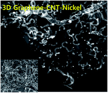
The morphology and microstructure of the product studied by SEM (Fig. 1(a) and (b)) shows extensive growth of carbon nanotubes with typical lengths in the range of several micrometers to several tens of micrometers vertically anchored on graphene substrate. HRTEM micrograph Fig. 1(c) and its corresponding HADF image (Fig. 1(d)) confirm the presence of micrometer long bamboo shaped carbon nanotubes. Additionally, most of the nickel nano particle catalysts are either enclosed in carbon nanotubes or anchored on the surface of the graphene substrate. Careful observation of the bamboo-shape CNTs by HRTEM reveal that nano-tubes are constructed by partitioned short-hollow compartments spaced by curved graphene domes, whereas the outermost graphene sheets are structured continuously along the tube length (Fig. 1(e)) with spheroidal nickel nano-particles embedded inside the carbon nanotubes. The shells are uniform in thickness and usually consist of 7–12 layers with 0.34 nm spacing which is close to that of the graphite (002) planes. The nickel cores are crystalline and have lattice fringe spacing of ∼0.205 nm which is close to that of pristine nickel implying that the nickel catalyst is preferably oriented along (111) direction during CNT growth.16 The nickel nano-particles anchored on graphene substrate exhibits a core–shell structure (Fig. 1(e)) consisting of nickel core embedded within multi-layered graphene shells and the lattice spacing is 0.238 nm indicating the presence of NiOx.17 The mechanism of reduction of graphene oxide and subsequent formation of carbon nanotube can be explained in two concurrent steps. In the first step, the nickel acetate under microwave irradiation thermally decomposes to nickel nano-particles18 which are anchored onto the intrinsic defects on graphene oxide surface caused by localized oxidation and/or mechano-chemical defects generated from sonication during the exfoliation process. Secondly, H12MDI undergoes cyclo-trimerization reaction to form illudine due to the catalytic activity of nickel nano particles anchored on the graphene substrates.19 With further increase in microwave radiation, these illudine moieties are vaporized and are captured by the nickel nano-particles which act as catalytic centres for aromatization process, involving both alkylation and dehydrogenation, leading to the formation of multi-walled carbon nanotubes.
 |
| Fig. 1 SEM (a and b), TEM (c), corresponding dark-field HADF (d), HRTEM image of nickel nano-particles in carbon nano-tubes (e) and HRTEM image of nickel nano-particles anchored on graphene substrate. Insert in (e) and (f) are FFT images. Scale bars are 5 μm in (a) and 500 nm in (b), (c) and (d) and 10 nm in (e) and (f). | |
Raman spectra (Fig. 2(a)) of G–Ni@NCNT shows three peaks associated with nickel with the peak observed around 190 cm−1 attributed to the first order phonon scattering caused by the lattice defects which lowers the symmetry around the atoms. The two peaks at 501 and 506 cm−1 are also manifestations of these defects.20 Besides these nickel peaks, the well known Raman active G band peak of graphene at 1584 cm−1 attributed to the in-plane vibrational mode and 1352 cm−1 peak assigned to the disorder induced by the presence of carbon nanotubes on the graphene substrate are also observed. The ratio of intensities of D band to G band (ID/IG ratio) measured as 0.91 in our G–Ni@NCNT is higher than that of graphene oxide whose ratio is 0.81. The 2D peak occurring in the vicinity of ∼2600 cm−1 is more pronounced and sharper in G–Ni@NCNT when compared to graphene oxide and indicates that the defects on graphene occurring due to oxidization are healed due to the growth of CNT. The chemical composition of G–Ni@NCNT was investigated by X-ray photoelectron spectroscopy (XPS). Fig. 3(b) shows the XPS survey spectra of GO and G–Ni@NCNT samples. In addition to the presence of Ni 2p and N 1s peaks, the survey scan also show that C/O ratio increased from 2.82 observed in GO, to 3.81 in G–Ni@NCNT. This result indicates that there is partial removal of oxygen-containing groups in GO due to microwave induced reduction. XPS spectroscopy is very sensitive and powerful tool to study the composition, structure and oxidation state of nickel moieties. The deconvoluted Ni 2p spectra fitted with a mixed Gaussian–Lorentzian shape using the freeware XPSPEAK version 4.1, is dominated by a single sharp distinct peak at 852.8 eV attributed to zero-valence Ni 2p3/2 and its corresponding satellite peak at 870.4 eV assigned to zero-valence Ni 2p1/2, indicating that bulk of nickel exists in zero-valence state. Additionally, there are minor satellite peaks at 855.4 and 876.2 eV corresponding to Ni2+ 2p3/2 and Ni2+ 2p1/2 respectively.
 |
| Fig. 2 Raman spectra (a) and XPS survey scans (b) of graphene oxide and G–Ni@NCNT; deconvoluted Ni 2p (c) and N 1s (d) XPS spectra of G–Ni@NCNT. | |
 |
| Fig. 3 Cyclic voltammetry studies (a), galvanostatic discharge–charge cycling curves (b), charge–discharge capacity vs. number of cycles (c) and BET surface area pore size distribution of G–Ni@NCNT (d). | |
Another interesting observation is occurrence of a minor peak at 859.9 eV which is attributed to “free NiO”.21 However in our case, lattice calculations from HRTEM image (Fig. 1(f)) indicate presence of NiOx cores embedded in multi-layered graphene shells rather than pure NiO. XPS survey scan of G–Ni@NCNT indicates that there is considerable nitrogen doping corresponding to 8.4 weight% and high resolution deconvoluted N 1s XPS spectra were obtained to elucidate the identity of nitrogen coordination. The deconvoluted N 1s spectra in Fig. 3(d) is dominated by two strong, distinct peaks at 400.8 and 401.7 eV assigned to quaternary nitrogen and protonated amines corresponding to C–N+ moieties. However, it must be mentioned that the 401.7 eV peak is also attributed to the π–π* shake-up satellites in nitrogen doped graphene.22 Besides this a small hump at 398.5 eV is attributed to the pyridinic nitrogen moieties.
Following the pioneering reports by Tarascon group23 on the utility of metal oxide nano-structures as anode materials for lithium ion batteries (LIB), many researchers have investigated the utility of oxides of transition metals like iron, cobalt, nickel and manganese as anodes in sodium-ion batteries too.24,25 However, as observed in LIBs, metal oxide based anodes in SIBs also suffer the same disadvantages like low intrinsic conductivity and huge volume changes during sodiation and desodiation process, resulting in poor cycling stability and lower specific capacity. An effective way of overcoming this drawback is by embedding nickel nano structures in 3D mesoporous conductive graphene–CNT ensembles which offers advantages such as larger interfacial surface area, reduced ion diffusion length between the electrolyte and electrode. Galvanostatic cycling was carried out in the voltage range, 0.001–2.5 V, and at current rate of 100 mA g−1. Fig. 3(a) shows the voltage vs. capacity plots of first three cycles of our three dimensional mesoporous G–Ni@NCNT electrodes. The first cycle exhibits an irreversible reduction peak with a maximum about 0.61 V, caused by irreversible electrochemical formation of SEI layer and reduction of NiO to Ni nano-particles. Additionally, the reductive peak occurring at ∼0.7 V is also attributed to the formation of solid electrolyte inter-phase (SEI) on the surface of carbon grains. In subsequent cycles, the broad hump at 0.91 V corresponds to the reversible process from Ni to NiO and the decomposition of Na2O.26 During oxidation process, the Na-ion insertion–extraction behaviour takes place in two stages with a sharp redox peak at a lower potential region (0–0.2 V) can be clearly observed, which resemble alkali-ion insertion into/extraction out of the graphite structure.27
Additionally, the broad redox peaks detected in the higher potential range of 0.67–1.0 V can be attributed to the charge transfer and Na-ion insertion in the large number of topological defects on the walls of CNT due to N-doping which forms a disordered carbon structure, which further enhances sodium absorption properties.28 Additionally, the large interlayer distance between graphene sheets due to pillaring effect of vertically standing carbon nanotubes also ensures effective transport and storage of Na ions deep in the graphene layers, which additionally contributes to the high rate performance. The redox current peaks tend to stabilize gradually in second and third cycles almost to the point of overlapping, which suggests that after the initial capacity decay occurring in the first cycles our G–Ni@NCNT electrodes shows good Na ion insertion–extraction stability. Fig. 3(b) shows the initial discharge (sodium insertion) and charge (sodium extraction) voltage profiles G–Ni@NCNT anodes at 0.1 Ag−1 exhibiting exceptional initial discharge and charge capacity of 931 and 478 mA h g−1, respectively. The initial columbic efficiency of 51% can be calculated which is primarily due to the irreversible capacity loss occurring in the formation of SEI. The cycling profile during first discharge showed three distinct sloping plateaus: the first occurring in the region at 1.5 to 1.25 V attributed to the Na+ insertion into nickel, the second plateau from 1.25 to 1 V can be attributed to the formation of SEI film on the graphenic domains and the third plateau from 1 to 0.25 V is due to insertion of Na+ in the local disordering caused by nitrogen doping.29,30 In the second discharge curve, the first plateau is almost non-existent and is replaced with a rapidly sloping curve originating at ∼1.25 V due to the domination of Na+ insertion in the graphene and carbon-nanotube structures however a high discharge capacity of 481 mA h g−1 is maintained. This loss in capacity is due to the formation of the SEI film in the first cycle and trapping of Na ions at NiO locations of electrode materials. The morphology of our G–Ni@NCNT mesoporous nanostructures as observed by SEM shows carbon nanotubes anchored on graphene sheet wherein the sodium ions can be adsorbed on the graphene sheet; along the walls of carbon nanotubes, in the interstitial gaps between the nanotubes through the formation of Na2C6. Consequently anodes based on our G–Ni@NCNT shows high discharge capacity of 447 mA h g−1 even after 150 cycles with columbic efficiency of 98.4% is observed (Fig. 3(c)) exhibiting one of the highest sodium ion capacities reported in literature (see Table T1 in ESI†).
This high value of capacity retention with increasing number of cycles can be attributed to meso-porosity observed in SEM and measured by N2-adsorption isotherms (Fig. 3(d)). The existence of out of plane pores on graphene substrate combined with the micro-pores between the nanotube ensembles provide a short ion-transport pathway with minimal resistance and can accommodate the large volume changes of electrode material during sodiation/desodiation process. The N2-adsorption isotherm of the G–Ni@NCNT exhibited a typical combined characteristics of type I/II, with a surface area of 491 m2 g−1 and a total pore volume of 0.51 cm3 g−1. The sharp rise and hysteresis loop in the P/P0 range of ≈0.49–0.89 indicates the presence of micro/nano pores attributed to the ‘spacer’ functionality of nano-tubes which inhibits the restacking of graphene sheets due to van der Waals attraction.
4. Conclusions
In conclusion, we have developed a fast and facile microwave method to synthesize mesoporous, 3D functional nanostructure consisting of nano-meter thin, micrometer long carbon nanotubes vertically anchored on porous graphene substrate from H12MDI, a commodity chemical widely in polyurethane industry. Morphological studies by SEM and TEM showed the developed 3D nano structures are mesoporous with surface area of 491 m2 g−1 tested by nitrogen adsorption/desorption studies. Raman spectra and chemical analysis by XPS indicated that the nitrogen moieties exist as a combination of pyridinic and quaternary nitrogen moieties. When applied as anode in sodium ion batteries, the synthesized nanostructure exhibited high sodium storage capacity of 447 mA h g−1 even after 150 cycles emphasizing the strong synergy between the vertically anchored nitrogen doped carbon nanotubes on graphene substrate.
Acknowledgements
This work was supported by National Research Foundation of Korea (NRF) grant of the Korea government (MSIP) through GCRC-SOP (No. 2011-0030013).
References
- B. L. Ellis and L. F. Nazar, Curr. Opin. Solid State Mater. Sci., 2012, 16, 168 CrossRef CAS.
- R. Raccichini, A. Varzi, S. Passerini and B. Scrosati, Nat. Mater., 2014, 14, 271 CrossRef PubMed.
- S.-W. Kim, D.-H. Seo, X. Ma, G. Ceder and K. Kang, Adv. Energy Mater., 2012, 2, 710 CrossRef CAS.
- X.-F. Luo, C.-H. Yang, Y.-Y. Peng, N.-W. Pu, M.-D. Ger, C.-T. Hsieh and J.-K. Chang, J. Mater. Chem. A, 2015, 3, 10320 CAS.
- Y. Cao, L. Xiao, M. L. Sushko, W. Wang, B. Schwenzer, J. Xiao, Z. Nie, L. V. Saraf, Z. Yang and J. Liu, Nano Lett., 2012, 12, 3783 CrossRef CAS PubMed.
- A. Ponrouch, A. R. Goni and M. R. Palacin, Electrochem. Commun., 2013, 27, 85 CrossRef CAS.
- H. Zhang, X. Zhang, X. Sun, D. Zhang, H. Lin, C. Wang, H. Wang and Y. Ma, ChemSusChem, 2013, 6, 1084 CrossRef CAS PubMed.
- E. M. Lotfabad, J. Ding, K. Cui, A. Kohandehghan, W. P. Kalisvaart, M. Hazelton and D. Mitlin, ACS Nano, 2014, 8, 7115 CrossRef CAS PubMed.
- J. Ding, H. Wang, Z. Li, A. Kohandehghan, K. Cui, Z. Xu, B. Zahiri, X. Tan, E. M. Lotfabad, B. C. Olsen and D. Mitlin, ACS Nano, 2013, 7, 11004 CrossRef CAS PubMed.
- R. Muszynski, B. Seger and P. V. Kamat, J. Phys. Chem. C, 2008, 112, 5263 CAS.
- H. Gomez, M. K. Ram, F. Alvi, P. Villalba, E. Stefanakos and A. Kumar, J. Power Sources, 2011, 196, 4102 CrossRef CAS.
- V. Sridhar, I. Lee, H.-H. Chun and H. Park, RSC Adv., 2015, 5, 68270 RSC.
- V. Sridhar, I. Lee, H. S. Yoon, H. H. Chun and H. Park, Carbon, 2013, 61, 633 CrossRef CAS.
- P. Matter, E. Wang and U. Ozkan, J. Catal., 2006, 243, 395 CrossRef CAS.
- J. Liu, S. Webster and D. L. Carroll, J. Phys. Chem. B, 2005, 109, 15769 CrossRef CAS PubMed.
- D. H. Park, Y. B. Lee, M. Y. Cho, B. H. Kim, S. H. Lee, Y. K. Hong, J. Joo, H. C. Cheong and S. R. Lee, Appl. Phys. Lett., 2007, 90, 093122 CrossRef.
- P. Moravec, J. Smolik, H. Keskinen, J. M. Makela, S. Bakardjieva and V. V. Levdansky, Mater. Sci. Appl., 2011, 264 Search PubMed.
- V. Sridhar, I. Lee, H. H. Chun and H. Park, Carbon, 2015, 87, 186 CrossRef CAS.
- K. P. Loh, Q. Bao, G. Eda and M. Chhowalla, Nat. Chem., 2010, 2, 1015 CrossRef CAS PubMed.
- R. J. Radel, J. M. Sullivan and J. D. Hatfield, Ind. Eng. Chem. Prod. Res. Dev., 1982, 4, 566 CrossRef.
- X. Dong, Y. Ma, G. Zhu, Y. Huang, J. Wang, M. B. Chan-Park, L. Wang, W. Huang and P. Chen, J. Mater. Chem., 2012, 22, 17044 RSC.
- Y. K. Kim and D. H. Min, Langmuir, 2009, 25, 11302 CrossRef CAS PubMed.
- P. Poizot, S. Laruelle, S. Grugeon, L. Dupont and J. M. Tarascon, Nature, 2000, 407, 496 CrossRef CAS PubMed.
- C. D. Wessells, S. V. Peddada, R. A. Huggins and Y. Cui, Nano Lett., 2011, 11, 5421 CrossRef CAS PubMed.
- M. Sawicki and L. L. Shaw, RSC Adv., 2015, 5, 53129 RSC.
- R. Alcantara, M. Jaraba, P. Lavela and J. L. Tirado, Chem. Mater., 2002, 14, 2847 CrossRef CAS.
- S. Wenzel, T. Hara, J. Janek and P. Adelhelm, Energy Environ. Sci., 2011, 4, 3342 CAS.
- H. Shen, D. Rao, X. Xi, Y. Liu and X. Shen, RSC Adv., 2015, 5, 17042 RSC.
- Z. Wang, Y. Li and X.-J. Lv, RSC Adv., 2014, 4, 62673 RSC.
- S. Vadahanambi, H.-H. Chun, K. H. Jung and H. Park, RSC Adv., 2016, 6, 38112 RSC.
Footnote |
† Electronic supplementary information (ESI) available. See DOI: 10.1039/c6ra15069a |
|
This journal is © The Royal Society of Chemistry 2016 |
Click here to see how this site uses Cookies. View our privacy policy here.